ORDER NO.
PIONEER CORPORATION 4-1, Meguro 1-chome, Meguro-ku, Tokyo 153-8654, Japan
PIONEER ELECTRONICS SERVICE, INC. P.O. Box 1760, Long Beach, CA 90801-1760, U.S.A.
PIONEER EUROPE NV Haven 1087, Keetberglaan 1, 9120 Melsele, Belgium
PIONEER ELECTRONICS ASIACENTRE PTE. LTD. 253 Alexandra Road, #04-01, Singapore 159936
PIONEER CORPORATION 2000
PRO-710HD
PROJECTION MONITOR RECEIVER
ARP3086
TZZK DEC. 2000 Printed in Japan
PRO-610HD
PRO-510HD
SD-582HD5
SD-532HD5
THIS MANUAL IS APPLICABLE TO THE FOLLOWING MODEL(S) AND TYPE(S).
Type
Model
Power Requirement
Remarks
PRO-710HDPRO-610HDPRO-510HD SD-582HD5 SD-532HD5
KUXC/CA
AC120V
KBXC
AC120V
In PRO-710HD, PRO-610HD, PRO-510HD, SD-582HD5 and SD-532HD5, there are two
different models (original model and value analysis model) respectively. Confirm the
serial No. of the product rear side, and use each service manual.
Refer to page 2.
1. SAFETY INFORMATION ....................................... 3
2. EXPLODED VIEWS AND PARTS LIST ................. 5
3. BLOCK DIAGRAM AND SCHEMATIC DIAGRAM ... 22
4. PCB CONNECTION DIAGRAM ........................... 87
CONTENTS
5. PCB PARTS LIST .............................................. 108
6. ADJUSTMENT ................................................... 120
7.1.3 WIRING DIAGRAM ....................................... 122
PRO-710HD, PRO-610HD, PRO-510HD,
SD-582HD5, SD-532HD5
2
SERIAL NO.
Serial No.
Model No.
Service Manual
1
PRO-710HD, PRO-610HD, PRO-510HD,
ARP3086 [This manual]
SD-582HD5, SD-532HD5
(value analysis model)
ARP3047, ARP3051 (PRO-610HD)
PRO-610HD, PRO-510HD,
ARP3047, ARP3051 (PRO-610HD)
OTHER
SD-582HD5, SD-532HD5
(original model)
PRO-710HD
(original model)
ARP3065 (PRO-710HD)
ARP3047, ARP3051 (PRO-610HD)
Part No.
original model
value analysis model
Mark
Symbol and Description
PRO-710HD SD-582HD5 PRO-710HD SD-582HD5
Remarks
PRO-610HD SD-532HD5 PRO-610HD SD-532HD5
PRO-510HD
PRO-510HD
POWER SUPPLY ASSY
AWV1795
AWV1808
AWV1872
AWV1869
*1
AWV1873
KBXC Type only
DEFLECTION SERVICE ASSY
AWV1809
AWV1809
AWV1809
AWV1809
AMP ASSY
AWV1797
AWV1797
AWV1797
AWV1797
*2
NSP
DIGITAL CONV. ASSY
AWV1798
AWV1803
AWV1798
AWV1803
Refer to ARP3047
VIDEO ASSY
AWV1799
AWV1804
AWV1799
AWV1804
Refer to ARP3047
SIGNAL ASSY
AWV1800
AWV1805
AWV1866
AWV1870
*1
SUB VIDEO SERVICE ASSY
AWV1819
Not used
AWV1868
Not used
*1
SUB VIDEO ASSY
Not used
AWV1806
Not used
AWV1871
*1
AV I/O ASSY
AWV1802
AWV1807
AWV1802
AWV1807
Refer to ARP3047
CONTRAST OF PCB ASSEMBLIES
*1 : There is not interchangeability with original model and value analysis model.
*2 : By design change, the IC5101, IC5151 and IC5201 of AMP ASSY was changed in TDA6120QN2 by TDA6120QN1.
And diodes is necessary in case of TDA6120QN2. Refer to "3.36 R, G and B CRT ASSY" schematic diagram.
3
PRO-710HD, PRO-610HD, PRO-510HD,
SD-582HD5, SD-532HD5
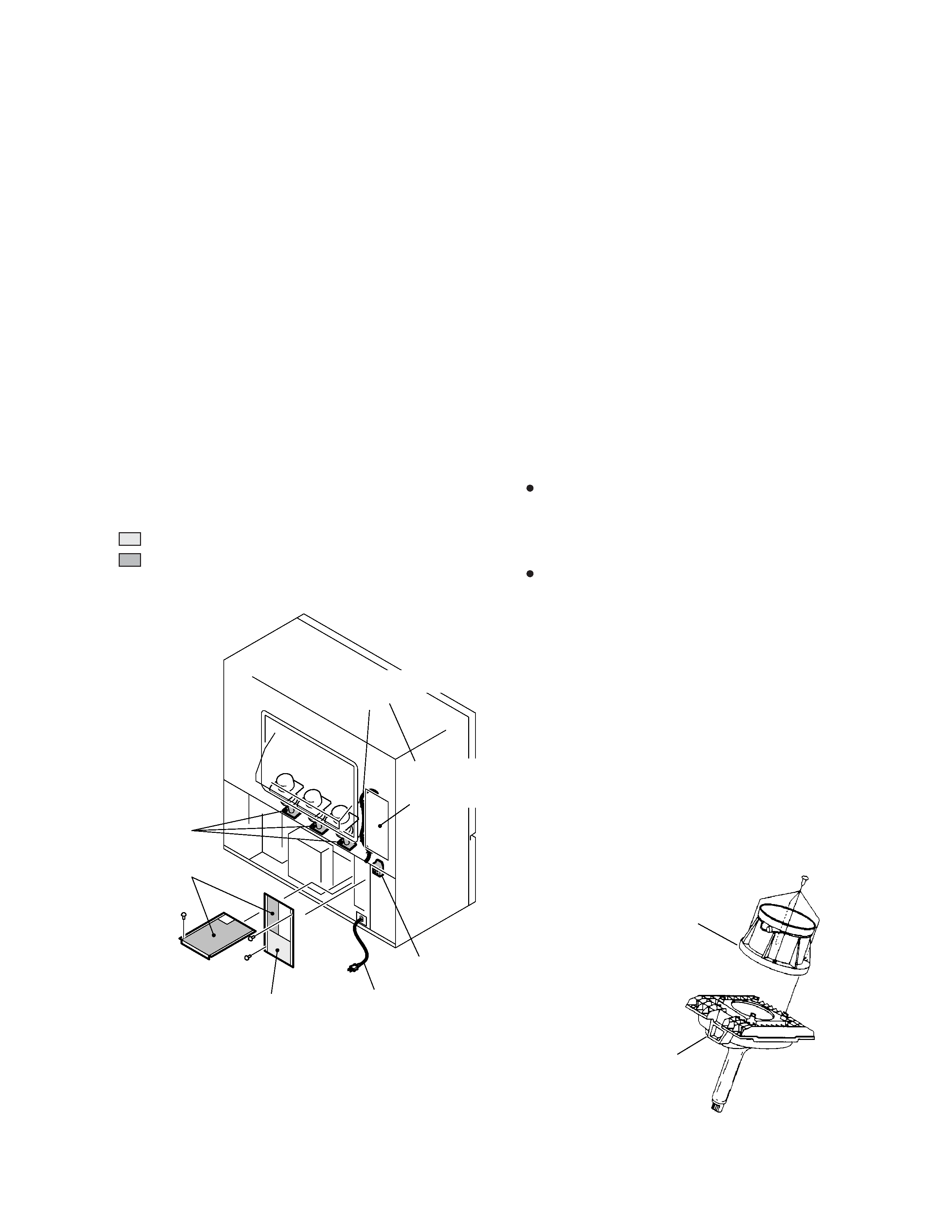
1.3 CHARGED SECTION, HIGH VOLTAGE GENERATING POINT
AND X-RAY PROTECTION
7 Charged section
The circuit in which the commercial AC power is used as it
is without passing through the power supply transformer. If
the charged section is touched, there is a risk of electric
shock. In addition, the measuring equipment can be dam-
aged if it is connected to the GND of the charged section
and the GND of the non-charged section while connecting
the set directly to the commercial AC power supply. In this
case, be sure to connect the set via an insulated transformer
and supply the current.
7 Charged section
(Power supply primary side)
1. The primary side of the AC IN assy
2. AC power cord
3. The primary side of the POWER SUPPLY assy
4. AC power cord for DTV STB
(PRO-710HD, PRO-610HD and PRO-510HD Only)
7 X-ray protection
Regarding the parts which are relative to radiation of X-
rays (There is the danger to radiate X-ray from the indi-
vidual CRT assy R, G, B), there are notifications of cau-
tion in the individual schematic diagrams. Be sure to read
them for safety's sake.
The component parts for X-ray protection are as follows :
When the current flows to the CRT assy R, G, B, be sure
to perform it with these parts being attached. Protection
from the X-ray radiation is maintained in the state in which
these parts have been installed to the CRT assy. R, G, B.
Accordingly, never supply current only to the CRT assy R,
G, B.
Moreover, the anode voltage of the CRT assy R, G, B
should always be kept not higher than the predetermined
value (in the minimum brightness and picture state when
non signal input is less than 30.5kV). Be sure to drive the
CRT assy R, G, B by using a completely functional DE-
FLECTION assy which have been adjusted completely in
the combined state. (When the voltage abnormally be-
comes high, the X-ray protection circuit will operate.)
1. CRT assy R, G, B (Do not dismantle CRT assemblies
under any circumastances)
2. Each Lens assy
Fig. 2 Component parts for X-ray protection
High Voltage
generating point
High Voltage
generating point
High Voltage
generating point
AC Power cord
Charged section
AC power cord for
DTV STB
PRO-710HD,
PRO-610HD,
PRO-510HD
Only
7 High voltage generating point
The place where voltage is 100V is generated.
1.Charged seciton
DEFLECTION assy
(including FBT)
(30.5kV, 1.2kV, 210V,135V)
2. POWER SUPPLY assy
(135V)
3. R. CRT DRIVE assy
(10.5kV, 210V)
4. G. CRT DRIVE assy
(10.5kV, 210V)
5. B. CRT DRIVE assy
(10.5kV, 210V)
6. CRT assy R (CRT service assy R) (30.5kV)
7. CRT assy G (CRT service assy G) (30.5kV)
8. CRT assy B (CRT service assy B) (30.5kV)
9. Focus variable resistor(VR1)
(10.5kV)
10. Deflection yokes (L1, L2 and L3) Approx. (1100V at peak)
Fig. 1 Charged section and high voltage generating point
CRT Assy R, G, B
Each Lens Assy
: Part is the charged section.
: Part is the high voltage generating
points other than the charged section.
1. SAFETY INFORMATION

4
PRO-710HD, PRO-610HD, PRO-510HD,
SD-582HD5, SD-532HD5
5
PRO-710HD, PRO-610HD, PRO-510HD,
SD-582HD5, SD-532HD5
2. EXPLODED VIEWS AND PARTS LIST
NOTES :
Parts marked by " NSP " are generally unavailable because they are not in our Master Spare Parts List.
The
mark found on some component parts indicates the importance of the safety factor of the part.
Therefore, when replacing, be sure to use parts of identical designation.
÷ Parts marked by
are important parts which relate in X-rays radiation.
If any of these parts need to be replaced, always replace with specified parts.
Screws adjacent to
mark on the product are used for disassembly.
2.1 PACKING
Remove
Attach
24
18
20
22
PRO-710HD,
PRO-610HD Only
PRO-710HD,
PRO-610HD
Only
22
29
31
31
30
32
27
Side View
Side View
Screen Frame
PRO-710HD, PRO-610HD,
PRO-510HD Only
PRO-710HD Only
23
22
(
×12: PRO-710HD)
(
×12: PRO-610HD)
(
×8 : PRO-510HD)
19
1
7
8
10
2
9
4
25 to 28, 32
3
35
36
37
11
12
13
15
16
14
17
29 to 31
5
6
33
34
Accessory
(PRO-710HD, PRO-610HD, PRO-510HD Only)