ORDER NO.
PIONEER CORPORATION 4-1, Meguro 1-chome, Meguro-ku, Tokyo 153-8654, Japan
PIONEER ELECTRONICS (USA) INC. P.O. Box 1760, Long Beach, CA 90801-1760, U.S.A.
PIONEER EUROPE NV Haven 1087, Keetberglaan 1, 9120 Melsele, Belgium
PIONEER ELECTRONICS ASIACENTRE PTE. LTD. 253 Alexandra Road, #04-01, Singapore 159936
PIONEER CORPORATION 2001
ARP3095
T ZZY SEPT. 2001 Printed in Japan
PRO-720HD
PROJECTION MONITOR RECEIVER
PRO-620HD
PRO-520HD
1. SAFETY INFORMATION ....................................... 2
2. EXPLODED VIEWS AND PARTS LIST ................. 6
3. BLOCK DIAGRAM AND SCHEMATIC DIAGRAM ... 22
4. PCB CONNECTION DIAGRAM ......................... 112
5. PCB PARTS LIST .............................................. 168
CONTENTS
This service manual should be used together with the following manual(s):
Model No.
Order No.
Remarks
PRO-720HD
ADJUSTMENT, GENERAL INFORMATION,
PRO-620HD
ARP3099
PANEL FACILITIES AND SPECIFICATIONS
PRO-520HD
THIS MANUAL IS APPLICABLE TO THE FOLLOWING MODEL(S) AND TYPE(S).
Power Requirement
Type
Model
PRO-720HD PRO-620HD PRO-520HD
Remarks
KUXC/CA
AC120V

2
PRO-720HD, PRO-620HD, PRO-520HD
1. SAFETY INFORMATION
This service manual is intended for qualified service technicians ; it is not meant for the casual do-it-
yourselfer. Qualified technicians have the necessary test equipment and tools, and have been trained
to properly and safely repair complex products such as those covered by this manual.
Improperly performed repairs can adversely affect the safety and reliability of the product and may
void the warranty. If you are not qualified to perform the repair of this product properly and safely, you
should not risk trying to do so and refer the repair to a qualified service technician.
WARNING
This product contains lead in solder and certain electrical parts contain chemicals which are known to the state of California to cause
cancer, birth defects or other reproductive harm.
Health & Safety Code Section 25249.6 Proposition 65
NOTICE
(FOR CANADIAN MODEL ONLY)
Fuse symbols
(fast operating fuse) and/or
(slow operating fuse) on PCB indicate that replacement parts must
be of identical designation.
REMARQUE
(POUR MODÈLE CANADIEN SEULEMENT)
Les symboles de fusible
(fusible de type rapide) et/ou
(fusible de type lent) sur CCI indiquent que les pièces
de remplacement doivent avoir la même désignation.
1.1 SAFETY PRECAUTIONS
NOTICE : Comply with all cautions and safety related notes
located on or inside the cabinet and on the chassis or
picture tube.
The following precautions should be observed :
1. Do not install, remove, or handle the picture tube in any manner
unless shatterproof goggles are worn.
People not so equipped should be kept away while picture tubes
are handled.
Keep picture tube away from the while handling.
2. When service is required, even though the HDTV PROJECTION
MONITOR an isolation transformer should be inserted between
power line and the set in safety before any service is performed.
3. When replacing a chassis in the set, all the protective devices
must be put back in place, such as barriers, nonmetallic knobs,
adjustment and compartment covershields, isolation resistor-
capacitor, etc.
4. When service is required, observe the original lead dress. Extra
precaution should be taken to assure correct lead dress in the
high voltage circuitry area.
5. Always use the manufacture's replacement components.
Especially critical components as indicated on the circuit
diagram should not be replaced by other manufacture's.
Furthermore where a short circuit has occurred, replace those
components that indicate evidence of overheating.
6. Before returning a serviced set to the customer, the service
technician must thoroughly test the unit to be certain that it is
completely safe to operate without danger of electrical shock,
and be sure that no protective device built into the set by the
manufacture has become defective, or inadvertently defeated
during servicing.
Therefore, the following checks should be performed for the
continued protection of the customer and service technician.
Leakage Current Cold Check
With the AC plug removed from the 120V AC 60Hz source, place
a jumper across the two plug prongs. Turn the AC power switch
on. Using an insulation tester (DC 500V), connect one lead to the
jumpered AC plug and touch the other lead to each exposed metal
part (input/output terminals, screwheads, metal overlays, control
shafts, etc.), particularly any exposed metal part having a return
path to the chassis should have a minimum resistor reading of
0.3M
and a maximum resistor reading of 5M. Any resistor value
below or above this range indicates an abnormality which requires
corrective action. Exposed metal parts not having a return path to
the chassis will indicate an open circuit.
3
PRO-720HD, PRO-620HD, PRO-520HD
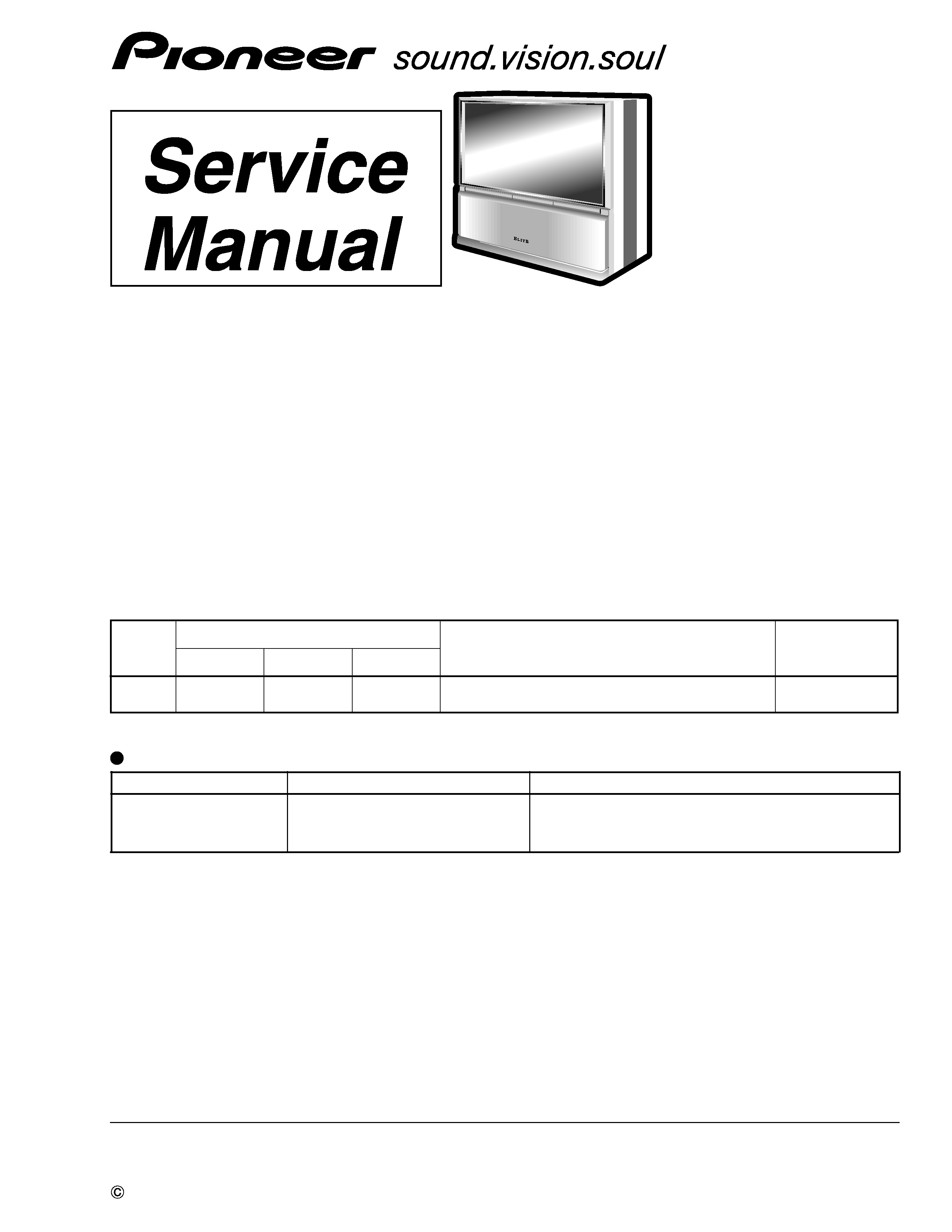
Leakage Current Hot Check
Plug the AC line cord directly into a 120V AC 60Hz outlet (do not
use an isolation transformer for this check). Turn the AC power
switch on.
Using a "Leakage Current Tester (Simpson Model 229 equivalent)",
measure for current from all exposed metal parts of the cabinet (input/
output terminals, screwheads, metal overlays, control shaft, etc.),
particularly any exposed metal part having a return path to the
chassis, to a known earth ground (water pipe, conduit, etc.). Any
current measured must not exceed 0.5mA.
ANY MEASUREMENTS NOT WITHIN THE LIMITS
OUTLINED ABOVE ARE INDICATIVE OF A POTENTIAL
SHOCK HAZARD AND MUST BE CORRECTED BEFORE
RETURNING THE SET TO THE CUSTOMER.
High Voltage
This set is provided with a X-ray protection for clearly indicating
that voltage has increased in excess of a predetermined value.
Comply with all notes described in this Service Manual regarding
this hold down circuit when servicing, so that this X-ray protection
may correctly be operated.
Serviceman Warning
In the status of the black picture (video muting is being applied)
when no signal is input, high voltage of this set during operation is
less than 30.5kV. In case any component having some relation to
the high voltage is replaced, confirm that the high voltage is lower
than 30.5kV in the status of the black picture when no signal is
input.
To measure H. V. use a high impedance H. V. meter.
Connect () to earth and (+) to the FBT anode cable connector. (Refer
to section "7.1.2 DISASSEMBLY".)
X-radiation
TUBE : The primary source of X-radiation in this set is the picture
tube.
For continued X-radiation protection, the replacement tube must be
the same type as the original, PIONEER approved type.
The picture tube (CRT Service Assy R, G, B) used in this set holds
complete guarantee against X-ray radiation when the X-ray is sealed
(See page 4). Accordingly, when the current in flowing to the picture
tube (CRT Service Assy R, G, B), be sure to perform it by putting
the tube into X-ray sealed applied state. Avoid absolutely to flow
the current to the picture tube (CRT Service Assy R, G, B) itself.
Moreover, when the voltage of the high voltage circuit becomes
abnormally a little higher, the picture tube radiates X-rays.
Accordingly, when servicing the high voltage circuit be sure to
replace as an assy with the POWER SUPPLY Assy in the manner
in which has been adjusted to perform normal operation.
1.2 PRODUCT SAFETY NOTICE
Many electrical and mechanical parts in PIONEER set have special
safety related characteristics. These are often not evident from visual
inspection nor the protection afforded by them necessarily can be
obtained by using replacement components rated for higher voltage,
wattage, etc. Replacement parts which have these special safety
characteristics are identified in this Service Manual.
Electrical components having such features are identified by marking
with a
on the schematics and on the parts list in this Service
Manual.
The use of a substitute replacement component which dose not have
the same safety characteristics as the PIONEER recommended
replacement one, shown in the parts list in this Service Manual,
may create shock, fire, X-radiation, or other hazards.
Product Safety is continuously under review and new instructions
are issued from time to time. For the latest information, always
consult the current PIONEER Service Manual. A subscription to,
or additional copies of, PIONEER Service Manual may be obtained
at a nominal charge from PIONEER.
Leakage
current
tester
Reading should
not be above
0.5mA
Device
under
test
Test all
exposed metal
surfaces
Also test with
plug reversed
(Using AC adapter
plug as required)
Earth
ground
AC Leakage Test
4
PRO-720HD, PRO-620HD, PRO-520HD
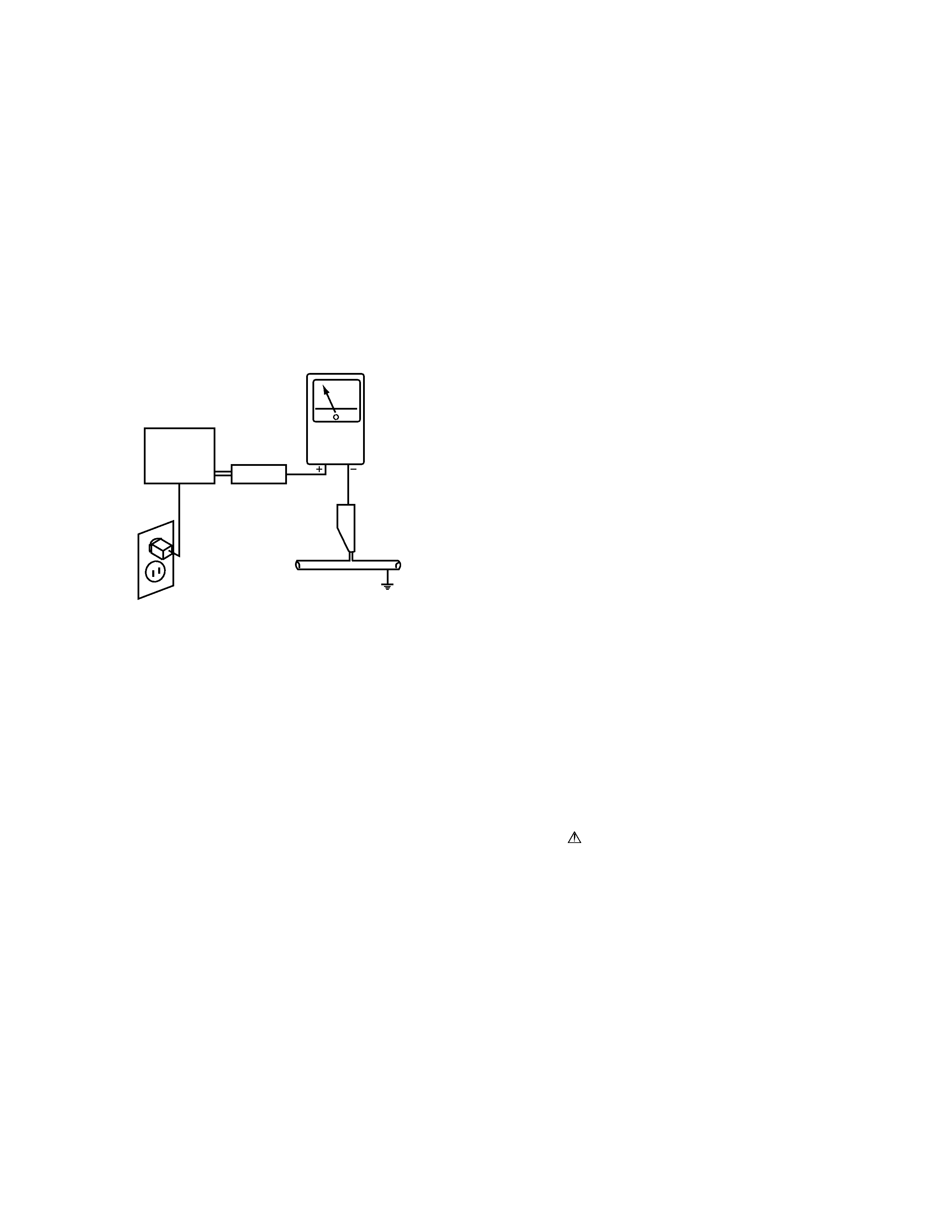
1.3 CHARGED SECTION, HIGH VOLTAGE GENERATING POINT AND X-RAY
PROTECTION
7 Charged section
The circuit in which the commercial AC power is used as it
is without passing through the power supply transformer. If
the charged section is touched, there is a risk of electric
shock. In addition, the measuring equipment can be dam-
aged if it is connected to the GND of the charged section
and the GND of the non-charged section while connecting
the set directly to the commercial AC power supply. In this
case, be sure to connect the set via an insulated transformer
and supply the current.
7 Charged section
(Power supply primary side)
1. The primary side of the AC IN assy
2. AC power cord
3. The primary side of the POWER SUPPLY assy
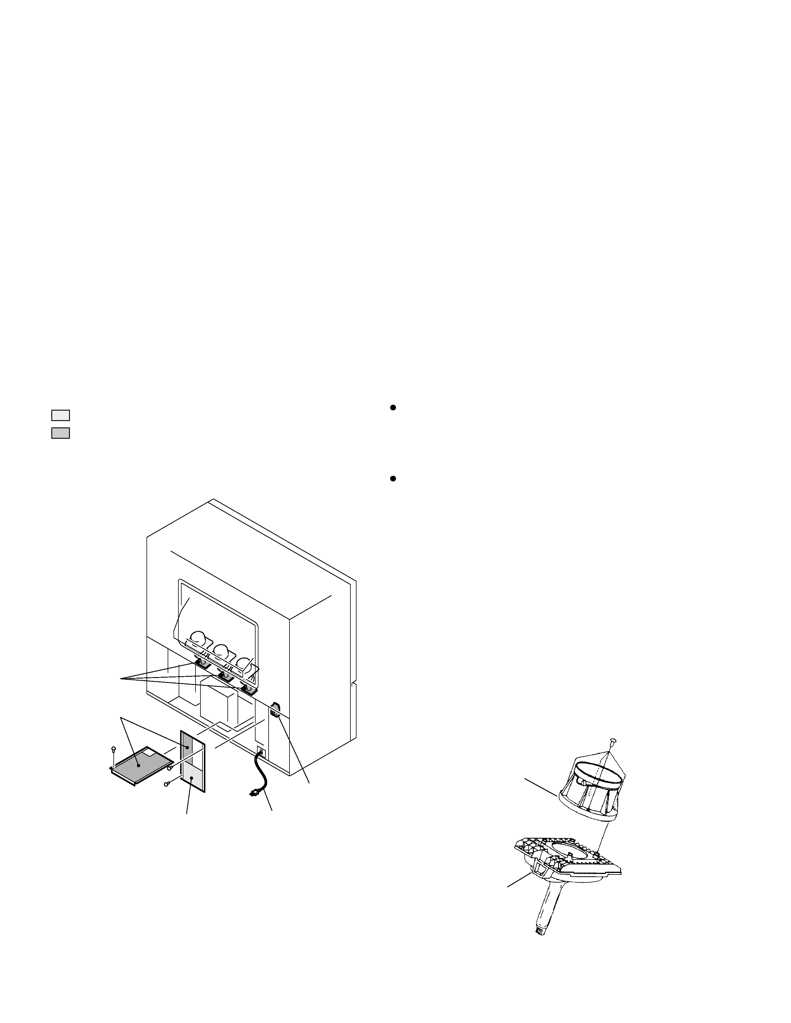
Fig. 2 Component parts for X-ray protection
7 High voltage generating point
The place where voltage is 100V is generated.
1.Charged seciton
DEFLECTION assy
(including FBT)
(30.5kV, 1.2kV, 210V,135V)
2. POWER SUPPLY assy
(135V)
3. R. CRT DRIVE assy
(10.5kV, 210V)
4. G. CRT DRIVE assy
(10.5kV, 210V)
5. B. CRT DRIVE assy
(10.5kV, 210V)
6. CRT assy R (CRT service assy R) (30.5kV)
7. CRT assy G (CRT service assy G) (30.5kV)
8. CRT assy B (CRT service assy B) (30.5kV)
9. Focus variable resistor(VR1)
(10.5kV)
10. Deflection yokes (L1, L2 and L3) Approx. (1100V at peak)
Fig. 1 Charged section and high voltage generating point
: Part is the charged section.
: Part is the high voltage generating
points other than the charged section.
High Voltage
generating point
High Voltage
generating point
High Voltage
generating point
AC Power cord
Charged section
CRT Assy R, G, B
Each Lens Assy
7 X-ray protection
Regarding the parts which are relative to radiation of X-
rays (There is the danger to radiate X-ray from the indi-
vidual CRT assy R, G, B), there are notifications of cau-
tion in the individual schematic diagrams. Be sure to read
them for safety's sake.
The component parts for X-ray protection are as follows :
When the current flows to the CRT assy R, G, B, be sure
to perform it with these parts being attached. Protection
from the X-ray radiation is maintained in the state in which
these parts have been installed to the CRT assy. R, G, B.
Accordingly, never supply current only to the CRT assy R,
G, B.
Moreover, the anode voltage of the CRT assy R, G, B
should always be kept not higher than the predetermined
value (in the minimum brightness and picture state when
non signal input is less than 30.5kV). Be sure to drive the
CRT assy R, G, B by using a completely functional DE-
FLECTION assy which have been adjusted completely in
the combined state. (When the voltage abnormally be-
comes high, the X-ray protection circuit will operate.)
1. CRT assy R, G, B (Do not dismantle CRT assemblies
under any circumastances)
2. Each Lens assy

5
PRO-720HD, PRO-620HD, PRO-520HD