ORDER NO.
PIONEER CORPORATION 4-1, Meguro 1-Chome, Meguro-ku, Tokyo 153-8654, Japan
PIONEER ELECTRONICS SERVICE, INC. P.O. Box 1760, Long Beach, CA 90801-1760, U.S.A.
PIONEER ELECTRONIC (EUROPE) N.V. Haven 1087, Keetberglaan 1, 9120 Melsele, Belgium
PIONEER ELECTRONICS ASIACENTRE PTE. LTD. 253 Alexandra Road, #04-01, Singapore 159936
PIONEER CORPORATION 1999
PRO-610HD
PROJECTION MONITOR RECEIVER
ARP3051
OZZR NOV. 1999 Printed in Japan
CONTENTS
PRO-510HD
KUXC/CA
AC120V
KBXC
AC120V
THIS MANUAL IS APPLICABLE TO THE FOLLOWING MODEL(S) AND TYPE(S).
Type
Power Requirement
Model
Remarks
SD-582HD5
SD-532HD5
PRO-610HD PRO-510HD SD-582HD5 SD-532HD5
This service manual should be used together with the following manual(s):
Remarks
Order No.
PRO-610HD
ARP3047
Model No.
6. ADJUSTMENT ................................................ 195
7. GENERAL INFORMATION ............................ 219
7.1 DIAGNOSIS .............................................. 219
7.1.1 DIAGNOSIS METHOD .................... 219
7.1.2 DISASSEMBLY ............................... 224
7.1.3 WIRING DIAGRAM ......................... 226
7.2 IC .............................................................. 228
7.3 EXPLANATION ......................................... 254
8. PANEL FACILITIES AND SPECIFICATIONS
.............................................................. 266

194
PRO-610HD, PRO-510HD, SD-582HD5, SD-532HD5
195
PRO-610HD, PRO-510HD, SD-582HD5, SD-532HD5
6.1 INTRODUCTION
· IMPORTANT
When replacement of the following assemblies are required during repairs, be sure to replace the EEPROMs with the mounted ones in order to
retain the adjustment data of the unit and to facilitate adjustment after the replacement of the assemblies.
Notes:
· Even if the EEPROMs are replaced, adjustment may be necessary, depending on the part or assembly to be replaced.
For details, see page 197.
· Even if the EEPROMs are replaced, if the EEPROMs are damaged or if their data have been changed from the adjustment data, the status
before the failure will not be restored. Check the status of the unit after replacement of the EEPROMs, and readjust if necessary.
6. ADJUSTMENT
Name of Assy
EEPROM
Main Contents of Memory
SIGNAL Assy
IC2454 [24LC32(I)P]
Adjustment data, such as W/B and color data, in FACTORY mode
User data set on the MENU
DIGITAL CONV. Assy
IC1410 [24LC128P]
Convergence adjustment data
IC1656 [24LC08B(I)P]
Convergence offset data
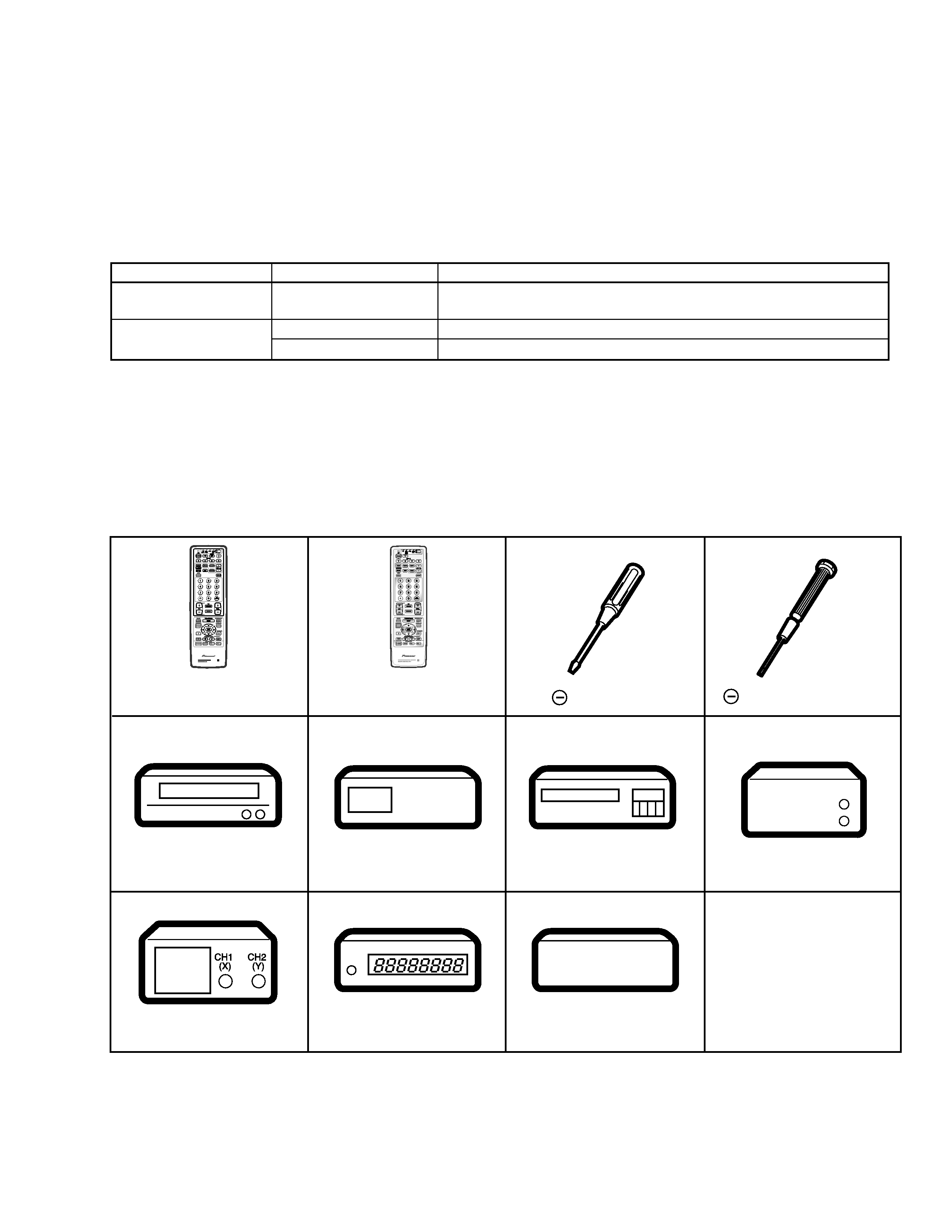
Remote control unit
AXD1448 (CU-SD110)
(For PRO-610HD, PRO-510HD)
Remote control unit
AXD1449 (CU-SD111)
(For SD-582HD5, SD-532HD5)
Monoscope
For HD Signal generator
Screwdriver
Adjustment screwdriver
Dual-trace oscilloscope
Frequency counter
Color bar generator
D. DC Voltmeter
LD Player
6.2 JIGS AND MEASURING INSTRUMENTS
196
PRO-610HD, PRO-510HD, SD-582HD5, SD-532HD5
6.3 ADJUSTMENT LOCATION AND ITEMS
Assembly Adjustment Location
DEFLECTION (SERVICE) ASSY
Adjustment Items
A
CONV. AMP ASSY
B
DIGITAL CONV. ASSY
Front View
C
Focus VR (VR1)
Focus VR
B
G
R
CRT assy B
Deflection
Yoke (B)
Deflection
Yoke
TP-BK
TP-GK
B CRT DRIVE
assy
Centering magnet
(Turn in either direction untill cross signal becomes white.)
G CRT DRIVE
assy
R CRT DRIVE
assy
Deflection
Yoke (G)
Deflection
Yoke (R)
CRT assy R
CRT assy G
1
Brightness Adjustment
2
Deflection Yoke Adjustment
3
Focus Adjustment
4
Test-cross Position Check
5
Screen Size Adjustment
6
Convergence Adjustment
7
White Balance Adjustment
8
Panel Adjustment
9
Panel Adjustment for DTV
Lens assy
(For Red)
Lens assy
(For Blue)
Lens assy
(For Green)
SUB VIDEO ASSY
E
SIGNAL ASSY
F
VIDEO ASSY
D
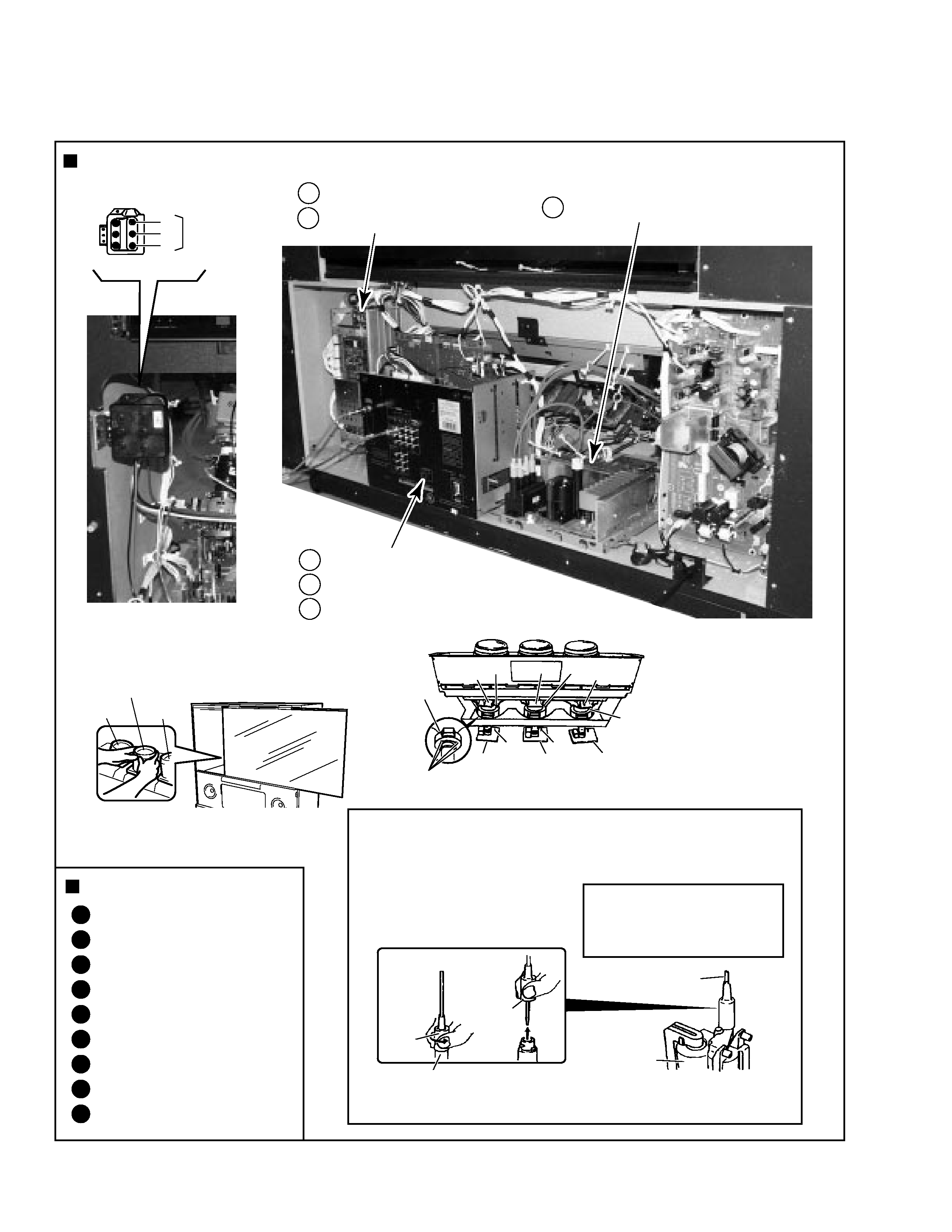
Rear View
Rubber
Cover
Holding the rubber cover firmly,
turn counterclockwise and
check that the lock has
been disengaged.
FBT
Pull straight up
Anode Cable
MEASURING METHOD
SERVICEMAN WARNING
Note :
When reconnecting the cable, proceed in the
reverse order. After reconnecting, tug on the
cable to check that it is secure.
Before removing the anode cable, turn
off the power, unplug the AC plug and
let the unit discharge for more than 1
minut.
Disconnect the FBT anode cable as shown below.
Measure at the point where the cable enters the FBT.
Caution : Take extra precaution when
measuring the voltage. High voltage are also
present in surrounding circuit boards. (CRT
assy, POWER SUPPLY assy)
197
PRO-610HD, PRO-510HD, SD-582HD5, SD-532HD5
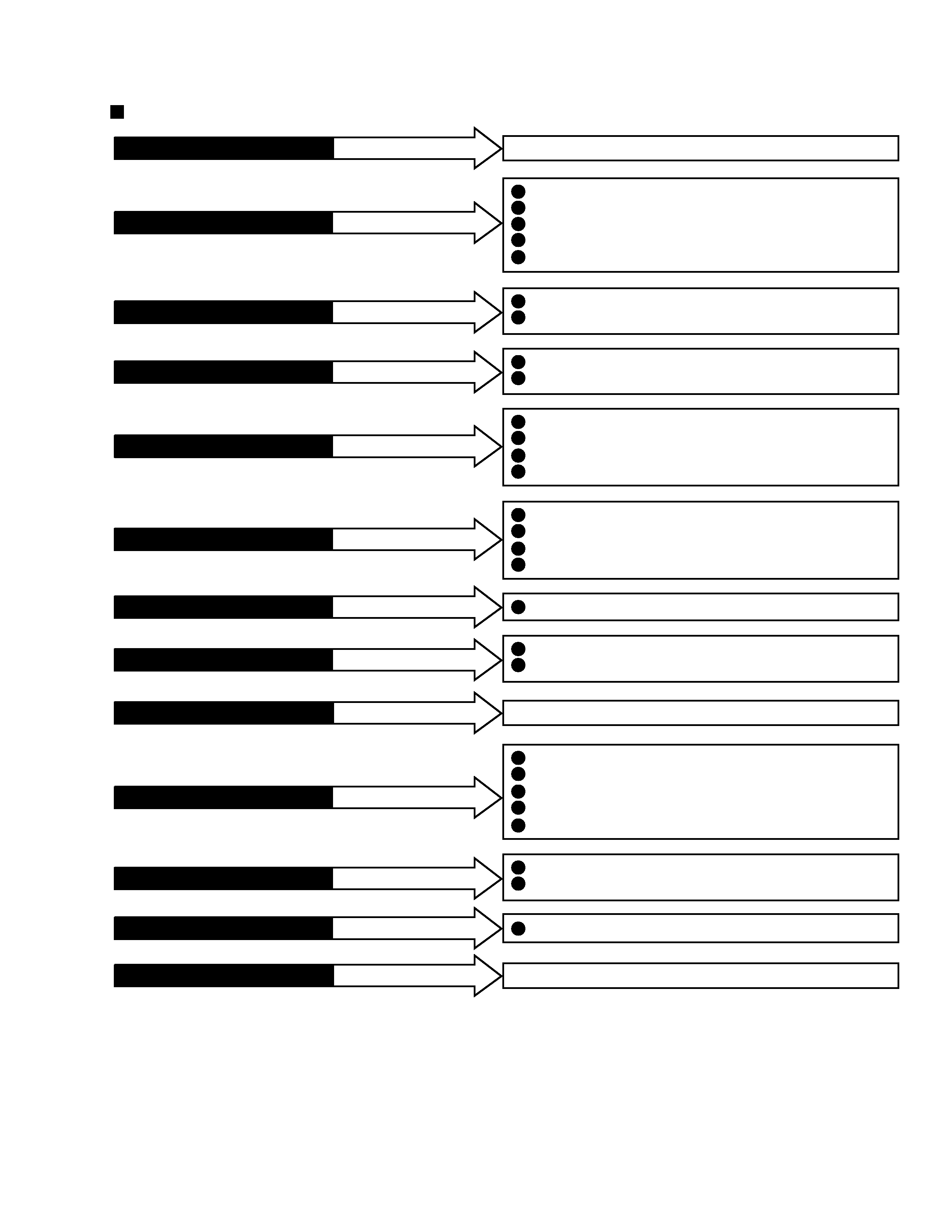
If POWER SUPPLY ASSY
Brightness Adjustment (
2)
Focus Adjustment (VR1: FOCUS VR) (
2)
Screen Size Adjustment (
2)
Convergence Adjustment (
2)
White Balance Adjustment (
2)
1
3
5
6
7
No adjustment is required
is repaired or replaced
If AV I/O ASSY
No adjustment is required
is repaired or replaced
If OTHER ASSY
No adjustment is required
is repaired or replaced
If DEFLECTION SERVICE ASSY
is repaired or replaced
Brightness Adjustment (
1)
White Balance Adjustment (Composite STD :
1, Others :2)
1
7
If R, G or B CRT DRIVE ASSY
is repaired or replaced
White Balance Adjustment (
2)
7
If SIGNAL ASSY
is repaired or replaced
Focus Adjustment (
2)
Test-cross Position Check (
2)
Screen Size Adjustment (
2)
Convergence Adjustment (
2)
3
4
5
6
If DIGITAL CONV. ASSY
is repaired or replaced
Brightness Adjustment (
1)
Deflection Yoke Adjustment (
1)
Focus Adjustment (Lens :
2, VR1 Focus VR :1)
Convergence Adjustment (
2)
White Balance Adjustment (Composite STD :
1, Others :2)
1
2
3
6
7
If CRT ASSY (R, G or B)
is repaired or replaced
Brightness Adjustment (
2)
White Balance Adjustment (Composite STD :
1, Others :2)
Panel Adjustment (
1)
Panel Adjustment for DTV (
1)
1
7
8
9
If VIDEO ASSY
is repaired or replaced
Screen Size Adjustment (
2)
Convergence Adjustment (
2)
5
6
If CONV. AMP ASSY
is repaired or replaced
Test-cross Position Check (
2)
White Balance Adjustment (
2)
4
7
If SUB VIDEO ASSY
is repaired or replaced
Focus Adjustment (Lens :
1, VR1 Focus VR :2)
Convergence Adjustment (
2)
3
6
If LENS ASSY (R, G or B)
is repaired or replaced
Convergence Adjustment (
2)
6
If MIRROR and SCREEN
is repaired or replaced
Note :
*1: Readjustment necessary
*2: Turn on the power and confirm the screen. When adjustment deviates, it is readjusted if necessory.
· When the EEPROMs are replaced, check the status of the unit.
· If any IC of the EEPROM is damaged, readjustment of all the items is necessary.
· The necessary adjustment items differ, depending on the assembly or optical part replaced. Check and readjust the adjustment items
corresponding to the replaced assembly or part, following adjustment procedures 1 to 9.
Example: When the DIGITAL CONV. Assy is replaced, perform the following:
3. Focus check/adjustment
4. Test-cross position check/adjustment 5. Screen size check/adjustment
6. Convergence check/adjustment
Assembly Adjustment Location Guide