ORDER NO.
PIONEER CORPORATION 4-1, Meguro 1-chome, Meguro-ku, Tokyo 153-8654, Japan
PIONEER ELECTRONICS (USA) INC. P.O. Box 1760, Long Beach, CA 90801-1760, U.S.A.
PIONEER EUROPE NV Haven 1087, Keetberglaan 1, 9120 Melsele, Belgium
PIONEER ELECTRONICS ASIACENTRE PTE. LTD. 253 Alexandra Road, #04-01, Singapore 159936
PIONEER CORPORATION 2003
PRV-LX1
RRV2803
DVD RECORDER
PRV-LX1
DVD-R/RW WRITER UINT
PRA-DW11
THIS MANUAL IS APPLICABLE TO THE FOLLOWING MODEL(S) AND TYPE(S).
· Before returning the repaired product to the user, be sure to upgrade the firmware to its
latest version.
Model
Type
Power Requirement
Remarks
PRV-LX1
KU/CA
AC120V
PRA-DW11
ZUCYV/WL
DC Power supply from other system
For details, refer to "Important symbols for good services".
T-ZZY OCT. 2003 printed in Japan
PRV-LX1
2
1234
123
4
C
D
F
A
B
E
SAFETY INFORMATION
This service manual is intended for qualified service technicians ; it is not meant for the casual do-it-
yourselfer. Qualified technicians have the necessary test equipment and tools, and have been trained
to properly and safely repair complex products such as those covered by this manual.
Improperly performed repairs can adversely affect the safety and reliability of the product and may
void the warranty. If you are not qualified to perform the repair of this product properly and safely, you
should not risk trying to do so and refer the repair to a qualified service technician.
WARNING
This product contains lead in solder and certain electrical parts contain chemicals which are known to the state of California to cause
cancer, birth defects or other reproductive harm.
Health & Safety Code Section 25249.6 Proposition 65
NOTICE
(FOR CANADIAN MODEL ONLY)
Fuse symbols
(fast operating fuse) and/or
(slow operating fuse) on PCB indicate that replacement par ts must
be of identical designation.
REMARQUE
(POUR MODÈLE CANADIEN SEULEMENT)
Les symboles de fusible
(fusible de type rapide) et/ou
(fusible de type lent) sur CCI indiquent que les pièces
de remplacement doivent avoir la même désignation.
ANY MEASUREMENTS NOT WITHIN THE LIMITS
OUTLINED ABOVE ARE INDICATIVE OF A POTENTIAL
SHOCK HAZARD AND MUST BE CORRECTED BEFORE
RETURNING THE APPLIANCE TO THE CUSTOMER.
2. PRODUCT SAFETY NOTICE
Many electrical and mechanical parts in the appliance
have special safety related characteristics. These are
often not evident from visual inspection nor the protection
afforded by them necessarily can be obtained by using
replacement components rated for voltage, wattage, etc.
Replacement par ts which have these special safety
characteristics are identified in this Service Manual.
Electrical components having such features are identified
by marking with a
on the schematics and on the parts list
in this Service Manual.
The use of a substitute replacement component which does
not have the same safety characteristics as the PIONEER
recommended replacement one, shown in the parts list in
this Service Manual, may create shock, fire, or other hazards.
Product Safety is continuously under review and new
instructions are issued from time to time. For the latest
information, always consult the current PIONEER Service
Manual. A subscription to, or additional copies of, PIONEER
Service Manual may be obtained at a nominal charge from
PIONEER.
1. SAFETY PRECAUTIONS
The following check should be performed for the
continued protection of the customer and ser vice
technician.
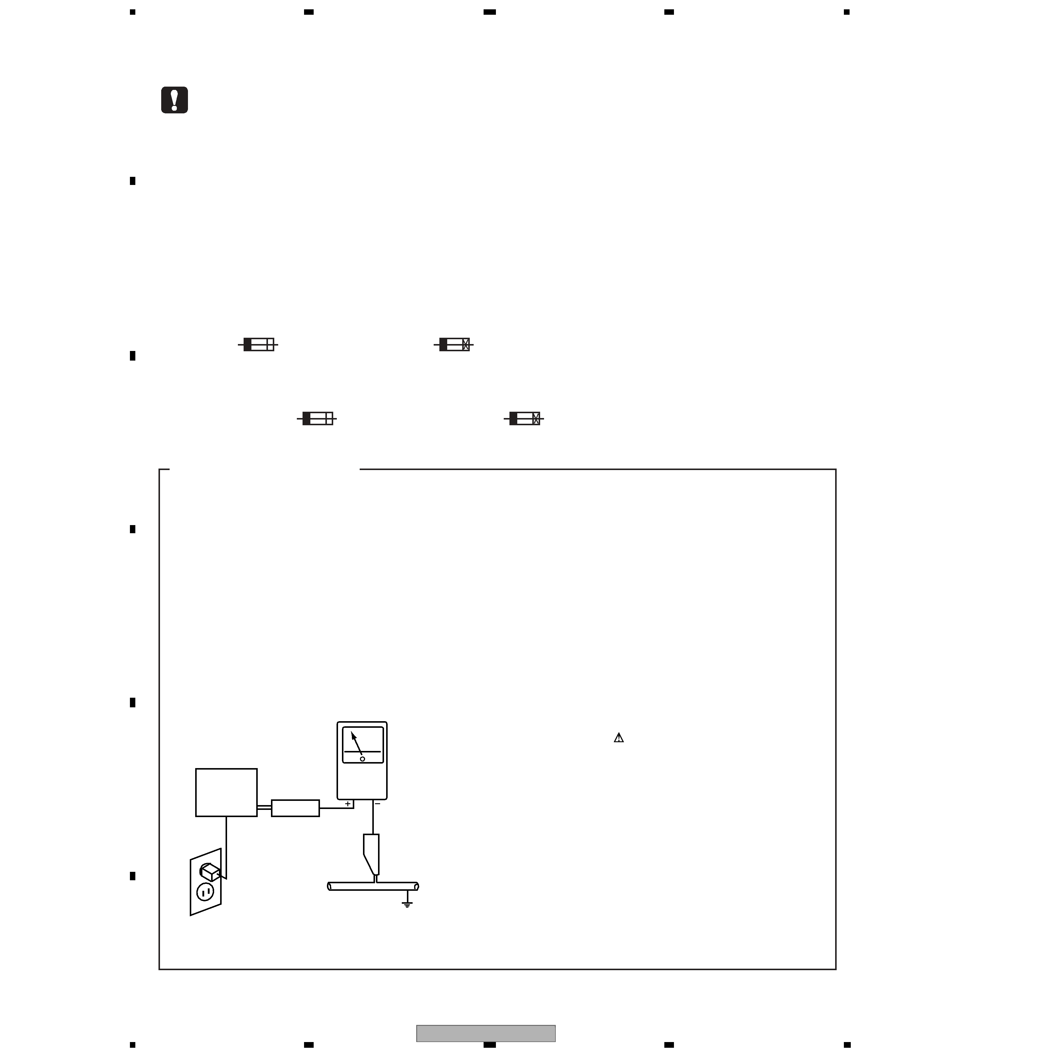
LEAKAGE CURRENT CHECK
Measure leakage current to a known earth ground (water
pipe, conduit, etc.) by connecting a leakage current tester
such as Simpson Model 229-2 or equivalent between the
earth ground and all exposed metal parts of the appliance
(input/output terminals, screwheads, metal overlays, control
shaft, etc.). Plug the AC line cord of the appliance directly
into a 120V AC 60Hz outlet and turn the AC power switch
on. Any current measured must not exceed 0.5mA.
(FOR USA MODEL ONLY)
Leakage
current
tester
Reading should
not be above
0.5mA
Device
under
test
Test all
exposed metal
surfaces
Also test with
plug reversed
(Using AC adapter
plug as required)
Earth
ground
AC Leakage Test
PRV-LX1
3
5
678
56
7
8
C
D
F
A
B
E
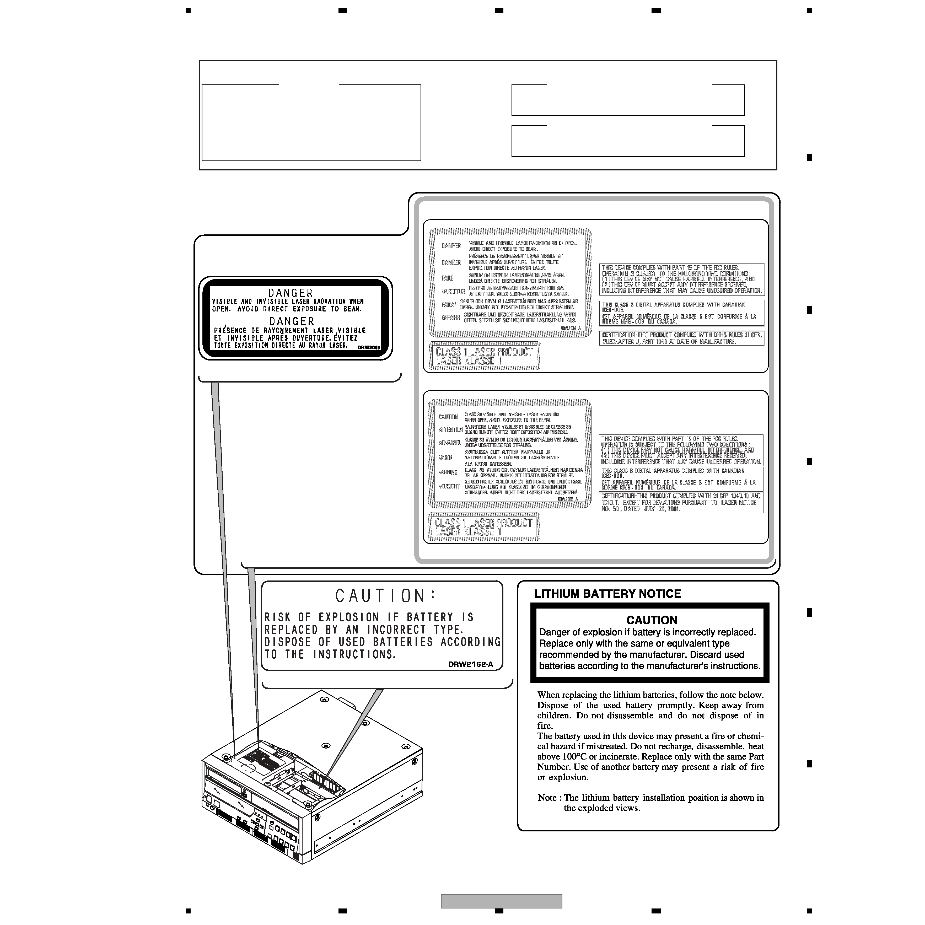
IMPORTANT
THIS
PIONEER
APPARATUS
CONTAINS
INVISIBLE LASER OF CLASS 3b and VISIBLE
LASER OF CLASS 2.
SERVICING OPERATION OF THE APPARATUS
SHOULD
BE
DONE
BY
A
SPECIALLY
INSTRUCTED PERSON.
LASER DIODE CHARACTERISTICS
MAXIMUM OUTPUT POWER: 25 mW
WAVELENGTH: 654 - 662 nm
LASER DIODE CHARACTERISTICS
MAXIMUM OUTPUT POWER: 36 mW
WAVELENGTH: 780 - 787 nm
LABEL CHECK
(DRW2109)
(DRW2185)
(DRW2162)
(DRW2069)
DRIVE Assy LX1
Note: You will see one of the following two labels attached.
PRV-LX1
4
1234
123
4
C
D
F
A
B
E
CONTENTS
1. SPECIFICATIONS ..............................................................................................................................................................6
1.1 SPECIFICATIONS CHECKS.................................................................................................................................6
1.2 FUNCTION MENU ..................................................................................................................................................8
1.3 SPECIFICATIONS................................................................................................................................................ 11
2. EXPLODED VIEWS AND PARTS LIST ....................................................................................................................... 14
2.1 DVD RECORDER (PRV-LX1) ................................................................................................................................ 14
2.1.1 PACKING ............................................................................................................................................................ 14
2.1.2 EXTERIOR SECTION (1/3) ............................................................................................................................ 16
2.1.3 EXTERIOR SECTION (2/3) ............................................................................................................................ 18
2.1.4 EXTERIOR SECTION (3/3) ............................................................................................................................ 20
2.1.5 REAR PANEL SECTION ................................................................................................................................. 22
2.1.6 FRONT PANEL SECTION............................................................................................................................... 24
2.2 DVD-R/RW WRITER UNIT ..................................................................................................................................... 26
2.2.1 PACKING ............................................................................................................................................................ 26
2.2.2 EXTERIOR SECTION ...................................................................................................................................... 27
[ Important symbols for good services ]
In this manual, the symbols shown-below indicate that adjustments, settings or cleaning should be made securely.
When you find the procedures bearing any of the symbols, be sure to fulfill them:
2. Adjustments
To keep the original performances of the product, optimum adjustments or specification confirmation is indispensable.
In accordance with the procedures or instructions described in this manual, adjustments should be performed.
3. Cleaning
For optical pickups, tape-deck heads, lenses and mirrors used in projection monitors, and other parts requiring cleaning,
proper cleaning should be performed to restore their performances.
5. Lubricants, glues, and replacement parts
Appropriately applying grease or glue can maintain the product performances. But improper lubrication or applying
glue may lead to failures or troubles in the product. By following the instructions in this manual, be sure to apply the
prescribed grease or glue to proper portions by the appropriate amount.For replacement parts or tools, the prescribed
ones should be used.
4. Shipping mode and shipping screws
To protect the product from damages or failures that may be caused during transit, the shipping mode should be set or
the shipping screws should be installed before shipping out in accordance with this manual, if necessary.
1. Product safety
You should conform to the regulations governing the product (safety, radio and noise, and other regulations), and
should keep the safety during servicing by following the safety instructions described in this manual.
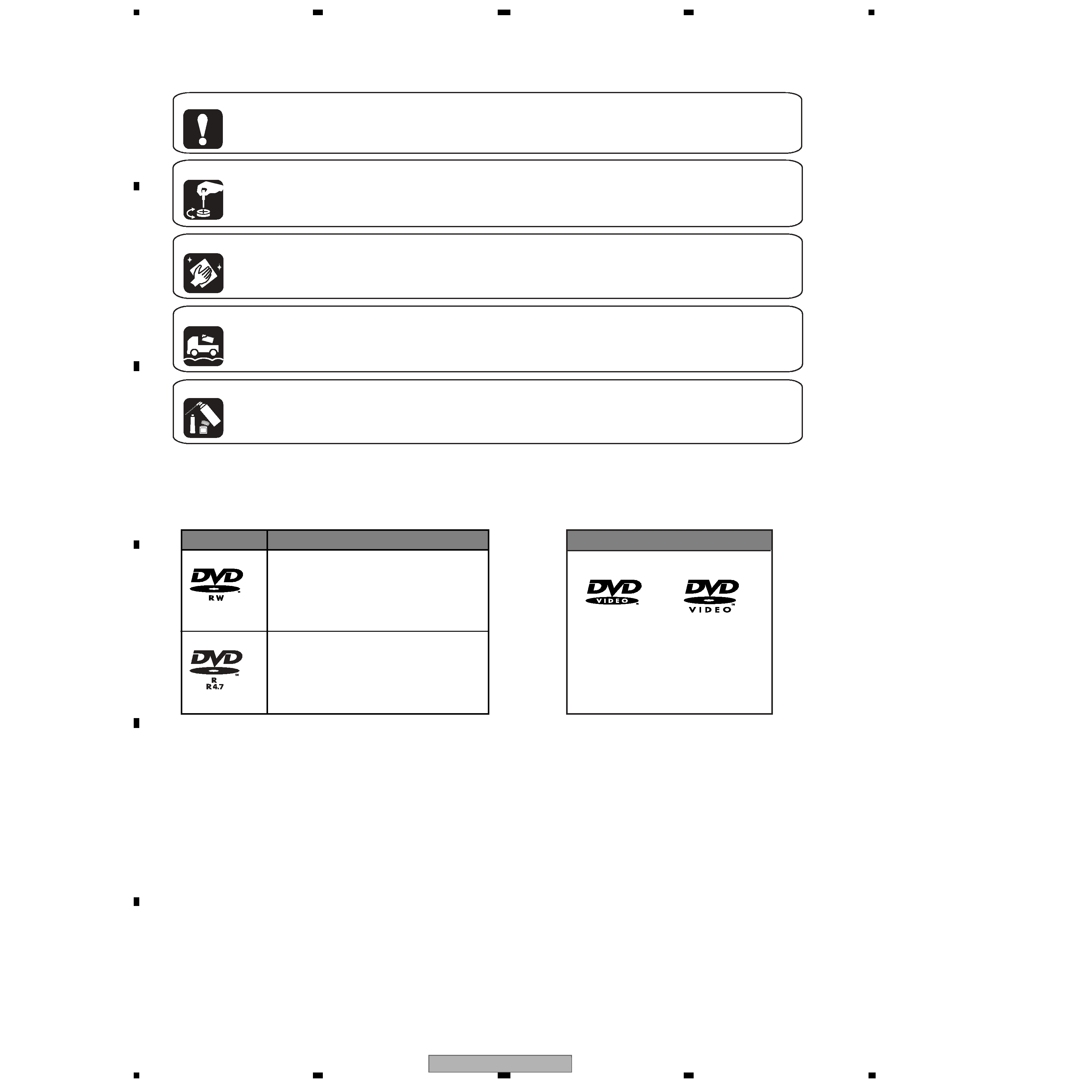
DVD video
DVD-RW
DVD-R
Logo
Logo
Attributes
12cm, single-sided, single layer disc
Approx. max. recording time: 360
minutes (4.7GB)
12cm, double-sided, single layer disc
Approx. max. recording time: 720
minutes (9.4GB)
DVD-RW
· Recordable discs
· Playback only discs
This unit does not support use of 8 cm DVD-R discs.
· CD-R/CD-RW discs cannot be recorded on this unit.

PRV-LX1
5
5
678
56
7
8
C
D
F
A
B
E
3. BLOCK DIAGRAM AND SCHEMATIC DIAGRAM ..................................................................................................... 28
3.1 BLOCK DIAGRAM.................................................................................................................................................... 28
3.1.1 OVERALL BLOCK DIAGRAM ......................................................................................................................... 28
3.1.2 I/O BLOCK.......................................................................................................................................................... 30
3.1.3 DECB ASSY ....................................................................................................................................................... 31
3.1.4 PCIB ASSY......................................................................................................................................................... 32
3.1.5 AVIB ASSY ......................................................................................................................................................... 33
3.1.6 PWRB, FLKB, KEYB, DRV1B, DRV2B and USBB ASSYS ....................................................................... 35
3.1.7 PWRB ASSY ...................................................................................................................................................... 36
3.1.8 WAVEFORMS .................................................................................................................................................... 37
3.2 OVERALL WIRING DIAGRAM ............................................................................................................................... 40
3.3 JKIB ASSY (1/3) ....................................................................................................................................................... 42
3.4 JKIB ASSY (2/3) ....................................................................................................................................................... 44
3.5 JKIB ASSY (3/3) ....................................................................................................................................................... 46
3.6 JKDB and 422IB ASSYS......................................................................................................................................... 48
3.7 HPVB and JKOB ASSYS ........................................................................................................................................ 50
3.8 DECB ASSY (1/2)..................................................................................................................................................... 52
3.9 DECB ASSY (2/2)..................................................................................................................................................... 54
3.10 PCIB ASSY (1/4) .................................................................................................................................................... 56
3.11 PCIB ASSY (2/4) .................................................................................................................................................... 58
3.12 PCIB ASSY (3/4) .................................................................................................................................................... 60
3.13 PCIB ASSY (4/4) .................................................................................................................................................... 62
3.14 AVIB ASSY (1/6)..................................................................................................................................................... 64
3.15 AVIB ASSY (2/6)..................................................................................................................................................... 66
3.16 AVIB ASSY (3/6)..................................................................................................................................................... 68
3.17 AVIB ASSY (4/6)..................................................................................................................................................... 70
3.18 AVIB ASSY (5/6)..................................................................................................................................................... 72
3.19 AVIB ASSY (6/6)..................................................................................................................................................... 74
3.20 PWRB ASSY ........................................................................................................................................................... 76
3.21 FLKB ASSY ............................................................................................................................................................. 78
3.22 KEYB ASSY ............................................................................................................................................................ 80
3.23 DRV1B and DRV2B ASSYS................................................................................................................................. 82
3.24 USBB ASSY ............................................................................................................................................................ 84
4. PCB CONNECTION DIAGRAM .................................................................................................................................... 85
4.1 JKIB, JKDB, 422IB and HPVB ASSYS ................................................................................................................. 86
4.2 DECB ASSYS ........................................................................................................................................................... 90
4.3 PCIB ASSY ................................................................................................................................................................ 92
4.4 AVIB ASSY ................................................................................................................................................................ 94
4.5 PWRB ASSY ............................................................................................................................................................. 98
4.6 FLKB, KEYB, DRV1B, DRV2B and USBB ASSYS........................................................................................... 100
4.7 JKOB ASSY ............................................................................................................................................................. 104
4.8 MOTHER BOARD ASSY....................................................................................................................................... 105
5. PCB PARTS LIST........................................................................................................................................................... 108
6. ADJUSTMENT ............................................................................................................................................................... 116
6.1 27MHz CLOCK ADJUSTMENT ........................................................................................................................... 116
7. GENERAL INFORMATION .......................................................................................................................................... 117
7.1 DIAGNOSIS ............................................................................................................................................................. 117
7.1.1 TESTMODE...................................................................................................................................................... 117
7.1.2 TEST MODE CODE........................................................................................................................................ 120
7.1.3 LED Specifications .......................................................................................................................................... 122
7.1.4 POWER-ON Sequence .................................................................................................................................. 125
7.1.5 How to Check the Error Log .......................................................................................................................... 128
7.1.6 Error Log Display ............................................................................................................................................. 130
7.1.7 Debugging Display Mode ............................................................................................................................... 134
7.1.8 List of BIOS Setting Value.............................................................................................................................. 137
7.1.9 Rewriting of the GUIDs................................................................................................................................... 139
7.1.10 Cautions on Handling the HDD................................................................................................................... 140
7.1.11 HDD Replacement Procedures .................................................................................................................. 142
7.1.12 How to check the HDD ...................................................................................................................143
7.1.13 Cleaning.......................................................................................................................................................... 143
7.1.14 How to Install the OS or Program............................................................................................................... 144
7.1.15 Troubleshooting.............................................................................................................................................. 146
7.1.16 DISASSEMBLY ..............................................................................................................................152
7.1.17 Region Setting of the DVD/RW Writer Unit (optional).....................................................................167
7.2 IC INFORMATION .................................................................................................................................................. 168
8. PANEL FACILITIES........................................................................................................................................................ 188