ORDER NO.
PIONEER CORPORATION 4-1, Meguro 1-chome, Meguro-ku, Tokyo 153-8654, Japan
PIONEER ELECTRONICS (USA) INC. P.O. Box 1760, Long Beach, CA 90801-1760, U.S.A.
PIONEER EUROPE NV Haven 1087, Keetberglaan 1, 9120 Melsele, Belgium
PIONEER ELECTRONICS ASIACENTRE PTE. LTD. 253 Alexandra Road, #04-01, Singapore 159936
PIONEER CORPORATION 2004
PRA-BD12
PRA-BD11
RRV2971
SDI AES/EBU INPUT BOARD
PRA-BD11
SDI AES/EBU OUTPUT BOARD
PRA-BD12
THIS MANUAL IS APPLICABLE TO THE FOLLOWING MODEL(S) AND TYPE(S).
This service manual should be used together with the following manual(s).
Model
Type
Power Requirement
Remarks
PRA-BD11
ZUCYV/WL
DC Power supply from other system
PRA-BD12
ZUCYV/WL
DC Power supply from other system
Model No.
Order No.
Remarks
PRV-LX1
RRV2803
DVD RECORDER
For details, refer to "Important symbols for good services".
T-ZZY JULY 2004 printed in Japan

PRA-BD11
2
12
34
12
3
4
C
D
F
A
B
E
SAFETY INFORMATION
This service manual is intended for qualified service technicians ; it is not meant for the casual do-it-
yourselfer. Qualified technicians have the necessary test equipment and tools, and have been trained
to properly and safely repair complex products such as those covered by this manual.
Improperly performed repairs can adversely affect the safety and reliability of the product and may
void the warranty. If you are not qualified to perform the repair of this product properly and safely, you
should not risk trying to do so and refer the repair to a qualified service technician.
WARNING
This product contains lead in solder and certain electrical parts contain chemicals which are known to the state of California to cause
cancer, birth defects or other reproductive harm.
Health & Safety Code Section 25249.6 Proposition 65
PRA-BD11
3
56
78
56
7
8
C
D
F
A
B
E
CONTENTS
1. SPECIFICATIONS .............................................................................................................................................4
2. EXPLODED VIEWS AND PARTS LIST.............................................................................................................6
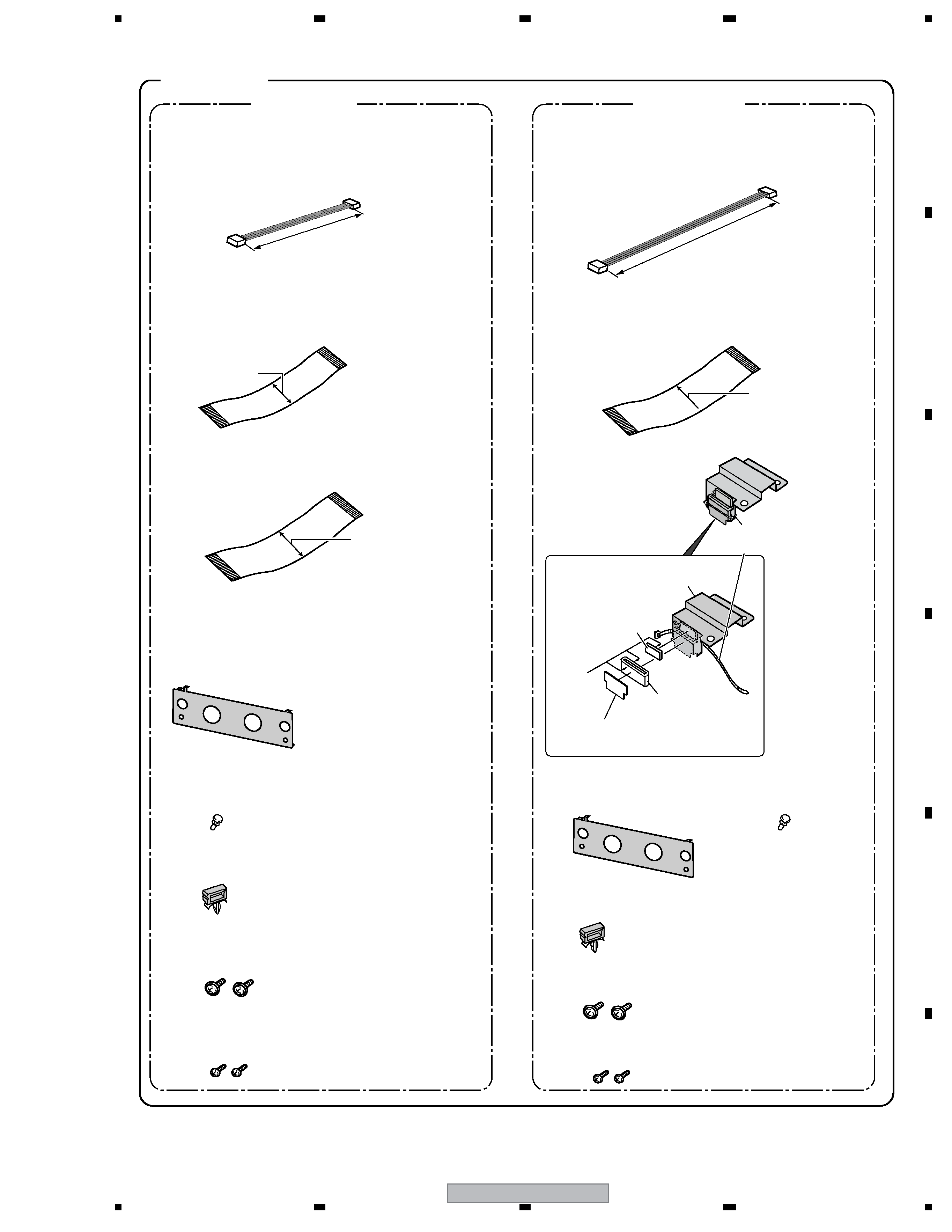
2.1 PACKING and EXTERIOR SECTION.........................................................................................................6
2.1.1 PRA-BD11 (SDI AES/ EBU INPUT BOARD ) ......................................................................................6
2.1.2 PRA-BD12 (SDI AES/ EBU OUTPUT BOARD) ...................................................................................8
3. BLOCK DIAGRAM AND SCHEMATIC DIAGRAM ..........................................................................................10
3.1 BLOCK DIAGRAM ....................................................................................................................................10
3.2 OVERALL CONNECTION DIAGRAM ......................................................................................................12
3.3 [PRA-BD11]: DINB ASSY (1/4).................................................................................................................14
3.4 [PRA-BD11]: DINB ASSY (2/4).................................................................................................................16
3.5 [PRA-BD11]: DINB ASSY (3/4).................................................................................................................18
3.6 [PRA-BD11]: DINB ASSY (4/4).................................................................................................................20
3.7 [PRA-BD12]: DOOB ASSY (1/2)...............................................................................................................22
3.8 [PRA-BD12]: DOOB ASSY (2/2)...............................................................................................................24
4. PCB CONNECTION DIAGRAM ......................................................................................................................26
5. PCB PARTS LIST ............................................................................................................................................30
6. ADJUSTMENT ................................................................................................................................................31
7. GENERAL INFORMATION .............................................................................................................................32
7.1 DIAGNOSIS ..............................................................................................................................................32
7.1.1 [PRA-BD11]: HOW TO OPERATION CHECK ....................................................................................32
7.1.2 [PRA-BD11]: LIST OF STATUS LED INDICATION ............................................................................37
7.1.3 [PRA-BD11]: EXTERNAL I/F SPECIFICATIONS ...............................................................................38
7.1.4 [PRA-BD11]: TROUBLESHOOTING ..................................................................................................39
7.1.5 [PRA-BD12]: HOW TO OPERATION CHECK ....................................................................................45
7.1.6 [PRA-BD12]: LIST OF STATUS LED INDICATION ............................................................................48
7.1.7 [PRA-BD12]: TEST MODE .................................................................................................................50
7.1.8 [PRA-BD12]: OPERATION CHECK OF THE ASSY ...........................................................................51
7.1.9 [PRA-BD12]: TROUBLESHOOTING ..................................................................................................52
7.1.10 DISASSEMBLY ................................................................................................................................59
7.1.11 INSTALLATION.................................................................................................................................60
7.2 IC INFORMATION ....................................................................................................................................70
8. PANEL FACILITIES .........................................................................................................................................96
[ Important symbols for good services ]
In this manual, the symbols shown-below indicate that adjustments, settings or cleaning should be made securely.
When you find the procedures bearing any of the symbols, be sure to fulfill them:
2. Adjustments
To keep the original performances of the product, optimum adjustments or specification confirmation is indispensable.
In accordance with the procedures or instructions described in this manual, adjustments should be performed.
3. Cleaning
For optical pickups, tape-deck heads, lenses and mirrors used in projection monitors, and other parts requiring cleaning,
proper cleaning should be performed to restore their performances.
5. Lubricants, glues, and replacement parts
Appropriately applying grease or glue can maintain the product performances. But improper lubrication or applying
glue may lead to failures or troubles in the product. By following the instructions in this manual, be sure to apply the
prescribed grease or glue to proper portions by the appropriate amount.For replacement parts or tools, the prescribed
ones should be used.
4. Shipping mode and shipping screws
To protect the product from damages or failures that may be caused during transit, the shipping mode should be set or
the shipping screws should be installed before shipping out in accordance with this manual, if necessary.
1. Product safety
You should conform to the regulations governing the product (safety, radio and noise, and other regulations), and
should keep the safety during servicing by following the safety instructions described in this manual.

PRA-BD11
4
12
34
12
3
4
C
D
F
A
B
E
1. SPECIFICATIONS
[PRA-BD11]
SDI input connectors:
Connector configuration ................ BNC (1)
Input impedance ............................. 75
Supported video standard .............. SMPTE 259 M-C compliant
(270 Mb/S, 525i/625i 4:2:2 component input)
Supported audio standard .............. SMPTE 272 M compliant
(Linear PCM, 48 kHz, 20-bit, channel 1/2) *1, *2, *3
AES/EBU input connectors:
Connector configuration ................. BNC (1)
Input impedance ............................. 75
Supported audio standard .............. AES-3ID-1995 compliant (Linear PCM, 48 kHz, 16/18/20 bit, industrial format)
1,3, 4
General:
Power supply ................................. +5 V DC (supplied internally by PRV-LX1)
Weight ........................................... 0.3 kg
Dimensions .................................... 195.5 (W) x 101 (D) x 28.4 (H) mm (including projections)
Ambient operating temperature ..... +5 to +35
°C (PRV-LX1 it mounts)
Ambient operating humidity ........... 5 to 85 % RH (no condensation)
1 Quantization bits input to the PRV-LX1 are converted to 16 bits.
2 Audio channel 3/4 input is not supported.
SDI audio can only be selected during SDI video input (audio only cannot be selected).
3 Compressed audio cannot be input.
4 Digital audio input of the CP-1201 consumer format is not supported.
[PRA-BD12]
SDI output connectors:
1
Connector configuration ................. BNC (1)
Output impedance .......................... 75
Supported video standard .............. SMPTE 259 M-C compliant
(270 Mb/S, 525i/625i 4:2:2 component output)
Supported audio standard ............. SMPTE 272 M compliant
(Linear PCM, 48 kHz, 20-bit, channel 1/2)
2, 3
AES/EBU output connectors :
1
Connector configuration .................. BNC (1)
Output impedance ........................... 75
Supported audio standard ............... AES-3ID-1995 compliant
(Linear PCM, 48 kHz industrial format)
2, 3
General:
Power supply .................................. +5 V DC (supplied internally by PRV-LX1)
Weight ............................................ 0.3 kg
Dimensions ...................................... 195.5 (W) x 101 (D) x 28.4 (H) mm (including projections)
Ambient operating temperature ...... +5 to +35
°C (PRV-LX1 it mounts)
Ambient operating humidity ............ 5 to 85% RH (no condensation)
1 Video/audio data is not output when playing back content containing signals preventing unauthorized copying to protect
copyright holders, etc.
The PRA-BD12 does not support through output of SDI and AES/EBU signals via the PRA-BD11 (SDI AES/EBU input
board).
2 Compressed audio cannot be output.
3 Output of the CP-1201 consumer format is not supported.
· Specifications and design are subject to possible modification without notice.
PRA-BD11
5
56
78
56
7
8
C
D
F
A
B
E
(DDD1267)
(DDD1266)
(DKP3673)
(DKP3674)
(26pin)
(30pin)
· 4-pin cable (M)
· 4-pin cable (L)
Short cable (1pin color : White)
(approx. 90 mm)
Long cable (1pin color : Blue)
(approx. 130mm)
· FFC cable (M)
(DDD1267)
· FFC cable (L)
· FFC cable (L)
Narrow
Wide
(30pin)
Wide
Accessories
PRA-BD11
PRA-BD12
· IN Terminal Cover..1
(DNF1692)
· OUT Terminal Cover..1
(DNF1693)
Cushion
(DEC2716)
Cable Support
(DNG1090)
Binder
(ZCA-SKB90BK)
Ferrite Core
(DTH1188)
Cable Sheet
(DEC2710)
· Operating Instructions
(DRC1218)
· Warranty Card
(For Japan)
· Warranty Card PUSA2
· Board Connection Caution
(DRY1224)
· OPB User Sheet
(For U.S.)
(DRY1228)
· Screw..x2
(PMB40P070FCU)
· Screw..x2
(BMZ30P060FNI)
· Screw..x2
(PMB40P070FCU)
· Screw..x2
(BMZ30P060FNI)
· Nyron Rivet...x1
(DEC2698)
· Nyron Rivet...x1
(DEC2698)
· Operating Instructions
(DRC1218)
· Warranty Card
(For Japan)
· Warranty Card PUSA2
· Board Connection Caution
(DRY1224)
· OPB User Sheet
(For U.S.)
(DRY1228)
· Locking Wire Saddle..x1
(DEC1305)
· Locking Wire Saddle..x1
(DEC1305)
Double-sided
tape side