ORDER NO.
PIONEER CORPORATION 4-1, Meguro 1-chome, Meguro-ku, Tokyo 153-8654, Japan
PIONEER ELECTRONICS SERVICE, INC. P.O. Box 1760, Long Beach, CA 90801-1760, U.S.A.
PIONEER ELECTRONIC (EUROPE) N.V. Haven 1087, Keetberglaan 1, 9120 Melsele, Belgium
PIONEER ELECTRONICS ASIACENTRE PTE. LTD. 253 Alexandra Road, #04-01, Singapore 159936
PIONEER CORPORATION 1999
c
ZY
AC230V Adapter or Battery pack
ZU/CA
AC120V Adapter or Battery pack
ZL
AC230V Adapter or Battery pack
PDV-LC10
RRV2212
1. SAFETY INFORMATION ...................................... 2
2. EXPLODED VIEWS AND PARTS LIST ................ 4
3. BLOCK DIAGRAM AND SCHEMATIC DIAGRAM .. 12
4. PCB CONNECTION DIAGRAM .......................... 31
5. PCB PARTS LIST ............................................... 38
6. ADJUSTMENT .................................................... 42
CONTENTS
T ZZR SEPT. 1999 Printed in Japan
THIS MANUAL IS APPLICABLE TO THE FOLLOWING MODEL(S) AND TYPE(S).
PORTABLE DVD PLAYER
Type
Power Requirement
Remarks
Model
PDV-LC10
DIGITAL OUT (OPTICAL)
PHONES
HOLD
ON/OFF
COLOR
BRIGHT
MONITOR
7. GENERAL INFORMATION ................................ 44
7.1 DIAGNOSIS ................................................. 44
7.1.1 DISASSEMBLY ...................................... 44
7.1.2 TROUBLE SHOOTING .......................... 47
7.2 PARTS ......................................................... 48
7.2.1 IC ............................................................ 48
7.2.2 DISPLAY ..................................................... 61
8. PANEL FACILITIES AND SPECIFICATIONS .... 62
PDV-LC10
2
1. SAFETY INFORMATION
1. SAFETY PRECAUTIONS
The following check should be performed for the
continued protection of the customer and service
technician.
ANY MEASUREMENTS NOT WITHIN THE LIMITS
OUTLINED ABOVE ARE INDICATIVE OF A PO-
TENTIAL SHOCK HAZARD AND MUST BE COR-
RECTED BEFORE RETURNING THE APPLIANCE
TO THE CUSTOMER.
2. PRODUCT SAFETY NOTICE
Many electrical and mechanical parts in the appli-
ance have special safety related characteristics. These
are often not evident from visual inspection nor the
protection afforded by them necessarily can be ob-
tained by using replacement components rated for
voltage, wattage , etc.
Replacement parts which have
these special safety
characteristics are identified in
this Service Manual.
Electrical components having such features are
identified by marking with a
on the schematics and
on the parts list in this Service Manual.
The use of a substitute replacement component which
does not have the same safety characteristics as the
PIONEER recommended replacement one, shown in
the parts list in this Service Manual, may create shock,
fire, or other hazards.
Product Safety is continuously under review and
new instructions are issued from time to time. For
the latest information, always consult the current
PIONEER Service Manual. A subscription to, or
ad-
ditional copies of, PIONEER Service Manual may be
obtained at a nominal charge from PIONEER.
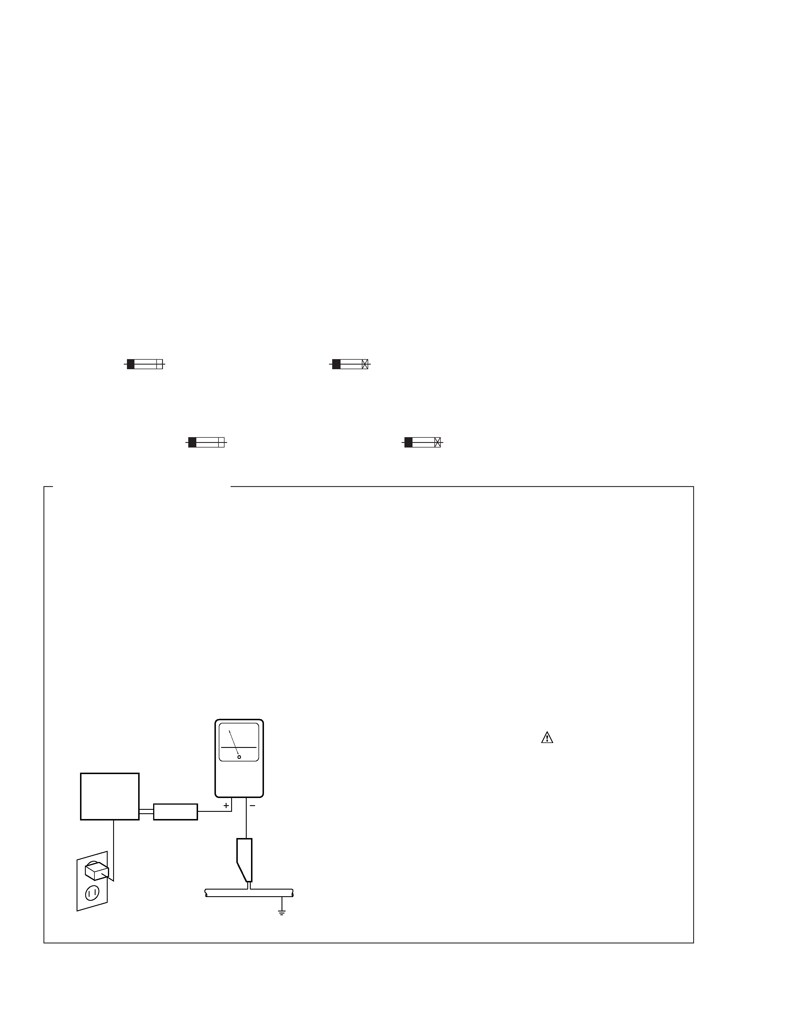
LEAKAGE CURRENT CHECK
Measure leakage current to a known earth ground
(water pipe, conduit, etc.) by connecting a leakage
current tester such as Simpson Model 229-2 or
equivalent between the earth ground and all exposed
metal parts of the appliance (input/output terminals,
screwheads, metal overlays, control shaft, etc.). Plug
the AC line cord of the appliance directly into a 120V
AC 60 Hz outlet and turn the AC power switch on. Any
current measured must not exceed 0.5 mA.
(FOR USA MODEL ONLY)
Also test with plug
reversed
(Using AC adapter
plug as required)
Device
under
test
Test all exposed
metal surfaces
Earth ground
Leakage
current
tester
Reading should
not be above
0.5 mA
AC Leakage Test
This service manual is intended for qualified service technicians; it is not meant for the casual
do-it-yourselfer. Qualified technicians have the necessary test equipment and tools, and have been
trained to properly and safely repair complex products such as those covered by this manual.
Improperly performed repairs can adversely affect the safety and reliability of the product and may
void the warranty. If you are not qualified to perform the repair of this product properly and safely, you
should not risk trying to do so and refer the repair to a qualified service technician.
WARNING
This product contains lead in solder and certain electrical parts contain chemicals which are known to the state of California to
cause cancer, birth defects or other reproductive harm.
Health & Safety Cod e Section 25249.6 Proposition 65
REMARQUE
(POUR MODÈLE CANADIEN SEULEMENT)
Les symboles de fusible
(fusible de type rapide) et/ou
(fusible de type lent) sur CCI indiquent que les
pièces de remplacement doivent avoir la même désignation.
NOTICE
(FOR CANADIAN MODEL ONLY)
Fuse symbols
(fast operating fuse) and/or
(slow operating fuse) on PCB indicate that replacement parts
must be of identical designation.
PDV-LC10
3
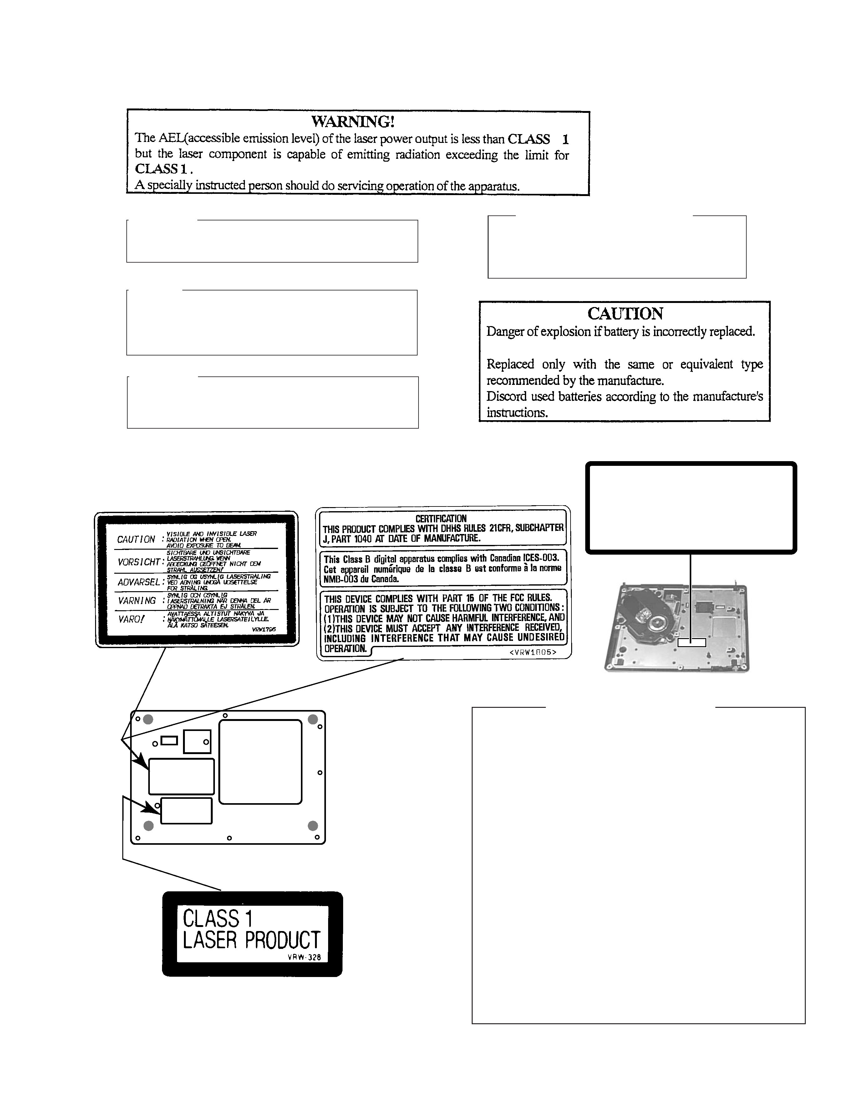
LABEL CHECK
ZY Type Only : VRW1796
ZY Type Only : VRW-328
VRW1805
ZU/CA Type Only :
To Reverse side
LABEL
Additional Laser Caution
1. Laser Interlock Mechanism
If the switch to detect door-open state (S603: DISC OPEN DET)
is open, the laser interlock mechanism operates and shuts down
the power source (Q100) to the laser diode drive circuit. The
system microcomputer detects this condition and does not issue
the Laser On command.
If Q100 is defective, accompanying a short-circuit between the
emitter and the collector, the system microcomputer judges this
status as the door-open state, and it does not issue the Laser
On command as long as Q611 is not defective, even if S603 is
open.
Therefore, the laser does not light unless S603 is intentionally
short-circuited in door-open state.
To light the laser in Test mode, short-circuit S603.
Hold S603 in the depressed position from the top, as it is a push
switch.
2. NEVER directly look at the objective lens from a short distance
when lighting the laser by short-circuiting S603 in door-open state.
CAUTION :
LASER RADIATION WHEN OPEN, AVOID LONG-TERM
VIEWING OF DIRECT LASER RADIATION.
CAUTION :
USE OF CONTROLS OR ADJUSTMENTS OR PER-
FORMANCE OF PROCEDURES OTHER THAN THOSE
SPECIFIED HEREIN MAY RESULT IN HAZARDOUS
RADIATION EXPOSURE.
LASER DIODE CHARACTERISTICS
FOR DVD : MAXIMUM OUTPUT POWER : 3.2 mw
WAVELENGTH : 650 nm
FOR CD :
MAXIMUM OUTPUT POWER : 3.3 mw
WAVELENGTH : 780 nm
CAUTION :
TO PREVENT RISK OF ELECTRIC SHOCK AND LASER
EXPOSURE, DISCONNECT THE AC ADAPTER OR THE
BATTERY BEFORE REMOVE SCREWS.
LASER RADIATION WHEN OPEN,
AVOID LONG-TERM VIEWING OF
DIRECT LASER RADIATION.
< VRW1815 >
CAUTION
ZU/CA type Only
: VRW1815
4
PDV-LC10
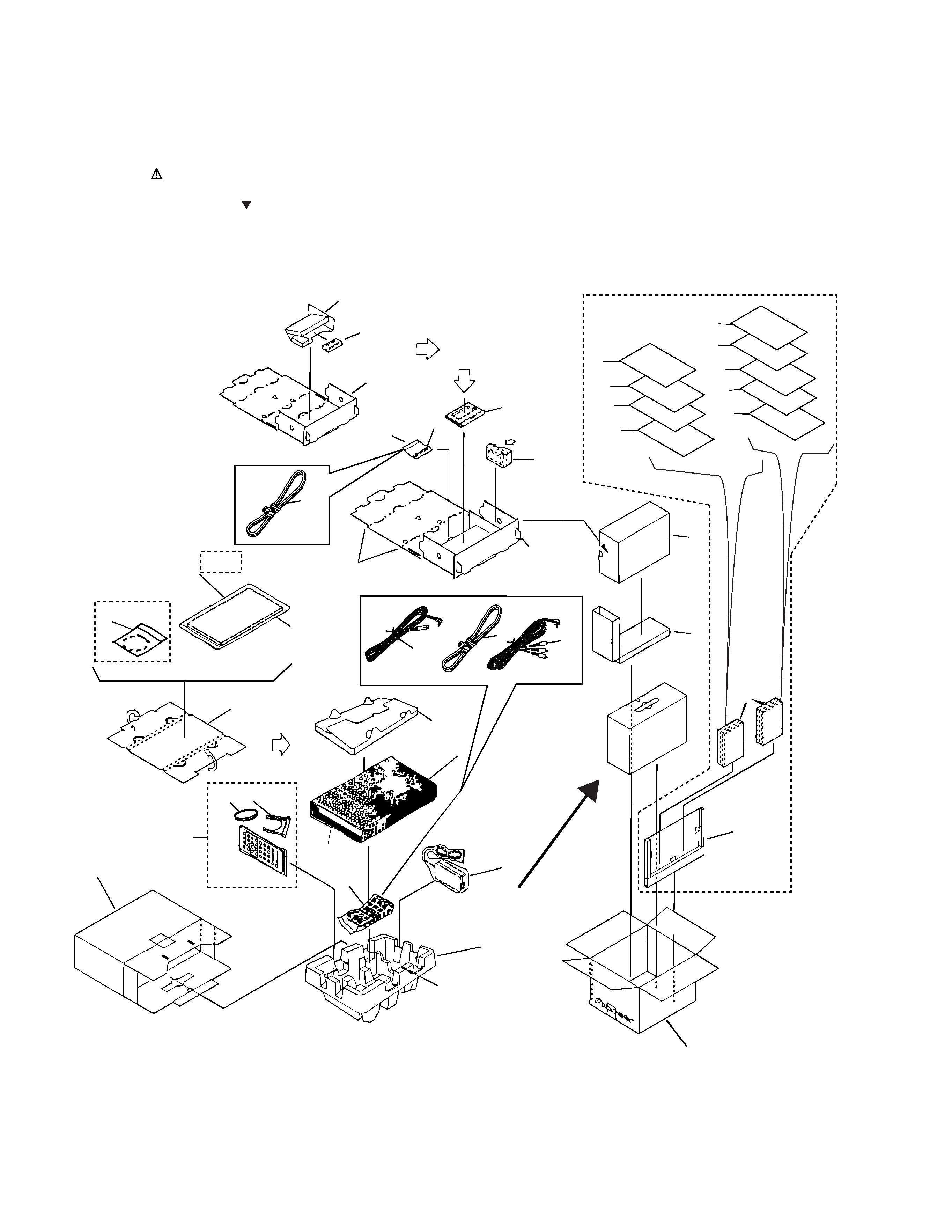
2.1 PACKING
2. EXPLODED VIEWS AND PARTS LIST
NOTES:
· Parts marked by "NSP" are generally unavailable because they are not in our Master Spare Parts List.
· The mark found on some component parts indicates the importance of the safety factor of the part.
Therefore, when replacing, be sure to use parts of identical designation.
· Screws adjacent to mark on the product are used for disassembly.
Top
Rear
PDV-LC10
Front mark
28
3
2
21
6
4
5
1
23
32
3
31
22
30
20
29
29
19
27
26
10
11
12
13
24
7
8
9
25
Accessory
14,15, 24, 25
18
16
17
16
6
3
ZU/CA, ZY Only
3
ZY Only
ZU/CA Only
33
5
PDV-LC10
2
AC Adapter
VWX1222
VWX1220
VXX2696
3
Polyethylene Bag
Z21-020
VHL1051
Z21-020
7
Operating Instructions (Dutch)
VRD1103
Not used
Not used
8
Operating Instructions (Swedish)
VRD1104
Not used
Not used
9
Operating Instructions (Spanish)
VRD1105
Not used
Not used
10
Operating Instructions (English)
VRB1241
Not used
Not used
11
Operating Instructions (French)
VRD1100
Not used
Not used
12
Operating Instructions (German)
VRD1102
Not used
Not used
13
Operating Instructions (ltalian)
VRD1101
Not used
Not used
14
Operating Instructions (English)
Not used
VRB1240
VRB1242
15
Operating Instructions (Chinese)
Not used
Not used
VRD1106
16
AC Power cord
ADG1127
RDG1034
ADG1127
19
Optical fiber Cable
VDE1062
VDE1062
Not used
23
Packing Carton
VHG1867
VHG1869
VHG1870
NSP
24
Warranty Card
ARY7022
ARY7023
Not used
NSP
25
Caution
VRM1076
VRM1076
Not used
32
Packing Plat
VHC1055
Not used
Not used
1
Tray
VHB1069
2
AC Adapter
See Contrast table (2)
3
Polyethylene Bag
See Contrast table (2)
4
Remote control unit
VXX2639
(CU-PDV003)
5
Battery Holder (Remote)
VNK4490
6
Packing Plat (Top)
VHC1045
7
Operating Instructions
See Contrast table (2)
8
Operating Instructions
See Contrast table (2)
9
Operating Instructions
See Contrast table (2)
10
Operating Instructions
See Contrast table (2)
11
Operating Instructions
See Contrast table (2)
12
Operating Instructions
See Contrast table (2)
13
Operating Instructions
See Contrast table (2)
14
Operating Instructions
See Contrast table (2)
15
Operating Instructions
See Contrast table (2)
16
AC Power cord
See Contrast table (2)
17
AV Cable
VDE1058
18
S-Video Cable
VDE1059
19
Optical fiber Cable
See Contrast table (2)
20
Battery Pack (NI-MH)
VEM1026
(1) PACKING PARTS LIST
Mark No.
Description
Part No.
Mark No.
Description
Part No.
21
Packing Case (Boby)
VHG1866
22
Packing Case (Battery)
VHG1868
23
Packing Carton
See Contrast table (2)
NSP
24
Warranty Card
See Contrast table (2)
NSP
25
Caution
See Contrast table (2)
26
Battery Charger
VWY1060
27
Battery Case
VXX2681
28
Mirror Mat Sheet
DHL1050
29
Pad A
VHB1072
30
Pad B
VHB1073
31
Packing Plat (Side)
VHC1054
32
Packing Plat
See Contrast table (2)
NSP
33
Lithium Battery(CR2025)
VEM1009
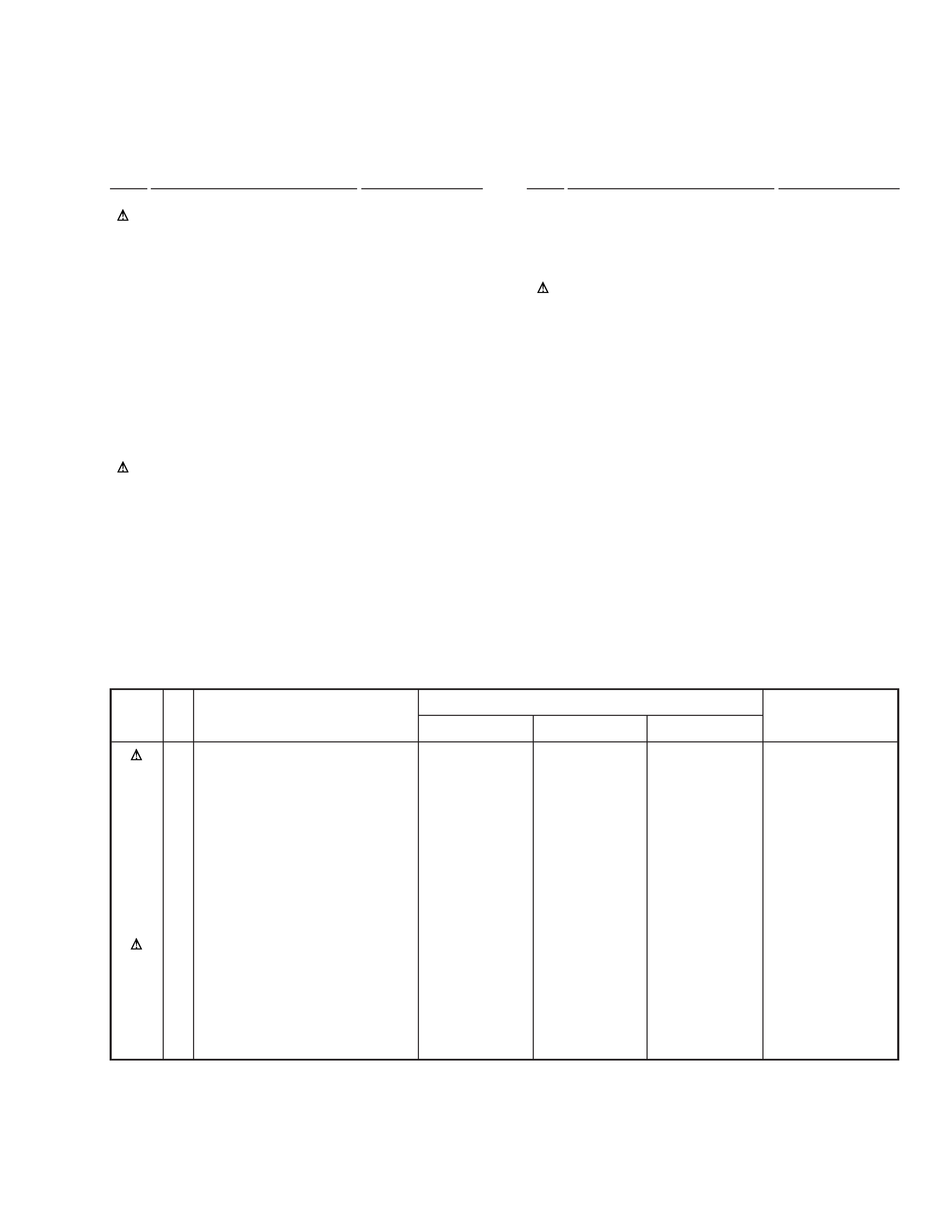
Part No.
Remarks
Mark
ZY type
ZU/CA type
ZL type
(2) CONTRAST TABLE
PDV-LC10/ZY, ZU/CA and ZL are constructed the same except for the following:
No.
Symbol and Description