ORDER NO.
PIONEER ELECTRONIC CORPORATION 4-1, Meguro 1-Chome, Meguro-ku, Tokyo 153-8654, Japan
PIONEER ELECTRONICS SERVICE, INC. P.O. Box 1760, Long Beach, CA 90801-1760, U.S.A.
PIONEER ELECTRONIC (EUROPE) N.V. Haven 1087, Keetberglaan 1, 9120 Melsele, Belgium
PIONEER ELECTRONICS ASIACENTRE PTE. LTD. 501 Orchard Road, #10-00 Wheelock Place, Singapore 238880
PIONEER ELECTRONIC CORPORATION 1998
MY
AC220230V
MV
AC220230V
SD
AC110V/120-127V/220-230V/240V
With the voltage selector
HPW
AC230 240V
COMPACT DISC PLAYER
RRV1981
TZZR JULY 1998 Printed in Japan
PD-S707
CONTENTS
1. SAFETY INFORMATION .................................... 2
2. EXPLODED VIEWS AND PARTS LIST ............. 3
3. SCHEMATIC DIAGRAM ................................... 12
4. PCB CONNECTION DIAGRAM ....................... 19
5. PCB PARTS LIST ............................................. 26
6. ADJUSTMENT .................................................. 30
7. GENERAL INFORMATION .............................. 38
7.1 IC ................................................................ 38
7.2 DISPLAY .................................................... 39
7.3 BLOCK DIAGRAM ..................................... 40
8. PANEL FACILITIES AND SPECIFICATIONS
................................................................... 41
THIS MANUAL IS APPLICABLE TO THE FOLLOWING MODEL(S) AND TYPE(S).
Power Requirement
Type
Model
PD-S707
The voltage can be converted by the following method.
8
3
1¡
7
STABLE PLATTER MECHANISM
Î
'
POWER
-- OFF _ ON
÷ COMPU
÷ ÷ AUTO
OFF
COMPACT DISC PLAYER
Hi-bit Legato Link Conversion
REPEAT
Û¿?
EDIT
DIGITAL
OUTPUT
DISPLAY
PHONES LEVEL
MIN
MAX
PHONES
4¢
0 OPEN/CLOSE
OUTPUT LEVEL
1¡
4
¢
78
3
Î
'
COMPACT DISC PLAYER
REMOTE CONTROL UNIT
CU-P0092
PROGRAM
HI-LITE
RANDOM
3
4
1
2
7
8
5
6
11
12
9
10
15
16
13
14
19
20
17
18
+
> 20
PD-S707
2
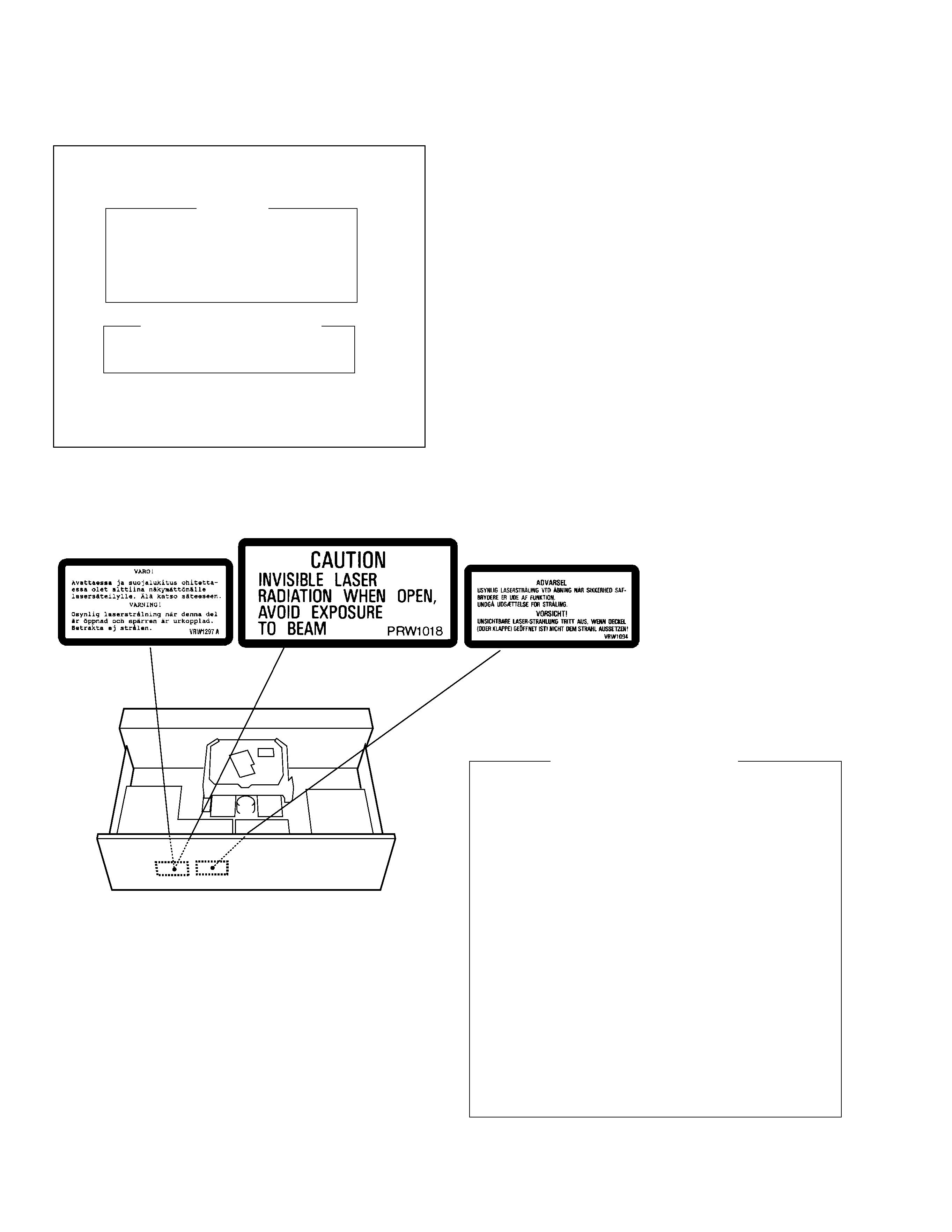
1. Laser Interlock Mechanism
The position of the switch (S601) for detecting loading
state is detected by the system microprocessor, and the
design prevents laser diode oscillation when the switch
(S601) is not on CLMP terminal side (CLMP signal is OFF
or high level.). Thus, the interlock will no longer function if
the switch (S601) is deliberately set to CLMP terminal
side (low level).
The interlock also does not function in the test mode
.
Laser diode oscillation will continue, if pin 33 of
CXA1782CQ (IC151) on the MAIN BOARD ASSY is
connected to GND, or pin 22 of IC301(LDON) is
connected to low level (ON), or else the terminals of Q151
are shorted to each other (fault condition).
2. When the cover is opened with the servo mechanism
block removed and turned over, close viewing of the
objective lens with the naked eye will cause exposure to a
Class 1 laser beam.
MY type
MV and HPW types
MY type
REAR
1. SAFETY INFORMATION
IMPORTANT
THIS PIONEER APPARATUS CONTAINS
LASER OF CLASS 1.
SERVICING OPERATION OF THE APPARATUS
SHOULD BE DONE BY A SPECIALLY
INSTRUTED PERSON.
LASER DIODE CHARACTERISTICS
MAXIMUM OUTPUT POWER: 5 mw
WAVELENGTH: 780 785 nm
Refer to page 31 .
LABEL CHECK
Additional Laser Caution
PD-S707
3
3
Packing Case S707
PHG2321
PHG2328
PHG2327
PHG2327
8
Operating Instructions
PRD1032
Not used
Not used
Not used
(Italian/Dutch/ Swedish/ Portouguese)
8
Operating Instructions (Chinese)
Not used
Not used
PRD1030
Not used
NSP
11
Warranty Card
ARY7022
ARY7008
Not used
ARY7022
12
V Spacer
Not used
PHC1089
Not used
Not used
NSP
13
Caution 220V Card
Not used
Not used
ARR7003
Not used
14
Control Cable
Not used
Not used
Not used
PDE1247
16
Polyethylene Bag
Not used
Z21- 013
Not used
Not used
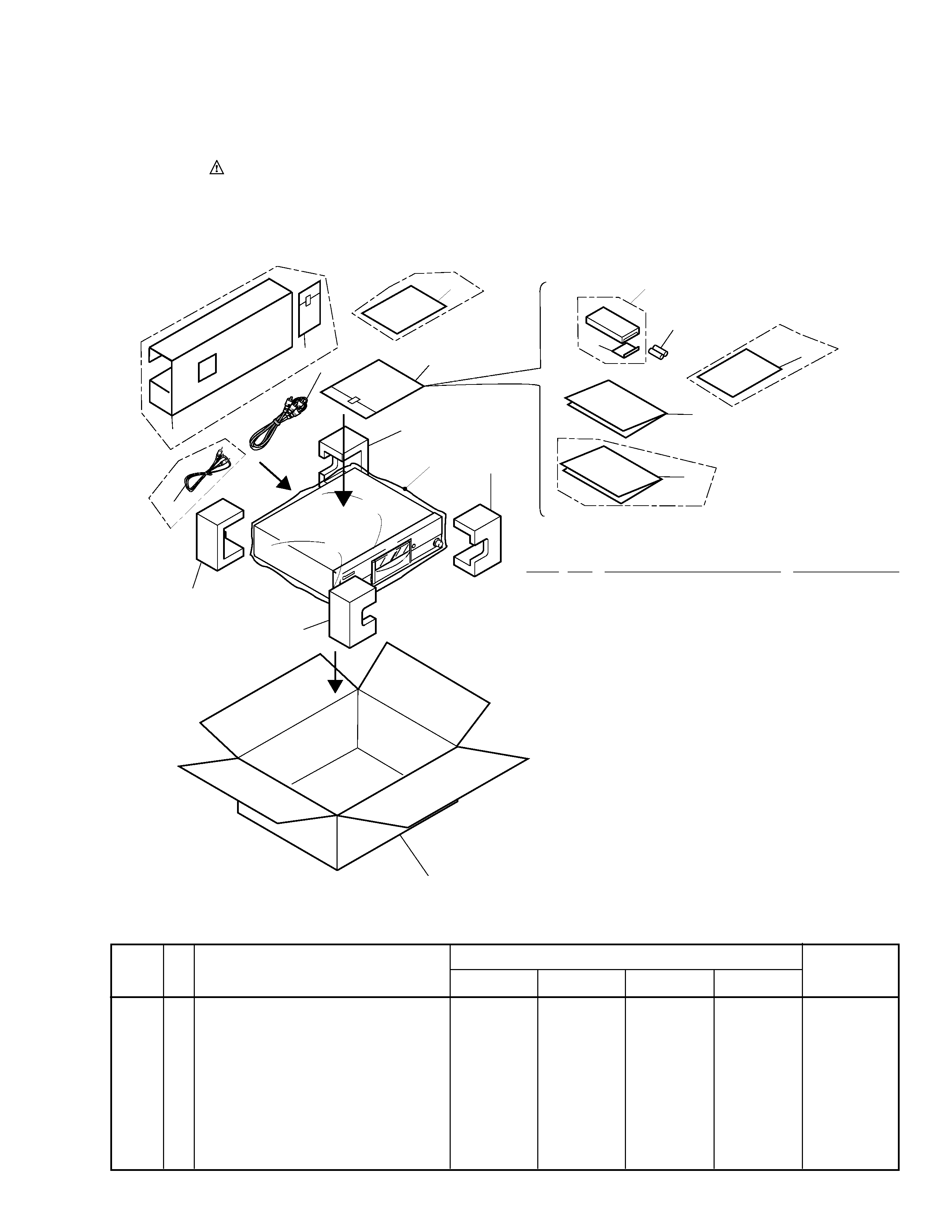
2. EXPLODED VIEWS AND PARTS LIST
2.1 PACKING
(1)PACKING PARTS LIST
1
Styrol Protector (F)
PHA1319
2
Styrol Protector (R)
PHA1320
3
Packing Case
See Contrast table(2)
4
Seat (750
× 600 × 0.5)
Z23007
5
Output Cable (L=1.2 m)
PDE1248
6
Remote Control Unit
PWW1143
(CU-PD097)
7
Battery Cover
PZN1103
8
Operating Instructions
See Contrast table(2)
NSP
9
Dry Cell Battery (R03, AAA)
VEM022
10
Polyethylene Bag
Z21038
(0.03
× 230 × 340)
NSP
11
Warranty Card
See Contrast table(2)
12
V Spacer
See Contrast table(2)
NSP
13
Caution 220V Card
See Contrast table(2)
14
Control Cable (for SR) (L=1m)
See Contrast table(2)
15
Operating Instructions
PRE1268
Mark No.
Description
Parts No.
Mark
(2) CONTRAST TABLE
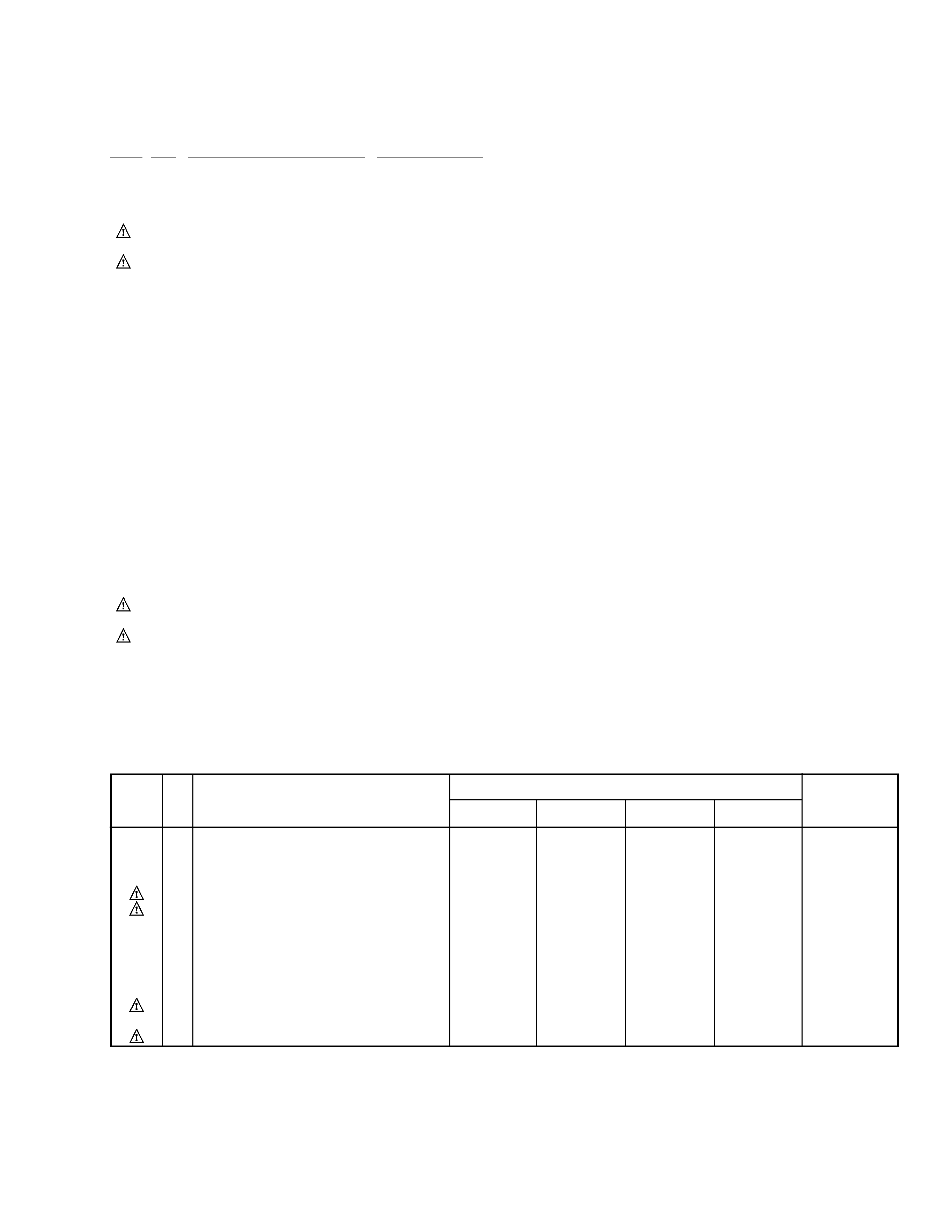
PD-S707/MY, MV, SD and HPW are constructed the same except for the following:
Remarks
Part No.
MY type
MV type
SD type
HPW type
Symbol and Description
No.
NOTES :
÷ Parts marked by " NSP " are generally unavailable because they are not in our Master Spare Parts List.
÷ The
mark found on some component parts indicates the importance of the safety factor of the part.
Therefore, when replacing, be sure to use parts of identical designation.
÷ Screw adjacent to
mark on the product are used for disassembly.
(English/ French/ German/Spanish)
16
Polyethylene Bag
See Contrast table(2)
7
6
9
14
11
15
3
8
5
10
13
4
12
1 (1/2)
1 (2/2)
2 (2/2)
2 (1/2)
16
Except
SD type Only
MY and SD types Only
MV
type
Only
HPW type Only
SD type
PD-S707
4
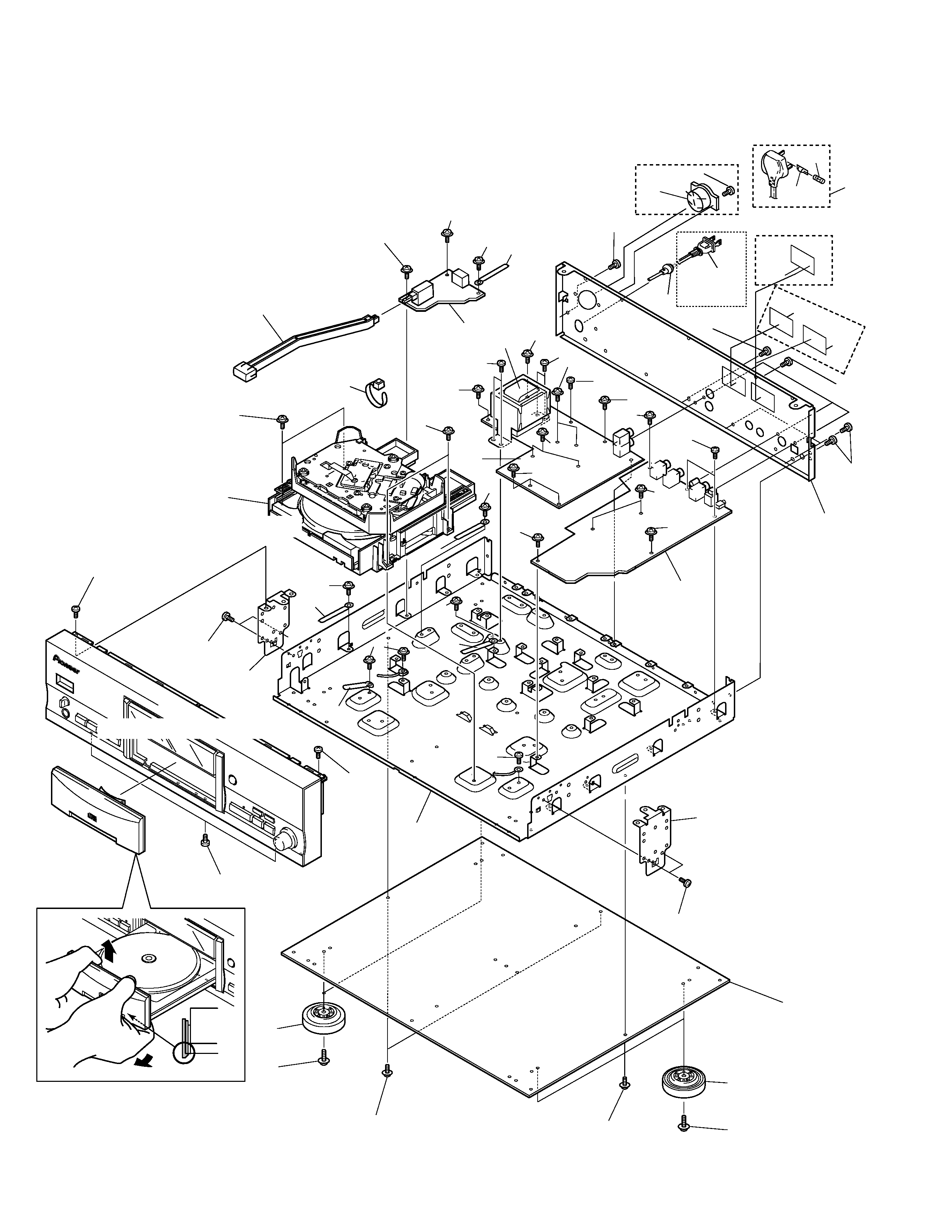
2.2 EXTERIOR (1/2)
1
2
1
7
8
18
19
17
25
19
9
10
11
22
11
10
20
12
20
20
20
13
15
16
6
3
17
17
17
18
18
18
18
17
18
18
22
22
20
18
18
18
18
Refer to " 2.3 EXTERIOR (2/2)".
Refer to " 2.4 LOADING
MECHANISM ASSY TT96".
14
18
18
18
18
18
18
24
24
18
18
23
22
2
18
18
18
5
24
24
24
5
4
SD type Only
MV and HPW types Only
26
Fuse Holder
MV type Only
MY
type
Only
Except MV
type
PD-S707
5
NSP
2
PRIMARY SWITCH ASSY
PWZ3869
PWZ3869
PWZ3870
PWZ3869
3
POWER BOARD ASSY
PWZ3800
PWZ3801
PWZ3802
PWZ3803
5
AC Power Cord
PDG1003
PDG1055
PDG1013
ADG1123
6
Power Transformer
PTT1301
PTT1301
PTT1302
PTT1301
8
Rear Base S707
PNA2433
PNA2447
PNA2448
PNA2449
14
Caution Label
Not used
PRW1018
Not used
PRW1018
15
Caution Label
VRW1094
Not used
Not used
Not used
NSP
16
Caution Label (HE)
VRW1297
Not used
Not used
Not used
25
Voltage Selector
Not used
Not used
AKX7001
Not used
26
Fuse (T5A)(For AC Power Cord)
Not used
PEK1003
Not used
Not used
(1) EXTERIOR (1/2) PARTS LIST
1
MAIN BOARD ASSY
See Contrast table(2)
NSP
2
PRIMARY SWITCH ASSY
See Contrast table(2)
3
POWER BOARD ASSY
See Contrast table(2)
4
Strain Relief
CM-22B
5
AC Power Cord
See Contrast table(2)
6
Power Transformer
See Contrast table(2)
NSP
7
Under Base
PNA2446
8
Rear Base S707
See Contrast table(2)
NSP
9
Bottom Plate
PNA2376
NSP
10
Side Angle
PNB1583
11
Insulator Assy
VXA2356
NSP
12
Loading Mechanism Assy TT96
PXA1611
13
Power Knob
PAC1897
14
Caution Label
See Contrast table(2)
15
Caution Label
See Contrast table(2)
NSP
16
Caution Label (HE)
See Contrast table(2)
17
Screw (3
×6)
ABA1207
18
Screw
ABA1011
19
Screw
BBZ30P080FZK
20
Screw
BBT30P080FCC
21
.............
22
Screw
IBZ30P100FCC
23
Binder
ZCA-SKB90BK
24
Cord Clamper
RNH184
25
Voltage Selector
See Contrast table(2)
26
Fuse (T5A)
See Contrast table(2)
Mark No.
Description
Parts No.
Mark
(2) CONTRAST TABLE
PD-S707/MY, MV, SD and HPW are constructed the same except for the following:
1
MAIN BOARD ASSY
PWZ3793
PWZ3794
PWZ3795
PWZ3796
Remarks
Part No.
MY type
MV type
SD type
HPW type
Symbol and Description
No.