ORDER NO.
PIONEER ELECTRONIC CORPORATION 4-1, Meguro 1-Chome, Meguro-ku, Tokyo 153-8654, Japan
PIONEER ELECTRONICS SERVICE, INC. P.O. Box 1760, Long Beach, CA 90801-1760, U.S.A.
PIONEER ELECTRONIC (EUROPE) N.V. Haven 1087, Keetberglaan 1, 9120 Melsele, Belgium
PIONEER ELECTRONICS ASIACENTRE PTE. LTD. 501 Orchard Road, #10-00 Wheelock Place, Singapore 238880
PIONEER ELECTRONIC CORPORATION 1998
RRV2032
T ZZY OCT. 1998 Printed in Japan
¶ Refer to the service manual RRV1983 for PDR-555RW/KU/CA.
THIS MANUAL IS APPLICABLE TO THE FOLLOWING MODEL(S) AND TYPE(S).
Model
PDR-V500
Type
KU/CA
PDR-V500
AC120V
COMPACT DISC RECORDER
Power Requirement
Remarks
PDR-V500
2
1. CONTRAST OF MISCELLANEOUS PARTS
Parts marked by "NSP" are generally unavailable because they are not in our Master Spare Parts List.
The
mark found on some component parts indicates the importance of the safety factor of the part.
Therefore, when replacing, be sure to use parts of identical designation.
Screws adjacent to
mark on product are used for disassembly.
Reference Nos. indicate the pages and Nos. in the service manual for the base model.
NOTES:
When ordering resistors, first convert resistance values into code form as shown in the following examples.
Ex.1 When there are 2 effective digits (any digit apart from 0), such as 560 ohm and 47k ohm (tolerance is shown by J=5%,
and K=10%).
Ex.2 When there are 3 effective digits (such as in high precision metal film resistors).
561
473
R50
1R0
5621
560
47k
0.5
1
RD1/4PU
J
RD1/4PU
J
RN2H
K
RS1P
K
56 x 101
47 x 103
R50
1R0
561
473
5.62k
RN1/4PC
F
562 x 101
5621
PDR-555RW/KU/CA and PDR-V500/KU/CA are constructed the same except for the following :
PACKING
P4 - 2
NSP
Warranty Card
ARY7023
DRY1177
P4 - 4
Operating Instructions (English)
PRB1270
PRB1279
P4 - 10
Packing Case
PHG2317
PHG2342
EXTERIOR SECTION
P6 - 17
Rear Base
PNA2428
PNA2458
P6 - 27
Power Button
PAC1877
PAC1918
FRONT PANEL SECTION
P7 - 7
Mode Button
PAC1873
PAC1910
P7 - 8
Manual Button L
PAC1874
PAC1911
P7 - 11
Manual Button R
PAC1878
PAC1912
P7 - 15
FL Sheet
PAM1756
PAM1762
P7 - 21
Front Panel
PNW2799
PNW2876
P7 - 22
Play Button
RAC2204
PAC1913
Part No.
PDR-555RW
/KU/CA
Ref. No.
Symbol and Description
Remarks
Mark
PDR-V500
/KU/CA
CONTRAST TABLE
ORDER NO.
PIONEER ELECTRONIC CORPORATION 4-1, Meguro 1-Chome, Meguro-ku, Tokyo 153-8654, Japan
PIONEER ELECTRONICS SERVICE, INC. P.O. Box 1760, Long Beach, CA 90801-1760, U.S.A.
PIONEER ELECTRONIC (EUROPE) N.V. Haven 1087, Keetberglaan 1, 9120 Melsele, Belgium
PIONEER ELECTRONICS ASIACENTRE PTE. LTD. 501 Orchard Road, #10-00 Wheelock Place, Singapore 238880
PIONEER ELECTRONIC CORPORATION 1998
c
PDR-555RW
RRV1983
1. SAFETY INFORMATION ...................................... 2
2. EXPLODED VIEWS AND PARTS LIST ................ 4
3. SCHEMATIC DIAGRAM ..................................... 10
4. PCB CONNECTION DIAGRAM .......................... 32
5. PCB PARTS LIST ............................................... 44
6. ADJUSTMENT .................................................... 49
CONTENTS
7. GENERAL INFORMATION ................................ 55
7.1 PARTS ......................................................... 55
7.1.1 IC ........................................................... 55
7.1.2 DISPLAY ................................................ 67
8. PANEL FACILITIES AND SPECIFICATIONS .. .69
T IZK OCT. 1998 Printed in Japan
Type
Model
Power Requirement
Remarks
PDR-555RW
KU/CA
AC120V
MY
AC220-230V
THIS MANUAL IS APPLICABLE TO THE FOLLOWING MODEL(S) AND TYPE(S).
COMPACT DISC RECORDER
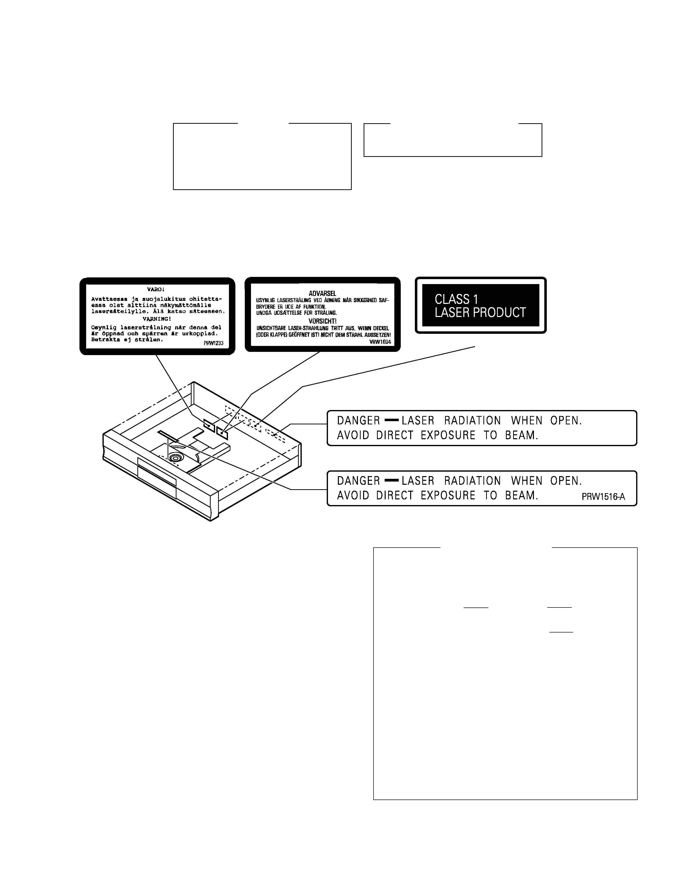
FOR U.S. MODELS
NECESSARY INFORMATION FOR DHHS
RULES MARKED ON THE REAR BASE AND ON
THE TOP OF CD MECHANISM AS BELOW.
DANGER LASER RADIATION WHEN OPEN.
AVOID DIRECT EXPOSURE TO BEAM.
· Refer to the service guide RRV2055 for PDR-555RW.
2
PDR-555RW
1. SAFETY INFORMATION
This service manual is intended for qualified service technicians ; it is not meant for the casual do-it-
yourselfer. Qualified technicians have the necessary test equipment and tools, and have been trained
to properly and safely repair complex products such as those covered by this manual.
Improperly performed repairs can adversely affect the safety and reliability of the product and may
void the warranty. If you are not qualified to perform the repair of this product properly and safely, you
should not risk trying to do so and refer the repair to a qualified service technician.
WARNING
This product contains lead in solder and certain electrical parts contain chemicals which are known to the state of California to cause
cancer, birth defects or other reproductive harm.
Health & Safety Code Section 25249.6 Proposition 65
NOTICE
(FOR CANADIAN MODEL ONLY)
Fuse symbols
(fast operating fuse) and/or
(slow operating fuse) on PCB indicate that replacement parts must
be of identical designation.
REMARQUE
(POUR MODÈLE CANADIEN SEULEMENT)
Les symboles de fusible
(fusible de type rapide) et/ou
(fusible de type lent) sur CCI indiquent que les pièces
de remplacement doivent avoir la même désignation.
ANY MEASUREMENTS NOT WITHIN THE LIMITS
OUTLINED ABOVE ARE INDICATIVE OF A POTENTIAL
SHOCK HAZARD AND MUST BE CORRECTED BEFORE
RETURNING THE APPLIANCE TO THE CUSTOMER.
2. PRODUCT SAFETY NOTICE
Many electrical and mechanical parts in the appliance
have special safety related characteristics. These are
often not evident from visual inspection nor the protection
afforded by them necessarily can be obtained by using
replacement components rated for voltage, wattage, etc.
Replacement parts which have these special safety
characteristics are identified in this Service Manual.
Electrical components having such features are identified
by marking with a
on the schematics and on the parts list
in this Service Manual.
The use of a substitute replacement component which does
not have the same safety characteristics as the PIONEER
recommended replacement one, shown in the parts list in
this Service Manual, may create shock, fire, or other hazards.
Product Safety is continuously under review and new
instructions are issued from time to time. For the latest
information, always consult the current PIONEER Service
Manual. A subscription to, or additional copies of, PIONEER
Service Manual may be obtained at a nominal charge from
PIONEER.
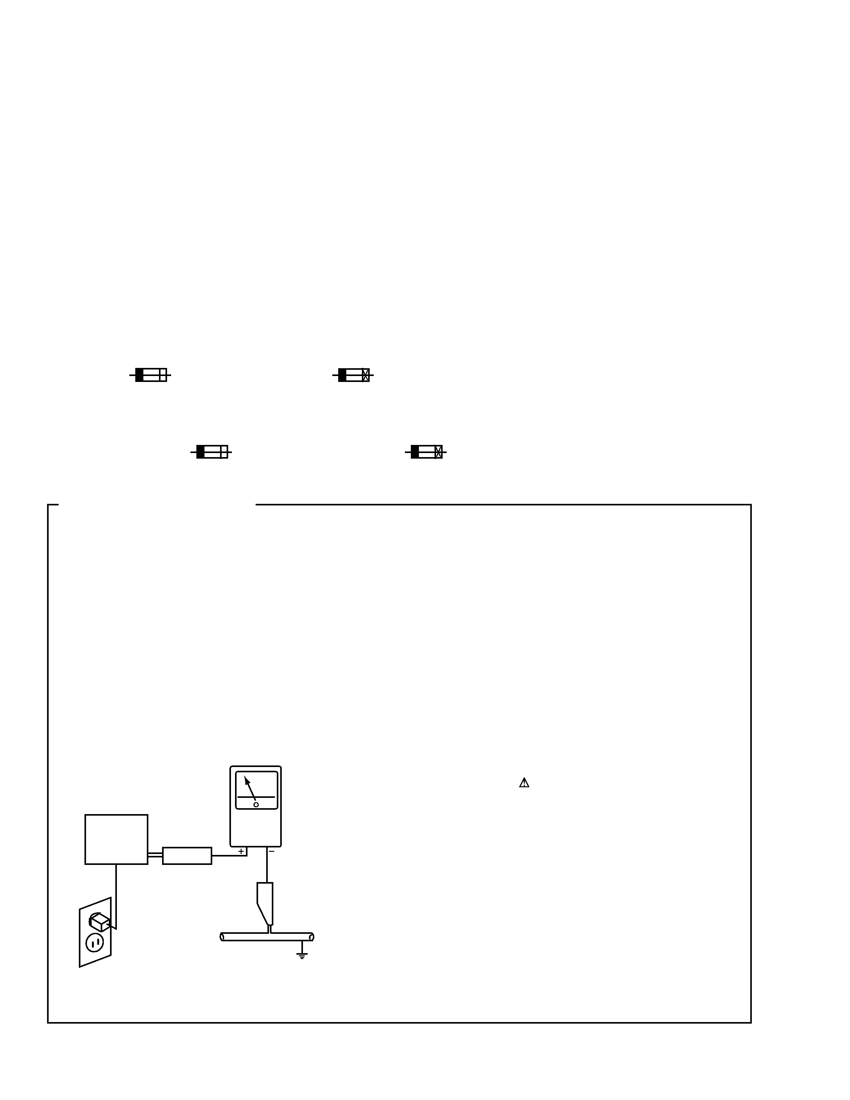
1. SAFETY PRECAUTIONS
The following check should be performed for the
continued protection of the customer and service
technician.
LEAKAGE CURRENT CHECK
Measure leakage current to a known earth ground (water
pipe, conduit, etc.) by connecting a leakage current tester
such as Simpson Model 229-2 or equivalent between the
earth ground and all exposed metal parts of the appliance
(input/output terminals, screwheads, metal overlays, control
shaft, etc.). Plug the AC line cord of the appliance directly
into a 120V AC 60Hz outlet and turn the AC power switch
on. Any current measured must not exceed 0.5mA.
(FOR USA MODEL ONLY)
Leakage
current
tester
Reading should
not be above
0.5mA
Device
under
test
Test all
exposed metal
surfaces
Also test with
plug reversed
(Using AC adapter
plug as required)
Earth
ground
AC Leakage Test
3
PDR-555RW
IMPORTANT
THIS PIONEER APPARATUS CONTAINS
LASER OF CLASS
b.
SERVICING OPERATION OF THE APPARATUS
SHOULD BE DONE BY A SPECIALLY
INSTRUTED PERSON.
LASER DIODE CHARACTERISTICS
MAXIMUM OUTPUT POWER: 23 mW
WAVELENGTH: 778 787 nm
1. Laser Interlock Mechanism
The position of the switch (S601) for detecting loading
state is detected by the system microprocessor, and the
design prevents laser diode oscillation when the switch
(S601) is not on CLMP terminal side (CLMP signal is OFF
or high level.). Thus, the interlock will no longer function if
the switch (S601) is deliberately set to CLMP terminal side
(low level).
The interlock also does not function in the test mode
.
Laser diode oscillation will continue, if pin 1 of M51593FP
(IC101) on the PRE-AMP BOARD ASSY mounted on the
pickup assembly is connected to GND, or pin 19 is
connected to low level (ON), or else the terminals of Q101
are shorted to each other (fault condition).
2. When the cover is opened with the servo mechanism
block removed and turned over, close viewing of the
objective lens with the naked eye will cause exposure to a
Class 1 laser beam.
Additional Laser Caution
Refer to page 49 .
LABEL CHECK
KU/CA type
Printed on Rear Panel
Printed on Rear Panel
MY Type
MY Type
MY Type