ORDER NO.
PIONEER CORPORATION 4-1, Meguro 1-chome, Meguro-ku, Tokyo 153-8654, Japan
PIONEER ELECTRONICS SERVICE, INC. P.O. Box 1760, Long Beach, CA 90801-1760, U.S.A.
PIONEER ELECTRONIC (EUROPE) N.V. Haven 1087, Keetberglaan 1, 9120 Melsele, Belgium
PIONEER ELECTRONICS ASIACENTRE PTE. LTD. 253 Alexandra Road, #04-01, Singapore 159936
PIONEER CORPORATION 1999
c
PDR-509
RRV2167
1. SAFETY INFORMATION ....................................... 2
2. EXPLODED VIEWS AND PARTS LIST ................. 4
3. BLOCK DIAGRAM AND SCHEMATIC DIAGRAM .. 10
4. PCB CONNECTION DIAGRAM ........................... 37
5. PCB PARTS LIST ................................................ 47
6. ADJUSTMENT ..................................................... 52
CONTENTS
7. GENERAL INFORMATION .................................. 58
7.1 DIAGNOSIS ................................................... 58
7.1.1 TROUBLE SHOOTING ............................ 58
7.1.2 DISASSEMBLY ........................................ 59
7.1.3 DIAGNOSIS OF CD-R CORE ASSY ........ 61
7.2 PARTS ........................................................... 62
7.2.1 IC ............................................................. 62
7.2.2 DISPLAY .................................................. 68
7.3 EXPLANATION .............................................. 70
7.3.1 ERROR CODE ......................................... 70
8. PANEL FACILITIES AND SPECIFICATIONS ....... 72
T IZE AUG. 1999 Printed in Japan
COMPACT DISC RECORDER
Type
Model
Power Requirement
Remarks
PDR-509
KU/CA
AC120V
MY
AC220-230V
MV
AC220-230V
THIS MANUAL IS APPLICABLE TO THE FOLLOWING MODEL(S) AND TYPE(S).
MONITOR
DIGITAL
REC LEVEL
ANALOG
REC LEVEL
INPUT
SELECTOR
TIME
REPEAT
This service manual should be used
together with the following manual (s).
FOR U.S. MODELS
NECESSARY INFORMATION FOR DHHS
RULES MARKED ON THE REAR BASE AND ON
THE TOP OF CD MECHANISM AS BELOW.
DANGER LASER RADIATION WHEN OPEN.
AVOID DIRECT EXPOSURE TO BEAM.
Model
Order No.
Remarks
PDR-509
RRV2055
Service guide
2
PDR-509
1. SAFETY INFORMATION
This service manual is intended for qualified service technicians ; it is not meant for the casual do-it-
yourselfer. Qualified technicians have the necessary test equipment and tools, and have been trained
to properly and safely repair complex products such as those covered by this manual.
Improperly performed repairs can adversely affect the safety and reliability of the product and may
void the warranty. If you are not qualified to perform the repair of this product properly and safely, you
should not risk trying to do so and refer the repair to a qualified service technician.
WARNING
This product contains lead in solder and certain electrical parts contain chemicals which are known to the state of California to cause
cancer, birth defects or other reproductive harm.
Health & Safety Code Section 25249.6 Proposition 65
NOTICE
(FOR CANADIAN MODEL ONLY)
Fuse symbols
(fast operating fuse) and/or
(slow operating fuse) on PCB indicate that replacement parts must
be of identical designation.
REMARQUE
(POUR MODÈLE CANADIEN SEULEMENT)
Les symboles de fusible
(fusible de type rapide) et/ou
(fusible de type lent) sur CCI indiquent que les pièces
de remplacement doivent avoir la même désignation.
ANY MEASUREMENTS NOT WITHIN THE LIMITS
OUTLINED ABOVE ARE INDICATIVE OF A POTENTIAL
SHOCK HAZARD AND MUST BE CORRECTED BEFORE
RETURNING THE APPLIANCE TO THE CUSTOMER.
2. PRODUCT SAFETY NOTICE
Many electrical and mechanical parts in the appliance
have special safety related characteristics. These are
often not evident from visual inspection nor the protection
afforded by them necessarily can be obtained by using
replacement components rated for voltage, wattage, etc.
Replacement parts which have these special safety
characteristics are identified in this Service Manual.
Electrical components having such features are identified
by marking with a
on the schematics and on the parts list
in this Service Manual.
The use of a substitute replacement component which does
not have the same safety characteristics as the PIONEER
recommended replacement one, shown in the parts list in
this Service Manual, may create shock, fire, or other hazards.
Product Safety is continuously under review and new
instructions are issued from time to time. For the latest
information, always consult the current PIONEER Service
Manual. A subscription to, or additional copies of, PIONEER
Service Manual may be obtained at a nominal charge from
PIONEER.
1. SAFETY PRECAUTIONS
The following check should be performed for the
continued protection of the customer and service
technician.
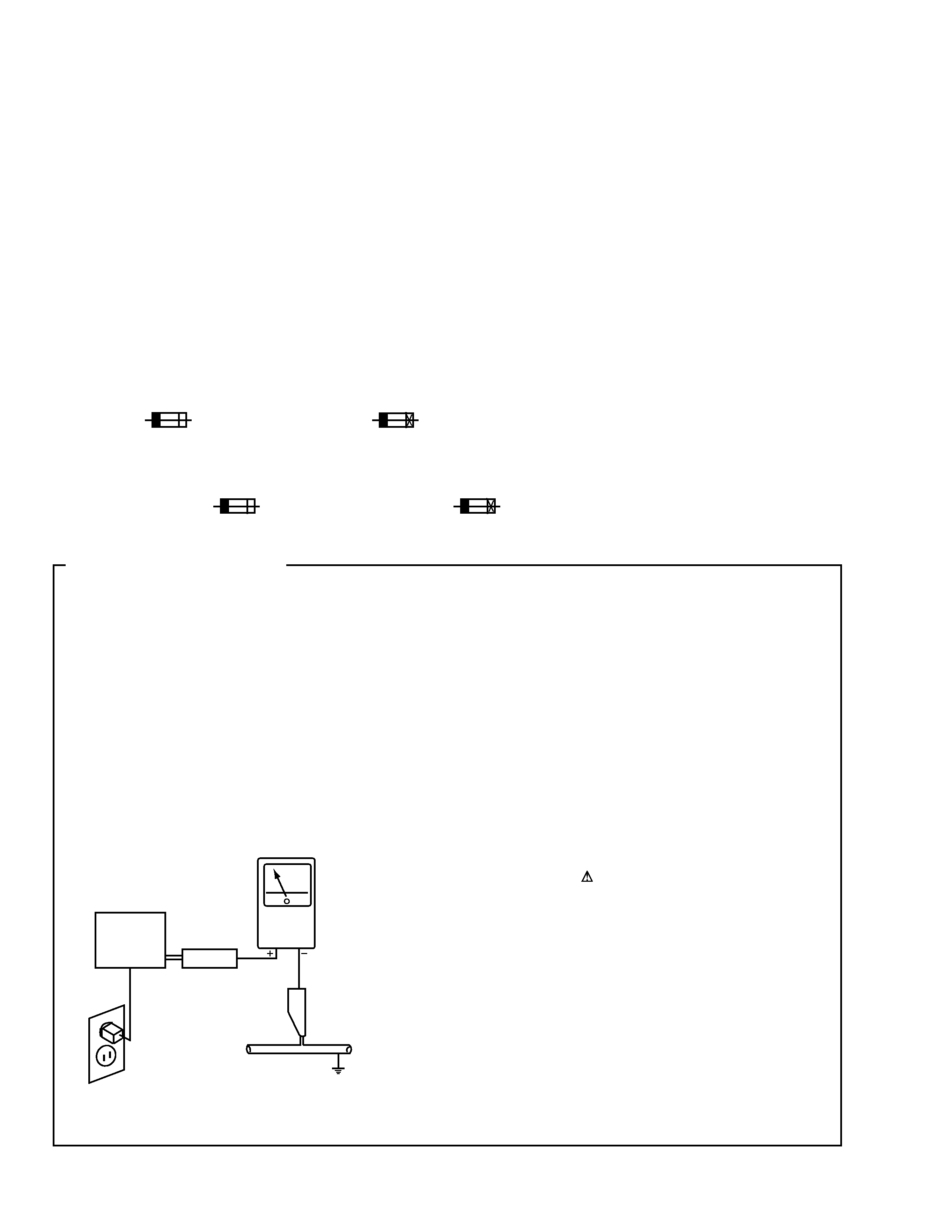
LEAKAGE CURRENT CHECK
Measure leakage current to a known earth ground (water
pipe, conduit, etc.) by connecting a leakage current tester
such as Simpson Model 229-2 or equivalent between the
earth ground and all exposed metal parts of the appliance
(input/output terminals, screwheads, metal overlays, control
shaft, etc.). Plug the AC line cord of the appliance directly
into a 120V AC 60Hz outlet and turn the AC power switch
on. Any current measured must not exceed 0.5mA.
(FOR USA MODEL ONLY)
Leakage
current
tester
Reading should
not be above
0.5mA
Device
under
test
Test all
exposed metal
surfaces
Also test with
plug reversed
(Using AC adapter
plug as required)
Earth
ground
AC Leakage Test
3
PDR-509
IMPORTANT
THIS PIONEER APPARATUS CONTAINS
LASER OF CLASS
b.
SERVICING OPERATION OF THE APPARATUS
SHOULD BE DONE BY A SPECIALLY
INSTRUTED PERSON.
LASER DIODE CHARACTERISTICS
MAXIMUM OUTPUT POWER: 23 mW
WAVELENGTH: 778 787 nm
1. Laser Interlock Mechanism
The position of the switch (S601) on the SERVO
MECHANISM Assy for detecting loading state is detected
by the system microprocessor, and the design prevents
laser diode oscillation when the switch (S601) is not on
CLMP terminal side (CLMP signal is OFF or high level.).
Thus, the interlock will no longer function if the switch
(S601) is deliberately set to CLMP terminal side (low
level).
The interlock also does not function in the test mode
.
Laser diode oscillation will continue, if pin 1 of M51593FP
(IC101) on the PRE-AMP BOARD ASSY mounted on the
CD-R PICKUP is connected to GND, or pin 19 is
connected to low level (ON), or else the terminals of Q101
are shorted to each other (fault condition).
2. When the cover is opened with the servo mechanism
block removed and turned over, close viewing of the
objective lens with the naked eye will cause exposure to a
Class 1 laser beam.
Additional Laser Caution
Refer to page 52.
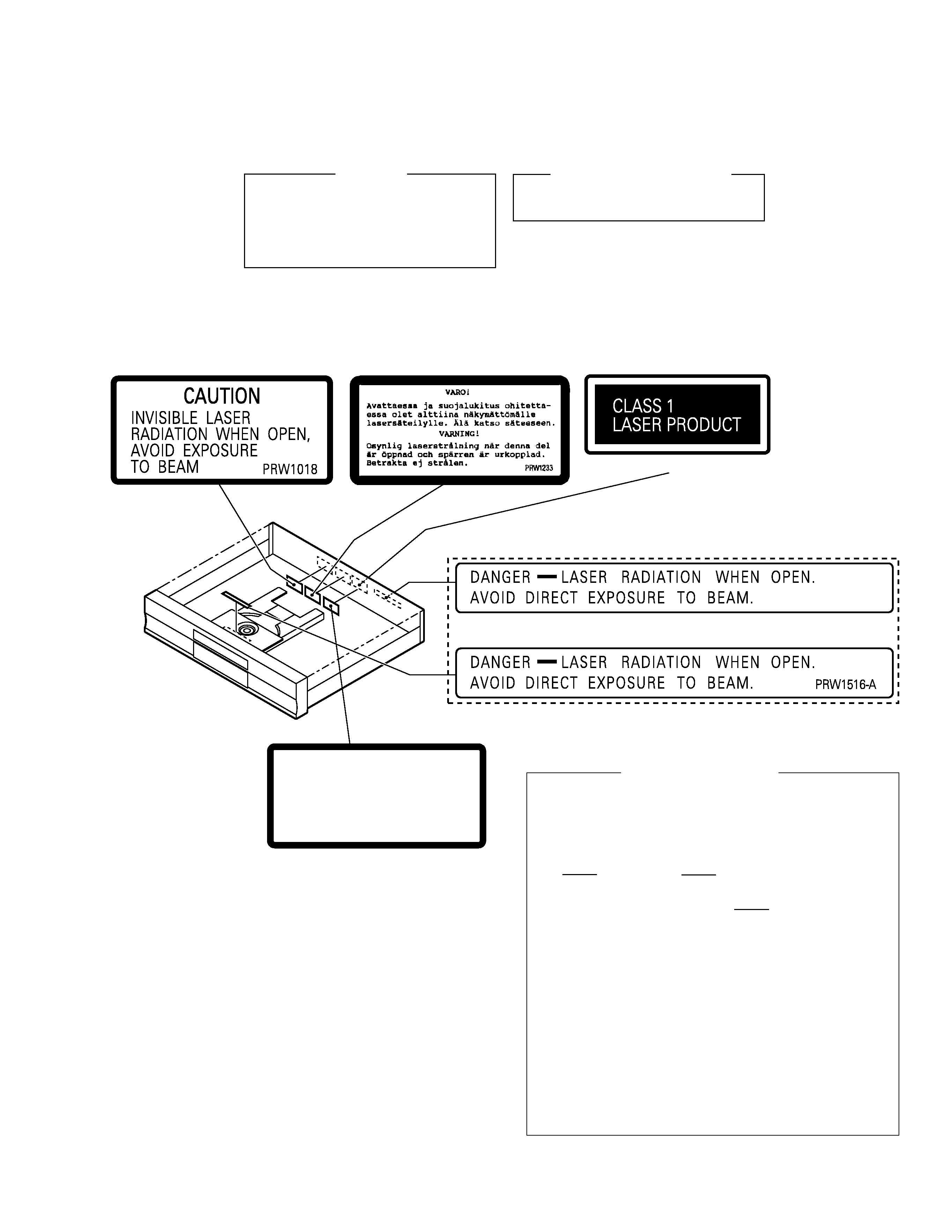
LABEL CHECK
KU/CA Type
Printed on Rear Panel
Printed on Rear Panel
MY and MV Types
MY Type
MY Type
MV Type
USYNLIG LASERSTRÅLING VED ÅBNING NÅR SIKKERHED SAF-
BRYDERE ER UDE AF FUNKTION.
UNDGÅ UDSÆTTELSE FOR STRÅLING
UNSICHTBARE LASER-STRAHLUNG TRITT AUS, WENN DECKEL
(ODER KLAPPE) GEÖFFNET IST! NICHT DEM STRAHL AUSSETZEN!
VRW1094
ADVARSEL
VORSICHT!
4
PDR-509
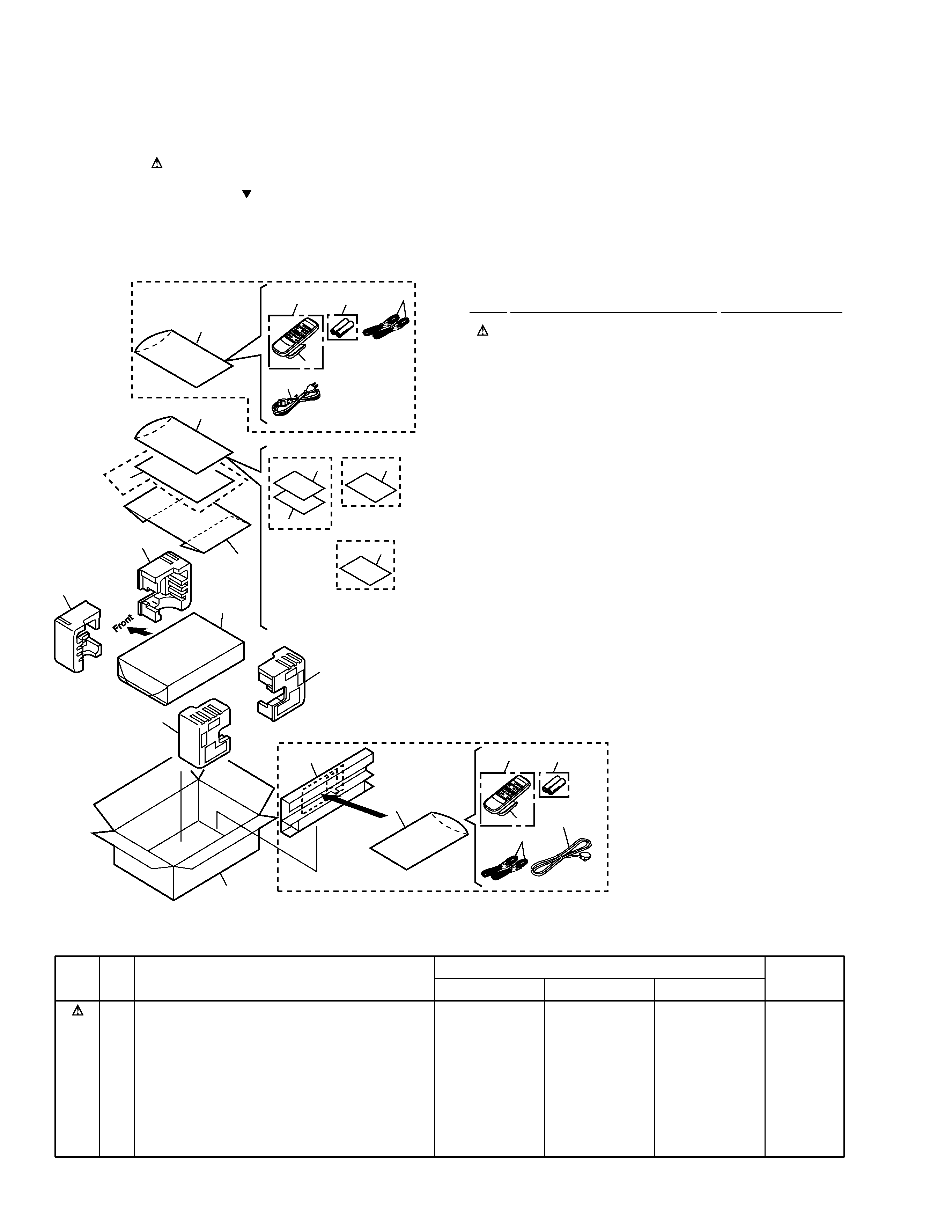
2.1 PACKING
(1) PACKING PARTS LIST
Mark No.
Description
Part No.
2. EXPLODED VIEWS AND PARTS LIST
NOTES:
· Parts marked by "NSP" are generally unavailable because they are not in our Master Spare Parts List.
· The mark found on some component parts indicates the importance of the safety factor of the part.
Therefore, when replacing, be sure to use parts of identical designation.
· Screws adjacent to mark on the product are used for disassembly.
6
5
8
8
8
2
16
12
15
9
10 (2/2)
11 (2/2)
11 (1/2)
7
3
1
4
KU/CA and
MV Types
Only
MY and
MV Types
Only
MY Type
Only
6
5
7
1
3
13
14
2
KU/CA Type
Only
KU/CA and MY Types Only
MV Type Only
10 (1/2)
1
AC Power Cord
See Contrast table (2)
NSP
2
Warranty Card
See Contrast table (2)
3
Audio Cable
PDE1249
4
Operating Instructions (English) See Contrast table (2)
5
Remote Control Unit
PWW1163
(CU-PD114)
6
Battery Cover
RZN1156
NSP
7
Dry Cell Battery (R6P, AA)
VEM-013
8
Polyethylene Bag
Z21-038
(0.03
× 230 × 340)
9
Packing Case
See Contrast table (2)
10
Protector (F)
RHA1238
11
Protector (R)
RHA1239
12
Mirror Mat Sheet
Z23-007
13
Operating Instructions
See Contrast table (2)
(Dutch/Swedish/Spanish/Danish)
14
Operating Instructions
See Contrast table (2)
(English/French/German/Italian)
15
Rear Spacer
See Contrast table (2)
16
Accessory Spacer
PHC1093
Mark No.
Symbol and Description
Part No.
Remarks
KU/CA Type
MY Type
MV Type
NSP
1
2
4
9
13
14
15
AC Power Cord
Warranty Card
Operating Instructions (English)
Packing Case
Operating Instructions
(Dutch/Swedish/Spanish/Danish)
Operating Instructions
(English/French/German/Italian)
Rear Spacer
ADG7021
ARY7023
PRB1296
PHG2382
Not used
Not used
Not used
ADG1127
ARY7022
Not used
PHG2383
PRD1057
PRE1287
Not used
ADG7004
ARY7022
PRB1296
PHG2396
Not used
Not used
RHC1072
(2) CONTRAST TABLE
PDR-509/KU/CA, MY and MV are constructed the same except for the following :
5
PDR-509
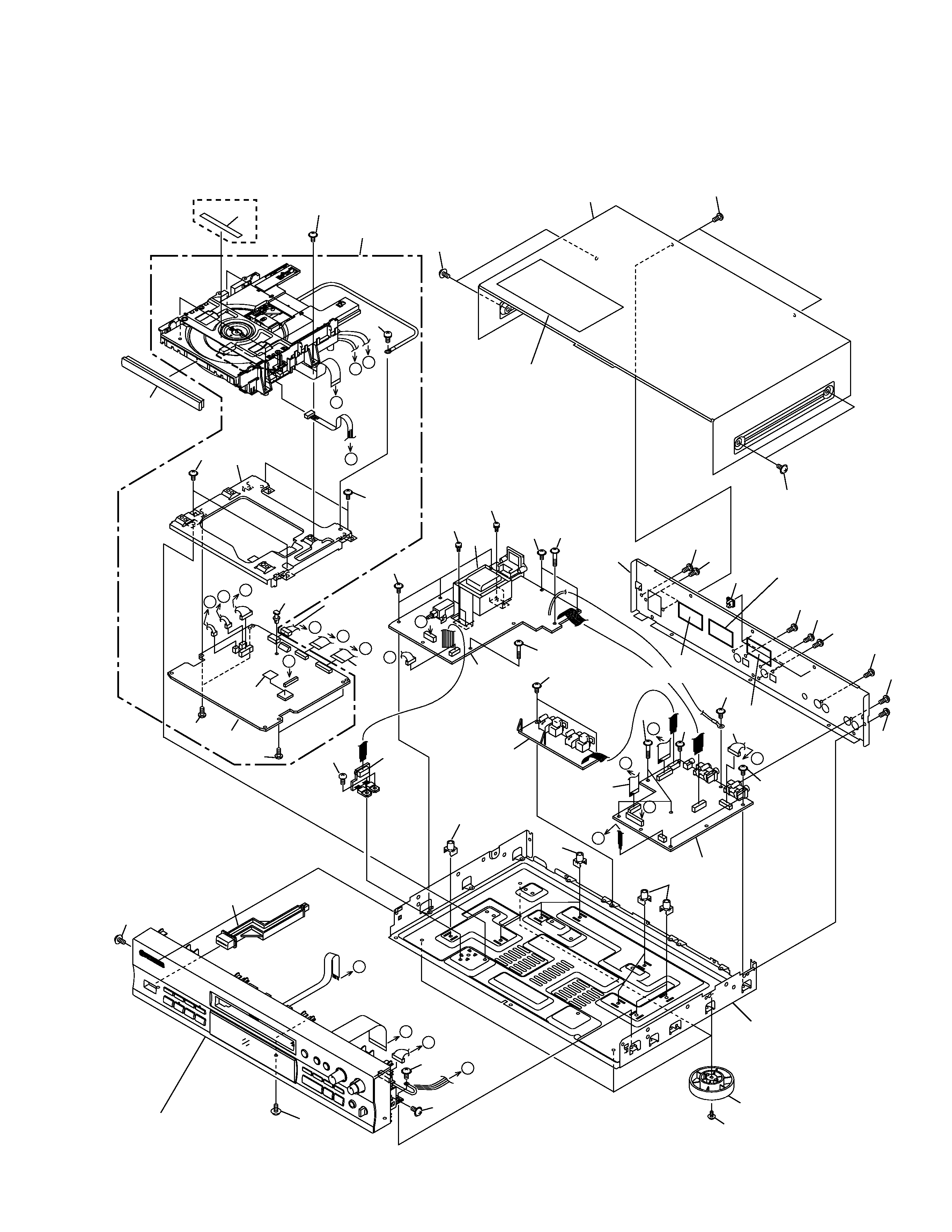
2.2 EXTERIOR SECTION
Refer to
"2.4 CD-R CORE ASSY (1/2)",
"2.5 CD-R CORE ASSY (2/2)".
Refer to
"2.3 FRONT PANEL SECTION".
H
G
E
E
B
K
J
A
D
C
F
G
I
H
B
D
C
A
KU/CA Type Only
KU/CA Type
Only
F
I
J
K
24
24
22
17
15
13
13
13
24
24
20
28
34
6
27
36
19
22
34
34
31
32
1
27
22
22
22
22
22
9
25
25
25
4
3
2
5
22
22
16
14
24
24
24
29
30
22
11
35
24
24
24
18
MY Type
Only
MY Type Only
MV Type Only
22
26
23
23
7
22
34
33
12
10