ORDER NO.
PIONEER CORPORATION 4-1, Meguro 1-chome, Meguro-ku, Tokyo 153-8654, Japan
PIONEER ELECTRONICS SERVICE, INC. P.O. Box 1760, Long Beach, CA 90801-1760, U.S.A.
PIONEER EUROPE NV Haven 1087, Keetberglaan 1, 9120 Melsele, Belgium
PIONEER ELECTRONICS ASIACENTRE PTE. LTD. 253 Alexandra Road, #04-01, Singapore 159936
PIONEER CORPORATION 2000
Remarks
Power Requirement
Type
Model
PDP-V402
PLASMA DISPLAY
ARP3081
TZZA OCT. 2000 Printed in Japan
PDP-V402
LUBW/CA/1
AC120V
THIS MANUAL IS APPLICABLE TO THE FOLLOWING MODEL(S) AND TYPE(S).
In PDP-V402, there are two different models (original model and value analysis model).
Confirm the mark and serial No. of the product rear side, and use each service manual.
SERIAL NO.
Serial No.
Service Manual
1
ARP3081 [This manual]
ARP3034
OTHER
ARP2981 (PDP-V401)
Note: Pages 26 - 77 and 82 - 89 were intentionally left out.
1. SAFETY INFORMATION .................................... 2
2. EXPLODED VIEWS AND PARTS LIST ............. 5
3. BLOCK DIAGRAM AND SCHEMATIC DIAGRAM
....................................................... 16
4. PCB CONNECTION DIAGRAM ....................... 90
5. PCB PARTS LIST ........................................... 133
6. ADJUSTMENT ................................................ 145
CONTENTS:
See note above for pages left out.
7. GENERAL INFORMATION ............................ 152
7.1 DIAGNOSIS .............................................. 152
7.1.1 BURN-IN ......................................... 152
7.1.2 TROUBLESHOOTING ................... 154
7.1.3 DISASSEMBLY .............................. 157
7.1.4 WIRING DIAGRAM ........................ 161
7.2 IC
..................................................... 166
8. PANEL FACILITIES AND SPECIFICATIONS
..................................................... 169
Discrimination Seal
(SILVER)
Serial No.
(
1
)
PRODUCT REAR SIDE

PDP-V402
2
1. SAFETY INFORMATION
This service manual is intended for qualified service technicians; it is not meant for the casual
do-it-yourselfer. Qualified technicians have the necessary test equipment and tools, and have been
trained to properly and safely repair complex products such as those covered by this manual.
Improperly performed repairs can adversely affect the safety and reliability of the product and may
void the warranty. If you are not qualified to perform the repair of this product properly and safely, you
should not risk trying to do so and refer the repair to a qualified service technician.
WARNING
This product contains lead in solder and certain electrical parts contain chemicals which are known to the state of California to
cause cancer, bir th defects or other reproductive harm.
Health & Safety Cod e Section 25249.6 Proposition 65
1.1 SAFETY PRECAUTIONS
NOTICE : Comply with all cautions and safety related notes located
on or inside the cabinet and on the chassis.
The following precautions should be observed :
1. When service is required, even though the PDP UNIT an isolation
transformer should be inserted between the power line and the
set in safety before any service is performed.
2. When replacing a chassis in the set, all the protective devices
must be put back in place, such as barriers, nonmetallic knobs,
adjustment and compartment covershields, isolation resistor-
capacitor, etc.
3. When service is required, observe the original lead dress. Extra
precaution should be taken to assure correct lead dress in the
high voltage circuitry area.
4. Always use the manufacture's replacement components.
Especially critical components as indicated on the circuit diagram
should not be replaced by other manufacture's.
Furthermore where a short circuit has occurred, replace those
components that indicate evidence of overheating.
5. Before returning a serviced set to the customer, the service
technician must thoroughly test the unit to be certain that it is
completely safe to operate without danger of electrical shock,
and be sure that no protective device built into the set by the
manufacture has become defective, or inadvertently defeated
during servicing. Therefore, the following checks should be
performed for the continued protection of the customer and
service technician.
6. Perform the following precautions against unwanted radiation
and rise in internal temperature.
· Always return the internal wiring to the original styling.
· Attach parts (Ground, Rear Cover, Shield Case) surely after
disassembly.
7. Perform the following precautions for the PDP panel.
· When the front case is removed, make sure nothing hits the
panel face, panel corner, and panel edge (so that the glass does
not break).
· Make sure that the panel vent does not break. (Check that the
cover is attached.)
· Handle the FPC connected to the panel carefully.
Twisting or pulling the FPC when connecting it to the connector
will cause it to peel off from the panel.
8. Pay attention to the following.
· Be sure to wire the fan. If the fan does not work, the temperature
will rise and cause the protection circuit to operate.
· When the front case is removed, infrared ray is radiated and
may disturb reception of the remote control unit.
· Pay extreme caution when the front case and rear panel are
removed because this may cause a high risk of disturbance to
TVs and radios in the surrounding.
REMARQUE
(POUR MODÈLE CANADIEN SEULEMENT)
Les symboles de fusible
(fusible de type rapide) et/ou
(fusible de type lent) sur CCI indiquent que les
pièces de remplacement doivent avoir la même désignation.
NOTICE
(FOR CANADIAN MODEL ONLY)
Fuse symbols
(fast operating fuse) and/or
(slow operating fuse) on PCB indicate that replacement parts
must be of identical designation.
PDP-V402
3
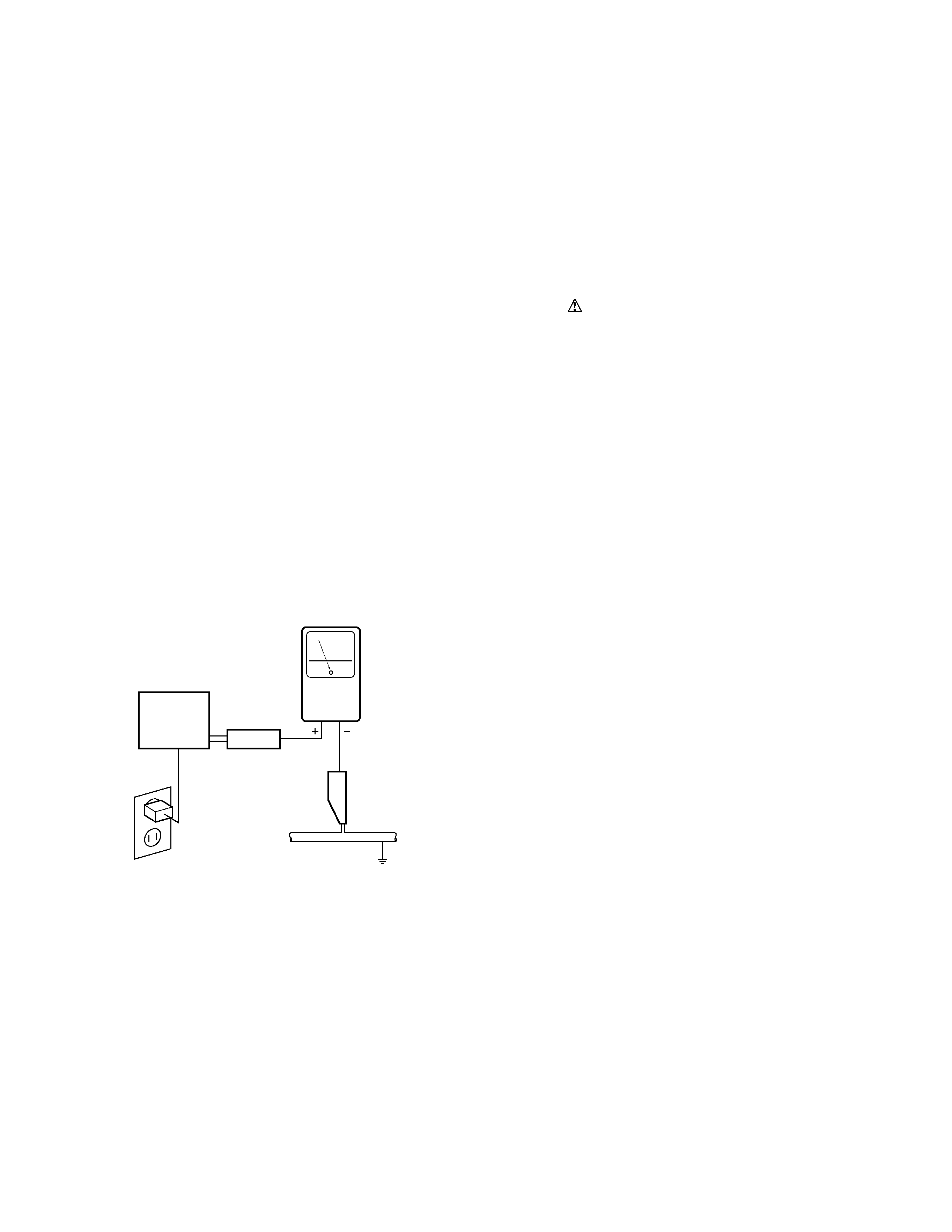
Leakage Current Hot Check
Plug the AC line cord directly into an AC power source (do not use
an isolation transformer for this check).
Turn the AC power switch on.
Using a "Leakage Current Tester (Simpson Model 229 equivalent)",
measure for current from all exposed metal parts of the cabinet
(input/output terminals, screwheads, metal overlays, control shaft,
etc.), particularly any exposed metal part having a return path to the
chassis, to a known earth ground (water pipe, conduit, etc.). Any
current measured must not exceed 0.5mA.
ANY MEASUREMENTS NOT WITHIN THE LIMITS
OUTLINED ABOVE ARE INDICATIVE OF A POTENTIAL
SHOCK HAZARD AND MUST BE CORRECTED BEFORE
RETURNING THE SET TO THE CUSTOMER.
1.2 PRODUCT SAFETY NOTICE
Many electrical and mechanical parts in PIONEER set have special
safety related characteristics. These are often not evident from
visual inspection nor the protection afforded by them necessarily
can be obtained by using replacement components rated for higher
voltage, wattage, etc. Replacement parts which have these special
safety characteristics are identified in this Service Manual.
Electrical components having such features are identified by marking
with a
on the schematics and on the parts list in this Service
Manual.
The use of a substitute replacement component which dose not have
the same safety characteristics as the PIONEER recommended
replacement one, shown in the parts list in this Service Manual, may
create shock, fire or other hazards.
Product Safety is continuously under review and new instructions
are issued from time to time. For the latest information, always
consult the current PIONEER Service Manual. A subscription to, or
additional copies of, PIONEER Service Manual may be obtained at
a nominal charge from PIONEER.
Also test with plug
reversed
(Using AC adapter
plug as required)
Device
under
test
Test all exposed
metal surfaces
Earth ground
Leakage
current
tester
Reading should
not be above
0.5 mA
AC Leakage Test
Leakage Current Cold Check
With the AC plug removed from an AC power source, place a
jumper across the two plug prongs. Turn the AC power switch on.
Using an insulation tester (DC 500V), connect one lead to the
jumpered AC plug and touch the other lead to each exposed metal
part (input/output terminals, screwheads, metal overlays, control
shafts, etc.), particularly any exposed metal part having a return
path to the chassis. Exposed metal parts having a return path to the
chassis should have a minimum resistor reading of 0.3M
and a
maximum resistor reading of 5M
. Any resistor value below or
above this range indicates an abnormality which requires corrective
action. Exposed metal parts not having a return path to the chassis
will indicate an open circuit.
PDP-V402
4
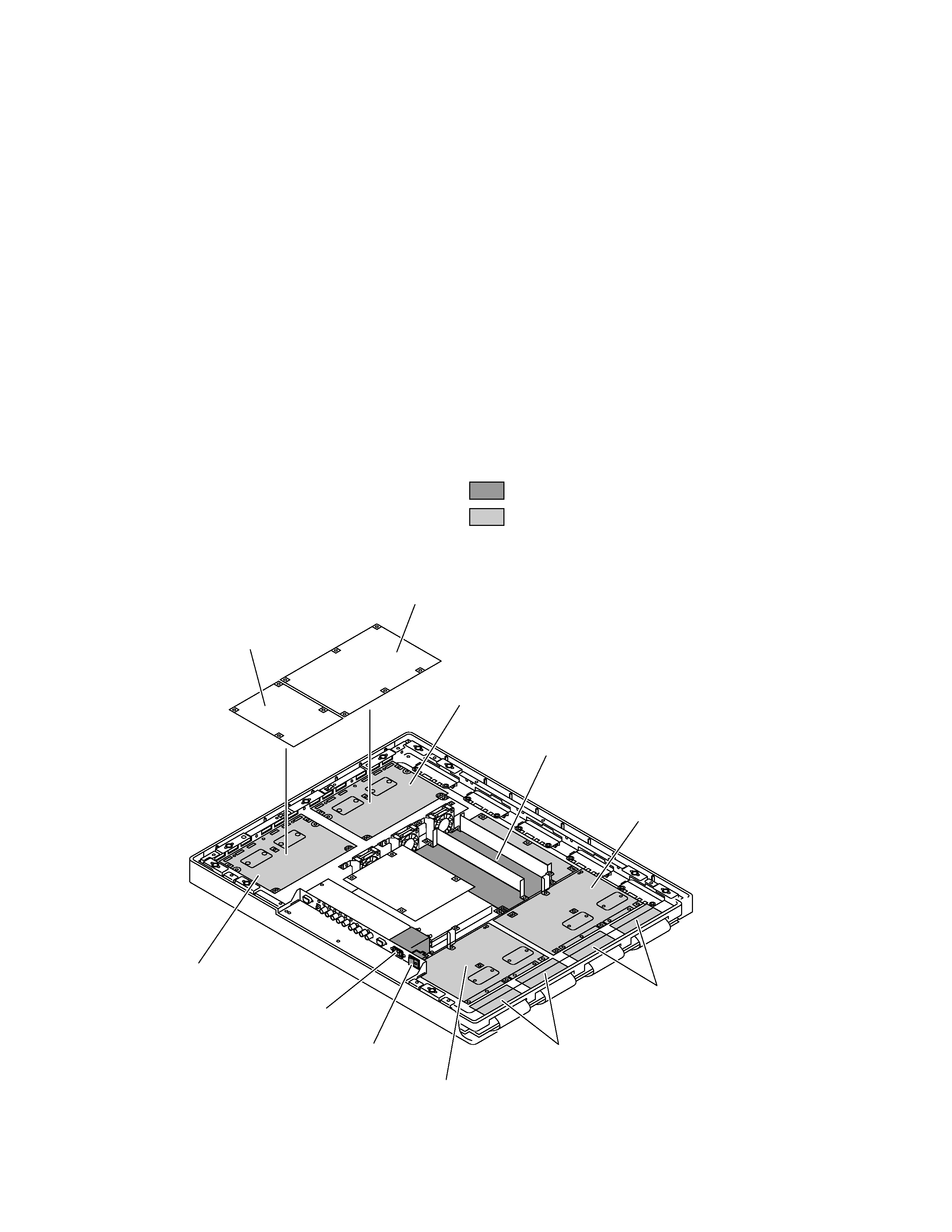
7 Charged Section
The places where the commercial AC power is used without
passing through the power supply transformer.
If the places are touched, there is a risk of electric shock. In addition,
the measuring equipment can be damaged if it is connected to the
GND of the charged section and the GND of the non-charged
section while connecting the set directly to the commercial AC
power supply. Therefore, be sure to connect the set via an insulated
transformer and supply the current.
1.3 CHARGED SECTION AND HIGH VOLTAGE GENERATING POINT
7 Charged Section
(Power supply primary side)
1. AC Power Cord
2. AC Inlet with Filter
3. Power Switch (S1)
4. Fuse (In the MAIN POWER ASSY)
5. STB Transformer and Converter Transformer
(In the MAIN POWER ASSY)
6. Other primary side of the MAIN POWER ASSY
7 High Voltage Generating Point
The places where voltage is 100V or more except for the charged
places described above. If the places are touched, there is a risk of
electric shock.
1. MAIN POWER ASSY ...................................... (170V)
2. X DRIVE (A) ASSY ......................................... (170V)
3. X DRIVE (B) ASSY ......................................... (170V)
4. Y DRIVE (A) ASSY ......................................... (170V)
5. Y DRIVE (B) ASSY ......................................... (170V)
6. SCAN MODULE (A) and (B) .......................... (150V)
For the places, refer to the EXPLODED VIEWS, the SCHEMATIC
DIAGRAM and the PCB CONNECTION DIAGRAM sections.
Part is the high voltage generating points other than the
charged section.
Part is charged section.
Y DRIVE (B) ASSY
SCAN MODULE (A)
SCAN MODULE (B)
Y DRIVE (A) ASSY
X DRIVE (B) ASSY
X DRIVE (A) ASSY
MAIN POWER ASSY
ANALOG VIDEO ASSY
3D Y/C ASSY
Power Switch (S1)
AC Inlet
PDP-V402
5
1
Under Pad A
AHA2249
2
Under Pad B
AHA2250
3
Under Pad C
AHA2251
4
Upper Pad
AHA2252
5
...............................
6
Upper Carton
AHD3052
7
Under Carton
AHD3041
8
Mirror Mat
AHG1273
NSP
9
Literature Bag
AHG-117
10
Operating Instructions
ARD1030
(English/Japanese)
11
Plasma Caution Sheet
ARM1145
12
Plasma Caution Sheet
ARM1147
13
Caution Sheet
ARM1169
14
Remote Control Unit
AXD1441
(CU-V153)
15
Battery Cover
AZN2098
NSP
16
Batteries (R6P, AA)
AEX1025
NSP
17
Vinyl Bag
AHG-064
18
...............................
19
Display Stand V
AMR3232
20
Packing Label
AAX2822
21
AC Power Cord
BDG1025
22
Bolt (Hex)
SMZ80H350FZB
23
Washer
WB80FZB
NSP
24
Warranty Card
ARY1102
NSP
25
Vinyl Pouch
AHG-195
26
...............................
NSP
27
Label
VRW1629
28
Caution Sheet
ARM1176
NSP
29
Warranty Card
ARY1093
30
Discrimination Seal (SILVER)
AAX2817
31
Packing Assy
AHF1001
31
Packing Assy
AHF1001
1
Under Pad A
AHA2249
2
Under Pad B
AHA2250
3
Under Pad C
AHA2251
4
Upper Pad
AHA2252
6
Upper Carton
AHD3052
7
Under Carton
AHD3041
29
25
1
1
2
2
3
7
8
4
9
14
15
19
27
30
20
30
20
27
6
10
11
12
13
24
28
16
17
22
23
9
21
2.1 PACKING
PACKING PARTS LIST
2. EXPLODED VIEWS AND PARTS LIST
NOTES :
Parts marked by " NSP " are generally unavailable because they are not in our Master Spare Parts List.
The
mark found on some component parts indicates the importance of the safety factor of the part.
Therefore, when replacing, be sure to use parts of identical designation.
Screw adjacent to
mark on the product are used for disassembly.
Mark No.
Description
Part No.
Packing Assy (AHF1001) is composed of the following parts.