ORDER NO.
PDP-501MX
PLASMA DISPLAY
ORDER NO.
ARP3011
O- SZS SEP. 1998 Printed in Japan
c
PIONEER ELECTRONIC CORPORATION 4-1, Meguro 1-Chome, Meguro-ku, Tokyo 153-8654, Japan
PIONEER ELECTRONICS SERVICE, INC. P.O. Box 1760, Long Beach, CA 90801-1760, U.S.A.
PIONEER ELECTRONIC (EUROPE) N.V. Haven 1087, Keetberglaan 1, 9120 Melsele, Belgium
PIONEER ELECTRONICS ASIACENTRE PTE. LTD. 501 Orchard Road, #10-00 Wheelock Place, Singapore 238880
PIONEER ELECTRONIC CORPORATION 1998
Type
Model
Power Requirement
Remarks
PDP-501MX
TYVL
AC100-240V
THIS MANUAL IS APPLICABLE TO THE FOLLOWING MODEL(S) AND TYPE(S).
Refer to the service manual ARP2997 for PDP-501MX/KUC.
1. CONTRAST OF MISCELLANEOUS PARTS ........ 2
2. SCHEMATIC DIAGRAM ....................................... 4
3. PCB PARTS LIST ................................................. 6
4. ADJUSTMENT ...................................................... 9
5. GENERAL INFORMATION ................................. 13
5.1 BLOCK DIAGRAM ........................................ 13
CONTENTS
PDP-501MX
2
1. CONTRAST OF MISCELLANEOUS PARTS
CONTRAST OF PDP-501MX/TYVL AND PDP-501MX/KUC
PDP-501MX/TYVL and PDP-501MX/KUC are constructed the same except for the following :
Remarks
Ref. No.
Symbol and Description
Mark
PDP-501MX/TYVL
Part No.
PDP-501MX/KUC
Parts marked by "NSP" are generally unavailable because they are not in our Master Spare Parts List.
The
mark found on some component parts indicates the importance of the safety factor of the part.
Therefore, when replacing, be sure to use parts of identical designation.
NOTES:
When ordering resistors, first convert resistance values into code form as shown in the following examples.
Ex.1 When there are 2 effective digits (any digit apart from 0), such as 560 ohm and 47k ohm (tolerance is shown by J=5%,
and K=10%).
Ex.2 When there are 3 effective digits (such as in high precision metal film resistors).
561
473
R50
1R0
5621
560
47k
0.5
1
RD1/4PU
J
RD1/4PU
J
RN2H
K
RS1P
K
56 x 101
47 x 103
R50
1R0
561
473
5.62k
RN1/4PC
F
562 x 101
5621
¶ Ref. No.: Numbers following P and hyphen () indicate the page(s) and location number(s) in the ARP2997 service manual,
respectively.
PACKING SECTION
P5-7
AC POWER CORD
ADG1178
Not Used
P5-13
UPPER CARTON
AHD2980
AHD2991
P5-15
PLASMA CAUTION SHEET
ARM1145
ARM1149
P5-17
CAUTION SHEET
ARM1146
ARM1154
P5-21
INSTRUCTION MANUAL
ARE1337
ARE1341
(English,French)
INSTRUCTION MANUAL
Not Used
ARC1499
(German,Italian,Dutch,Spain)
P5-25
NSP
WARRANTY CARD
ARY1094
Not Used
EXTERIOR SECTION
P6-1
NSP
REAR CASE
AMR3097
AMR3100
P6-9
NSP
NAME LABEL
AAL2287
AAL2277
P6-10
TERMINAL LABEL L
AAX2662
AAX2680
P6-16
TERMINAL LABEL R
AAX2663
AAX2679
P6-20
BOLT CAUTION LABEL
AAX2656
AAX2681
MANUFACTURED LABEL
AAX-372
Not Used
P6-21
IC PROTECTOR LABEL
AAX2642
Not Used
P6-22
IC PROTECTOR LABEL(F)
AAX2675
Not Used
SOLDER WARNING LABEL
AAX2644
Not Used
UPC CODE LABEL
AAX2673
Not Used
NSP
EARTH LABEL
Not Used
BAX1014
P7-25
AC INLET WITH FILTER
AKP1190
AKP1192
P7-38
CONTROL NAME PLATE
AAK2719
AAK2720
NSP
SERIAL SHEET
Not Used
AAX2609
P8-3
FRONT CASE
AMB2632
AMB2624
P11-35
NSP
3D Y/C HOLDER
ANG2293
Not Used
TERMINAL COVER(232C)
ANG2294
Not Used
TERMINAL COVER
AMR3099
Not Used
SCREW GUARD
Not Used
AMR3114
SCREW GUARD B
Not Used
AMR3138
PCB SECTION
NSP
ANALOG VIDEO ASSY
AWV1685
AWV1691
VIDEO ASSY
AWZ6305
AWZ6331
3 LINE Y/C ASSY
Not Used
AWZ6306
3D Y/C SEP. ASSY
AWV1709
Not Used
3D Y/C SEP. ASSY
AWZ6332
SIDE SWITCH ASSY
AWZ6315
SIDE SWITCH ASSY
Not Used
AWV1727
SIDE SWITCH ASSY
AWZ6315
POWER SUPPLY MODULE
AXY1029
AXY1044
*6 AXY1044 have no
service part.
*6
*4 Refer to page 6 and 13.
*4
*1 Refer to page 3.
*3
*3
*1
*2 Refer to page 3.
*2
*3 Refer to page 3.
*5
*5 Refer to page 6,12 and 14.
PDP-501MX
3
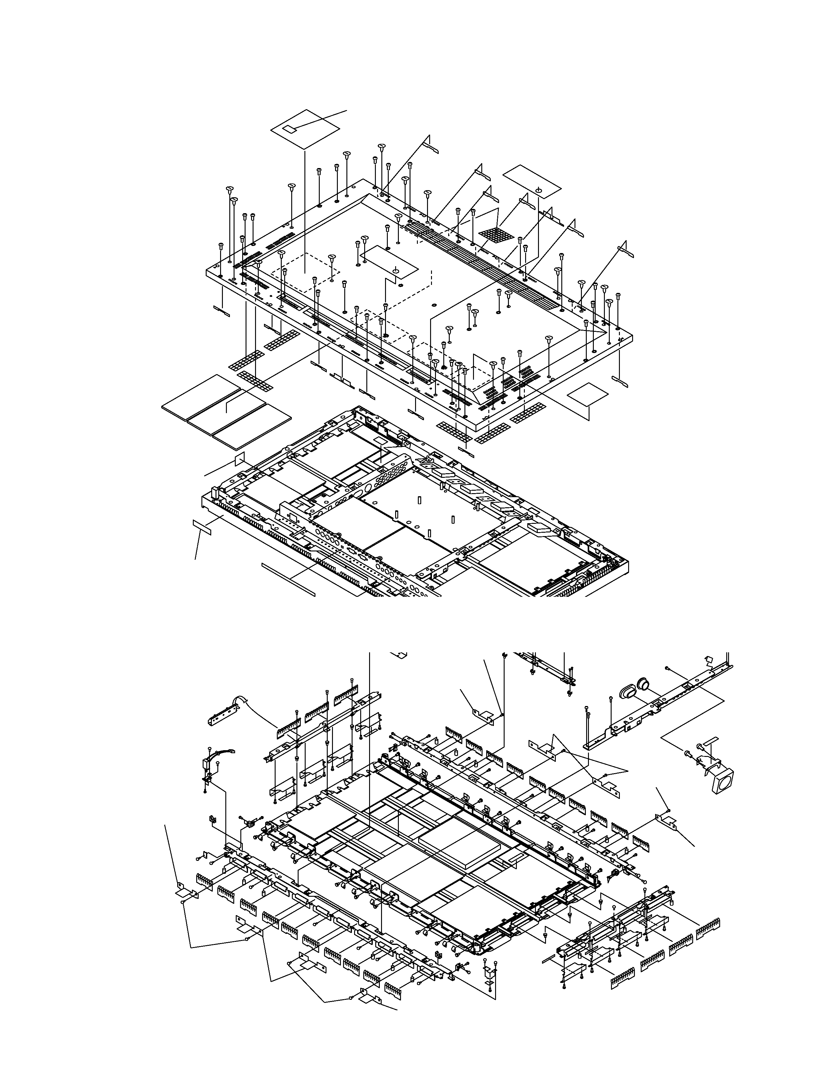
· EXPLODED VIEWS
REAR CASE
Screw guard
AMR3114
Screw guard
AMR3114
Screw guard B
AMR3138
Screw
BMB30P140FZK
BMB30P140FZK
Screw guard
AMR3114
Screw guard B
AMR3138
Screw guard
AMR3114
Screw
BMB30P140FZK
Screw
BMB30P140FZK
Serial sheet
AAX2609
Earth label
BAX1014
Serial sheet (Pasting position is changed from the KUC model.)
AAX1322
MAIN SECTION (1)
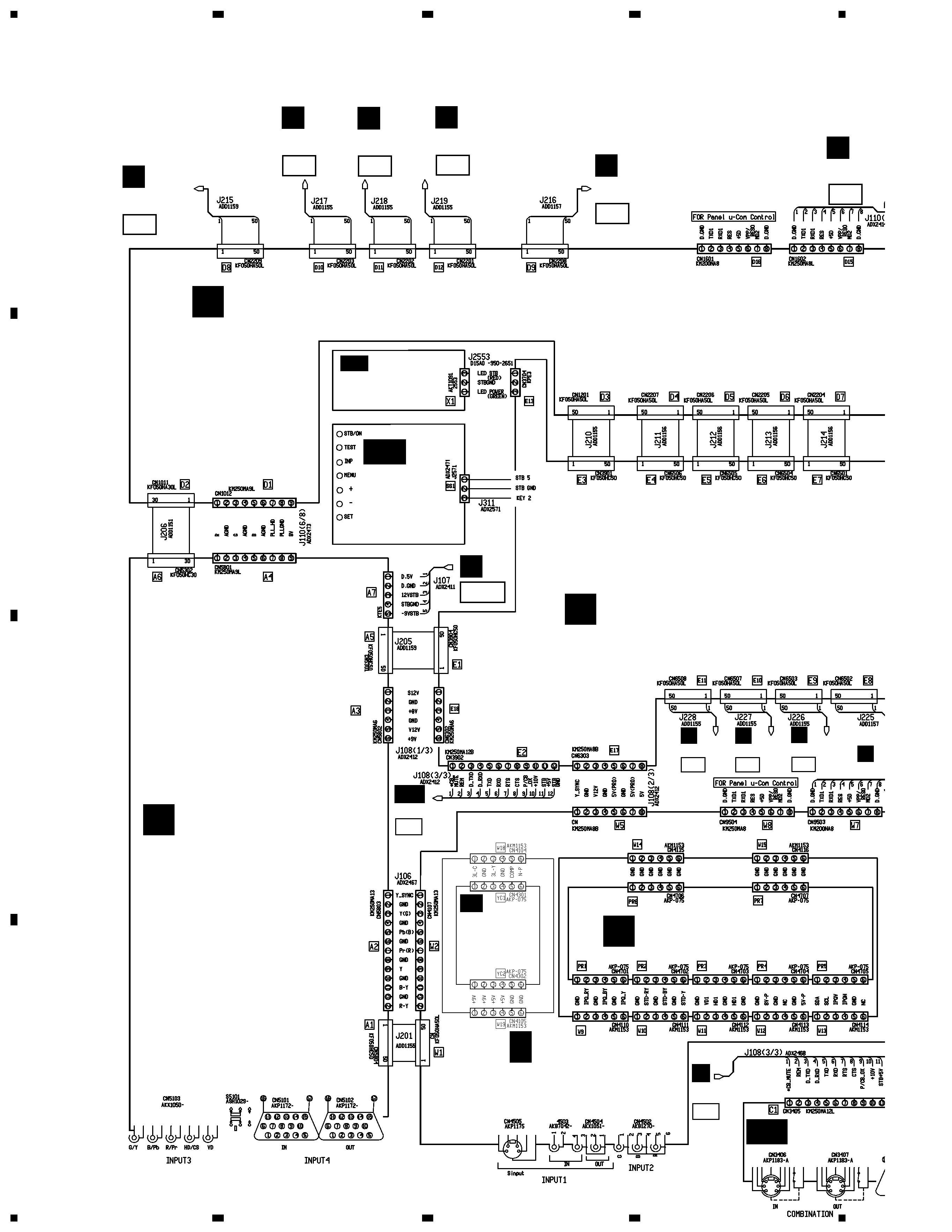
PDP-501MX
4
A
B
C
D
1
23
4
12
3
4
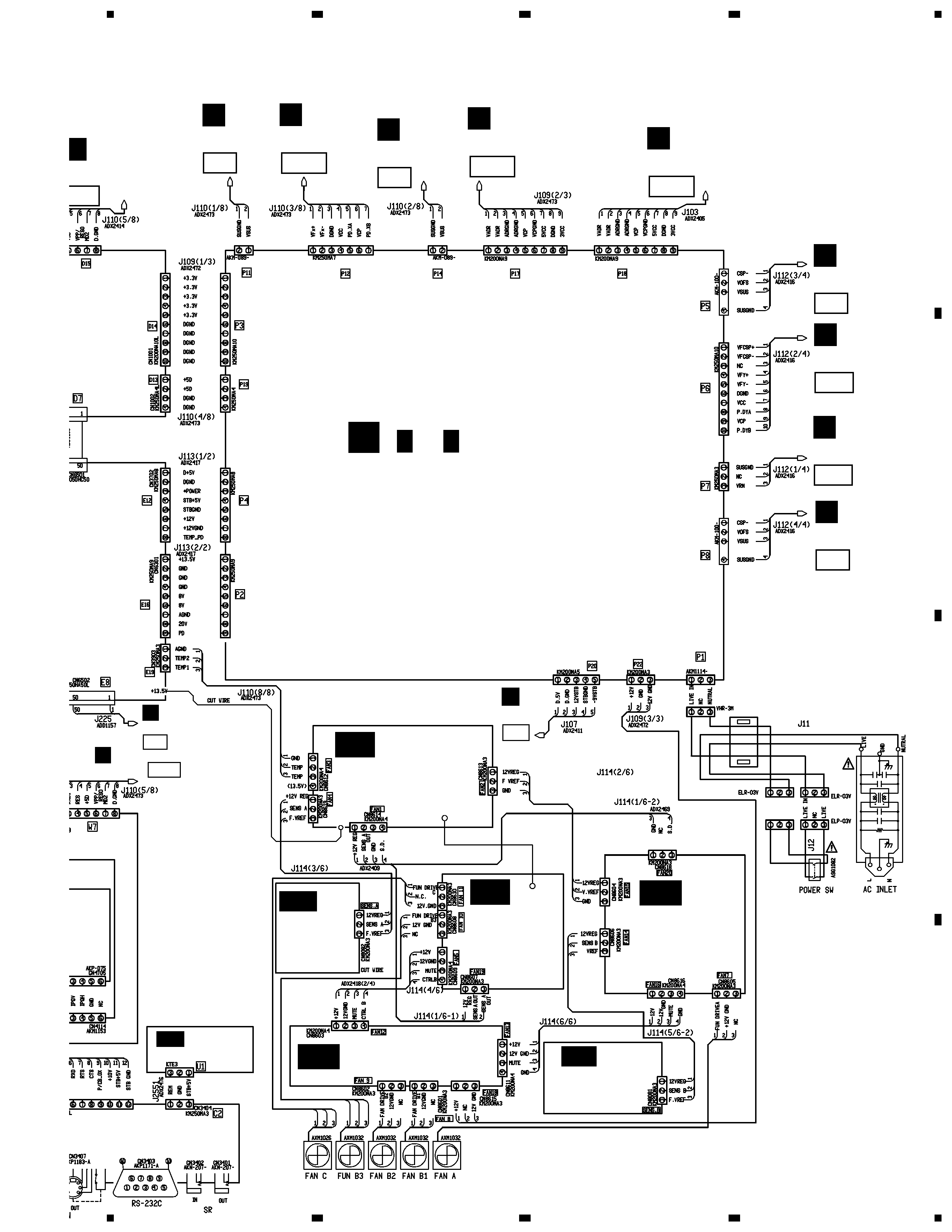
2. SCHEMATIC DIAGRAM
2.1 OVERALL CONNECTION DIAGRAM (1/2)
J5101
9502
JA
9501
E
CN2604
F1
L
CN7103
T1
L
CN7102
T2
L
CN7101
T3
G
CN3104
H1
A
CN410
B7
DIGITAL VIDEO ASSY (AWV1728)
D
INDICATOR
ASSY
(AWZ6225)
I
AH
P20
J
PROGESSIVE BLOCK
(AWZ6222)
B
N
CN7303
K1
N
CN7302
K2
N
CN7301
K3
D
CN1
RGB ASSY (AWV1687)
VIDEO ASSY
(AWZ6331)
CONTROL
(AWZ6307)
AO
SIDE
SWITCH
ASSY
(AWZ6315)
AQ
I
CN3902
E2
CN3405
C1
AO
U-CON ASSY (AWV1689)
C
3 LINE
Y/C ASSY
(AWZ6306)
F
AR
F
A
PDP-501MX
5
A
B
C
D
5
67
8
5
6
7
8
Note : When ordering service parts, be sure to refer to "EXPLODED
VIEWS and PARTS LIST" or "PCB PARTS LIST"
AKC1002
K8601
K8602
AKC1002
Y312
YJ5HA0-20-5/5
J311
ADX2475
NUTRAL
IN
NC
NUTRAL
ELP-03V
ADX2503
ADX2502
ATX1031
AKP1192
A
CN4101
B7
G
CN3101
H8
G
CN3102
H11
H
CN3101
I 8
G
CN3201
H10
F10
E
CN2601
F9
E
CN2602
T15
L
CN7111
K15
N
CN7311
F
CN2601
G8
J
POWER SUPPLY MODULE
(AXY1044)
2/2
J
(
)
1/2 ,
J
K
01
H
CN3104
I 1
D15
D
CN1602
IR RECEIVE
ASSY
(AWZ6224)
AG
NTROL ASSY
Z6307)
DC FAN A ASSY
(AWZ6323)
A I
DC FAN B
ASSY
(AWZ6324)
AJ
DC FAN C ASSY
(AWZ6325)
AK
DC FAN D
ASSY
(AWZ6326)
AL
SENSOR A
ASSY
(AWZ6309)
AM
SENSOR B
ASSY
(AWZ6310)
AN
J5101
A7
C