ORDER NO.
PIONEER CORPORATION 4-1, Meguro 1-chome, Meguro-ku, Tokyo 153-8654, Japan
PIONEER ELECTRONICS (USA) INC. P.O. Box 1760, Long Beach, CA 90801-1760, U.S.A.
PIONEER EUROPE NV Haven 1087, Keetberglaan 1, 9120 Melsele, Belgium
PIONEER ELECTRONICS ASIACENTRE PTE. LTD. 253 Alexandra Road, #04-01, Singapore 159936
PIONEER CORPORATION 2007
PDP-5010FD
ARP3455
PLASMA DISPLAY SYSTEM
PDP-5010FD
THIS MANUAL IS APPLICABLE TO THE FOLLOWING MODEL(S) AND TYPE(S).
Model
Type
Power Requirement
Remarks
PDP-5010FD
KUCXC
AC 120 V
PDP-5010FD
KUC
AC 120 V
For details, refer to "Important Check Points for good servicing".
T-IZS-002 JULY 2007 Printed in Japan

PDP-5010FD
2
1
2
3
4
1
234
C
D
F
A
B
E
SAFETY INFORMATION
This service manual is intended for qualified service technicians ; it is not meant for the casual
do-it-yourselfer. Qualified technicians have the necessary test equipment and tools, and have been
trained to properly and safely repair complex products such as those covered by this manual.
Improperly performed repairs can adversely affect the safety and reliability of the product and may
void the warranty. If you are not qualified to perform the repair of this product properly and safely,
you should not risk trying to do so and refer the repair to a qualified service technician.
WARNING
This product contains lead in solder and certain electrical parts contain chemicals which are known to the state of California to
cause cancer, birth defects or other reproductive harm.
Health & Safety Code Section 25249.6 - Proposition 65
NOTICE
(FOR CANADIAN MODEL ONLY)
Fuse symbols
(fast operating fuse) and/or
(slow operating fuse) on PCB indicate that replacement parts must
be of identical designation.
REMARQUE
(POUR MODÈLE CANADIEN SEULEMENT)
Les symboles de fusible
(fusible de type rapide) et/ou
(fusible de type lent) sur CCI indiquent que les pièces
de remplacement doivent avoir la même désignation.
SAFETY PRECAUTIONS
NOTICE : Comply with all cautions and safety related notes
located on or inside the cabinet and on the chassis.
The following precautions should be observed :
1. When service is required, even though the PDP UNIT an
isolation transformer should be inserted between the power line
and the set in safety before any service is performed.
2. When replacing a chassis in the set, all the protective devices
must be put back in place, such as barriers, nonmetallic knobs,
adjustment and compartment covershields, isolation resistor-
capacitor, etc.
3. When service is required, observe the original lead dress. Extra
precaution should be taken to assure correct lead dress in the
high voltage circuitry area.
4. Always use the manufacture's replacement components.
Especially critical components as indicated on the circuit
diagram should not be replaced by other manufacture's.
Furthermore where a short circuit has occurred, replace those
components that indicate evidence of overheating.
5. Before returning a serviced set to the customer, the service
technician must thoroughly test the unit to be certain that it is
completely safe to operate without danger of electrical shock,
and be sure that no protective device built into the set by the
manufacture has become defective, or inadvertently defeated
during servicing. Therefore, the following checks should be
performed for the continued protection of the customer and
servicetechnician.
6. Perform the following precautions against unwanted radiation
and rise in internal temperature.
· Always return the internal wiring to the original styling.
· Attach parts (Gascket, Ferrite Core, Ground, Rear Cover,
Shield Case etc.) surely after disassembly.
7. Perform the following precautions for the PDP panel.
· When the front case is removed, make sure nothing hits the
panel face, panel corner, and panel edge (so that the glass does
not break).
· Make sure that the panel vent does not break. (Check that the
cover is attached.)
· Handle the FPC connected to the panel carefully.
Twisting or pulling the FPC when connecting it to the
connector will cause it to peel off from the panel.
8. Pay attention to the following.
· Pay extreme caution when the front case and rear panel are
removed because this may cause a high risk of disturbance to
TVs and radios in the surrounding.
PDP-5010FD
3
5
6
7
8
56
7
8
C
D
F
A
B
E
Leakage Current Cold Check
With the AC plug removed from an AC power source, place a
jumper across the two plug prongs. Turn the AC power switch on.
Using an insulation tester (DC 500V), connect one lead to the
jumpered AC plug and touch the other lead to each exposed metal
part (input/output terminals, screwheads, metal overlays, control
shafts, etc.), particularly any exposed metal part having a return
path to the chassis. Exposed metal parts having a return path to
the chassis should have a minimum resistor reading of 4 M
.
The below 4 M
resistor value indicate an abnormality which
require corrective action. Exposed metal parts not having a return
path to the chassis will indicate an open circuit.
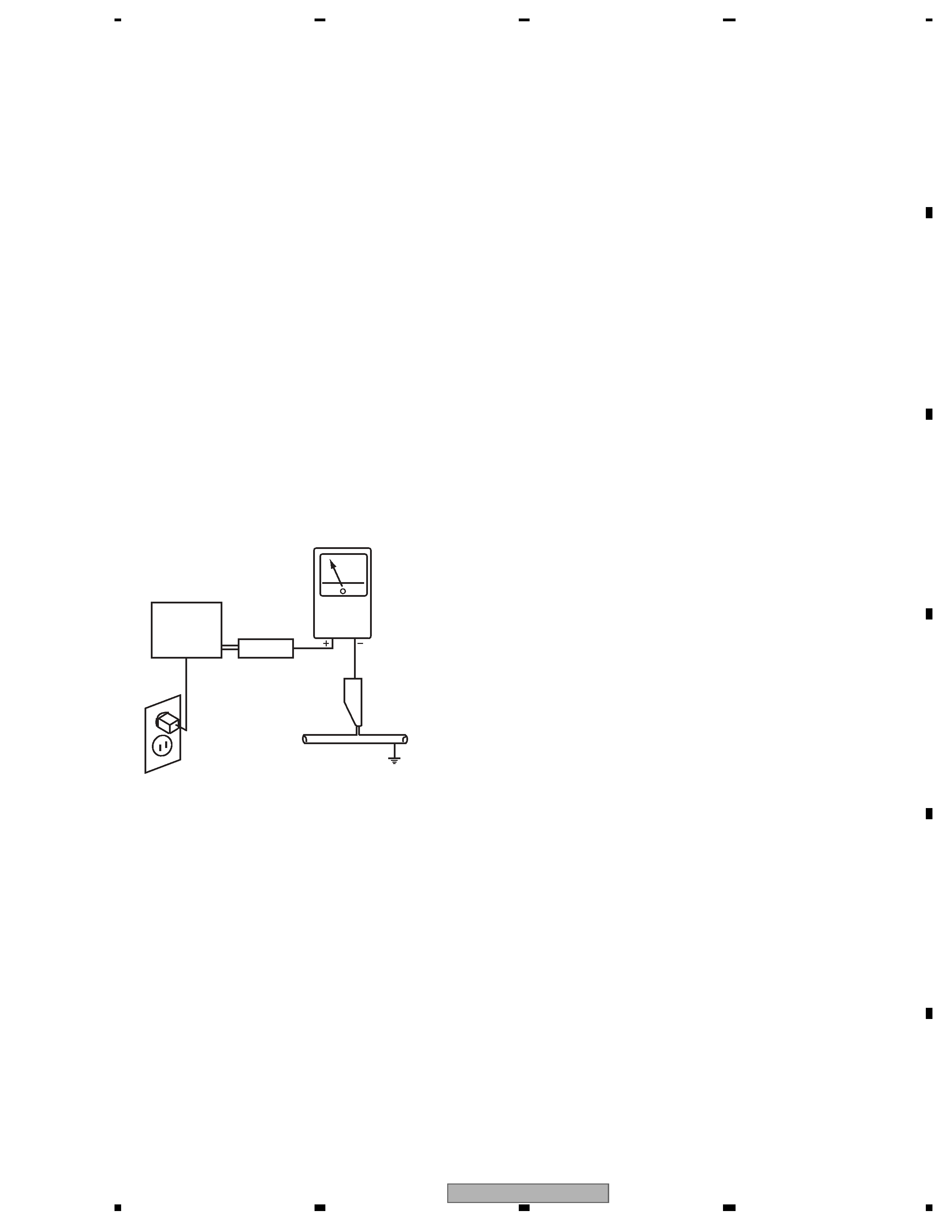
Leakage Current Hot Check
Plug the AC line cord directly into an AC power source (do not
use an isolation transformer for this check).
Turn the AC power switch on.
Using a "Leakage Current Tester (Simpson Model 229
equivalent)", measure for current from all exposed metal parts of
the cabinet (input/output terminals, screwheads, metal overlays,
control shaft, etc.), particularly any exposed metal part having a
return path to the chassis, to a known earth ground (water pipe,
conduit, etc.). Any current measured must not exceed 1 mA.
ANY MEASUREMENTS NO T WITHIN THE LIMITS
OUTLINED ABOVE ARE INDICATIVE OF A POTENTIAL
SHOCK HAZARD AND MUST BE CORRECTED BEFORE
RETURNING THE SET TO THE CUSTOMER.
PRODUCT SAFETY NOTICE
Many electrical and mechanical parts in PIONEER set have
special safety related characteristics. These are often not evident
from visual inspection nor the protection afforded by them
necessarily can be obtained by using replacement components
rated for higher voltage, wattage, etc. Replacement parts which
have these special safety characteristics are identified in this
Service Manual.
Electrical components having such features are identified by
marking with a
> on the schematics and on the parts list in this
Service Manual.
The use of a substitute replacement component which dose not
ha v e the same safety characteristics as the PIONEER
recommended replacement one, shown in the parts list in this
Service Manual, may create shock, fire or other hazards.
Product Safety is continuously under review and new instructions
are issued from time to time. For the latest information, always
consult the current PIONEER Service Manual. A subscription to,
or additional copies of, PIONEER Service Manual may be
obtained at a nominal charge from PIONEER.
Leakage
current
tester
Reading should
not be above
1 mA
Device
under
test
Test all
exposed metal
surfaces
Also test with
plug reversed
(Using AC adapter
plug as required)
Earth
ground
AC Leakage Test
PDP-5010FD
4
1
2
3
4
1
234
C
D
F
A
B
E
[Important Check Points for Good Servicing]
In this manual, procedures that must be performed during repairs are marked with the below symbol.
Please be sure to confirm and follow these procedures.
1. Product safety
Please conform to product regulations (such as safety and radiation regulations), and maintain a safe servicing environment by
following the safety instructions described in this manual.
1 Use specified parts for repair.
Use genuine parts. Be sure to use important parts for safety.
2 Do not perform modifications without proper instructions.
Please follow the specified safety methods when modification(addition/change of parts) is required due to interferences such as
radio/TV interference and foreign noise.
3 Make sure the soldering of repaired locations is properly performed.
When you solder while repairing, please be sure that there are no cold solder and other debris.
Soldering should be finished with the proper quantity. (Refer to the example)
4 Make sure the screws are tightly fastened.
Please be sure that all screws are fastened, and that there are no loose screws.
5 Make sure each connectors are correctly inserted.
Please be sure that all connectors are inserted, and that there are no imperfect insertion.
6 Make sure the wiring cables are set to their original state.
Please replace the wiring and cables to the original state after repairs.
In addition, be sure that there are no pinched wires, etc.
7 Make sure screws and soldering scraps do not remain inside the product.
Please check that neither solder debris nor screws remain inside the product.
8 There should be no semi-broken wires, scratches, melting, etc.on the coating of the power cord.
Damaged power cords may lead to fire accidents, so please be sure that there are no damages.
If you find a damaged power cord, please exchange it with a suitable one.
9 There should be no spark traces or similar marks on the power plug.
When spark traces or similar marks are found on the power supply plug, please check the connection and advise on secure
connections and suitable usage. Please exchange the power cord if necessary.
a Safe environment should be secured during servicing.
When you perform repairs, please pay attention to static electricity, furniture, household articles, etc. in order to prevent injuries.
Please pay attention to your surroundings and repair safely.
2. Adjustments
To keep the original performance of the products, optimum adjustments and confirmation of characteristics within specification.
Adjustments should be performed in accordance with the procedures/instructions described in this manual.
4. Cleaning
For parts that require cleaning, such as optical pickups, tape deck heads, lenses and mirrors used in projection monitors, proper
cleaning should be performed to restore their performances.
3. Lubricants, Glues, and Replacement parts
Use grease and adhesives that are equal to the specified substance.
Make sure the proper amount is applied.
5. Shipping mode and Shipping screws
To protect products from damages or failures during transit, the shipping mode should be set or the shipping screws should be
installed before shipment. Please be sure to follow this method especially if it is specified in this manual.

PDP-5010FD
5
5
6
7
8
56
7
8
C
D
F
A
B
E
CONTENTS
SAFETY INFORMATION ......................................................................................................................................................... 2
1. SERVICE PRECAUTIONS.................................................................................................................................................... 7
1.1 NOTES ON SOLDERING ............................................................................................................................................... 7
1.2 CHARGED SECTION AND HIGH VOLTAGE GENERATING POINT ............................................................................. 8
2. SPECIFICATIONS................................................................................................................................................................. 9
2.1 ACCESSORIES .............................................................................................................................................................. 9
2.2 SPECIFICATIONS ........................................................................................................................................................ 10
2.3 PANEL FACILITIES....................................................................................................................................................... 11
3. BASIC ITEMS FOR SERVICE ............................................................................................................................................ 14
3.1 CHECK POINTS AFTER SERVICING ......................................................................................................................... 14
3.2 QUICK REFERENCE ................................................................................................................................................... 15
3.3 PCB LOCATION ........................................................................................................................................................... 17
3.4 JIGS LIST ..................................................................................................................................................................... 18
3.5 CLEANING ................................................................................................................................................................... 18
4. BLOCK DIAGRAM .............................................................................................................................................................. 20
4.1 OVERALL WIRING DIAGRAM (1/2) ............................................................................................................................. 20
4.2 OVERALL WIRING DIAGRAM (2/2) ............................................................................................................................. 22
4.3 OVERALL BLOCK DIAGRAM (1/2) .............................................................................................................................. 24
4.4 OVERALL BLOCK DIAGRAM (2/2) .............................................................................................................................. 26
4.5 POWER SUPPLY UNIT ................................................................................................................................................ 28
4.6 50F X DRIVE ASSY...................................................................................................................................................... 29
4.7 50F Y DRIVE, 50F SCAN A, B, C and D ASSYS ......................................................................................................... 30
4.8 POWER SUPPLY BLOCK of 50F X, Y DRIVE and 50F SCAN A, B, C and D ASSYS ................................................ 31
4.9 50F ADDRESS L and S ASSYS................................................................................................................................... 32
4.10 50F DIGITAL ASSY .................................................................................................................................................... 33
4.11 MAIN ASSY (DTV BLOCK DIAGRAM)....................................................................................................................... 34
4.12 POWER SUPPLY BLOCK of MAIN ASSY.................................................................................................................. 36
4.13 TANSHI ASSY ............................................................................................................................................................ 38
4.14 50FHD LED and FHD IR ASSYS ............................................................................................................................... 39
4.15 POWER SUPPLY BLOCK of FHD RLS and SIDE KEY ASSYS ................................................................................ 40
5. DIAGNOSIS ........................................................................................................................................................................ 41
5.1 POWER SUPPLY OPERATION.................................................................................................................................... 41
5.1.1 LED DISPLAY INFORMATION............................................................................................................................... 41
5.1.2 POWER ON SEQUENCE ...................................................................................................................................... 42
5.1.3 DETAILS OF POWER ON SEQUENCE................................................................................................................. 43
5.2 DIAGNOSIS FLOWCHART OF FAILURE ANALYSIS .................................................................................................. 45
5.2.1 WHOLE UNIT......................................................................................................................................................... 45
5.2.2 POWER SUPPLY UNIT.......................................................................................................................................... 47
5.2.3 DRIVE ASSY.......................................................................................................................................................... 48
5.2.4 DIGITAL ASSY ....................................................................................................................................................... 52
5.2.5 MAIN ASSY............................................................................................................................................................ 53
5.2.6 VIDEO SYSTEM .................................................................................................................................................... 54
5.2.7 AUDIO SYSTEM .................................................................................................................................................... 60
5.3 DIAGNOSIS OF PD (POWER-DOWN) ........................................................................................................................ 63
5.3.1 BLOCK DIAGRAM OF THE POWER-DOWN SIGNAL .......................................................................................... 63
5.3.2 PD (POWER-DOWN) DIAGNOSIS OF FAILURE ANALYSIS ................................................................................ 64
5.4 DIAGNOSIS OF SD (SHUTDOWN) ............................................................................................................................. 67
5.4.1 BLOCK DIAGRAM OF THE SHUTDOWN SIGNAL ............................................................................................... 67
5.4.2 SD (SHUTDOWN) DIAGNOSIS ............................................................................................................................. 68
5.5 NON-FAILURE INFORMATION .................................................................................................................................... 70
5.5.1 INFORMATION ON SYMPTOMS THAT DO NOT CONSTITUTE FAILURE .......................................................... 70
5.5.2 FUNCTION OF DECREASING THE BRIGHTNESS LEVEL ................................................................................. 73
5.6 OUTLINE OF THE OPERATION .................................................................................................................................. 74
5.6.1 PANEL DRIVE-POWER ON / OFF FUNCTION ..................................................................................................... 74
5.6.2 SPECIFICATION OF THE FAN CONTROL............................................................................................................ 75
5.6.3 PROCESSING IN ABNORMALITY ........................................................................................................................ 76
5.6.4 TRAP SWITCH....................................................................................................................................................... 79