ORDER NO.
PIONEER CORPORATION 4-1, Meguro 1-chome, Meguro-ku, Tokyo 153-8654, Japan
PIONEER ELECTRONICS (USA) INC. P.O. Box 1760, Long Beach, CA 90801-1760, U.S.A.
PIONEER EUROPE NV Haven 1087, Keetberglaan 1, 9120 Melsele, Belgium
PIONEER ELECTRONICS ASIACENTRE PTE. LTD. 253 Alexandra Road, #04-01, Singapore 159936
PIONEER CORPORATION 2004
RRV2905
MULTI COMPACT DISC PLAYER
PD-M427
RFXJ
T ZZR MAR. 2004 Printed in Japan
PD-M427
For details, refer to "Important symbols for good services" .
'
7
6
6
MULTI COMPACT DISC PLAYER
STANDBY/ON
DISC
TRACK
MIN
SEC
1-BIT·DLC DIRECT LINEAR CONVERSION
EJECT
REPEAT PROGRAM
DISC
TRACK/MANUAL
RANDOM
HILITE
STOP PLAY/PAUSE
-DISC
MULTI CD
0
41
¢
¡
Type
Model
Power Requirement
The voltage can be converted by the following method.
PD-M427
RFXJ
AC110-127V/ 220-240V
THIS MANUAL IS APPLICABLE TO THE FOLLOWING MODEL(S) AND TYPE(S).
With the voltage selector
2
1
23
4
12
3
4
C
D
F
A
B
E
PD-M427
SAFETY INFORMATION
This service manual is intended for qualified service technicians ; it is not meant for the casual do-
it-yourselfer. Qualified technicians have the necessary test equipment and tools, and have been
trained to properly and safely repair complex products such as those covered by this manual.
Improperly performed repairs can adversely affect the safety and reliability of the product and
may void the warranty. If you are not qualified to perform the repair of this product properly and
safely, you should not risk trying to do so and refer the repair to a qualified service technician.
WARNING !
THE AEL (ACCESSIBLE EMISSION LEVEL) OF THE LASER POWER OUTPUT IS LESS THAN CLASS 1
BUT THE LASER COMPONENT IS CAPABLE OF EMITTING RADIATION EXCEEDING THE LIMIT FOR
CLASS 1.
A SPECIALLY INSTRUCTED PERSON SHOULD DO SERVICING OPERATION OF THE APPARATUS.
LASER DIODE CHARACTERISTICS
FOR DVD : MAXIMUM OUTPUT POWER : 5 mW
WAVELENGTH : 650 nm
FOR CD :
MAXIMUM OUTPUT POWER : 7 mW
WAVELENGTH : 780 nm
Additional Laser Caution
* : Refer to page 23. on the service manual RRV2905.
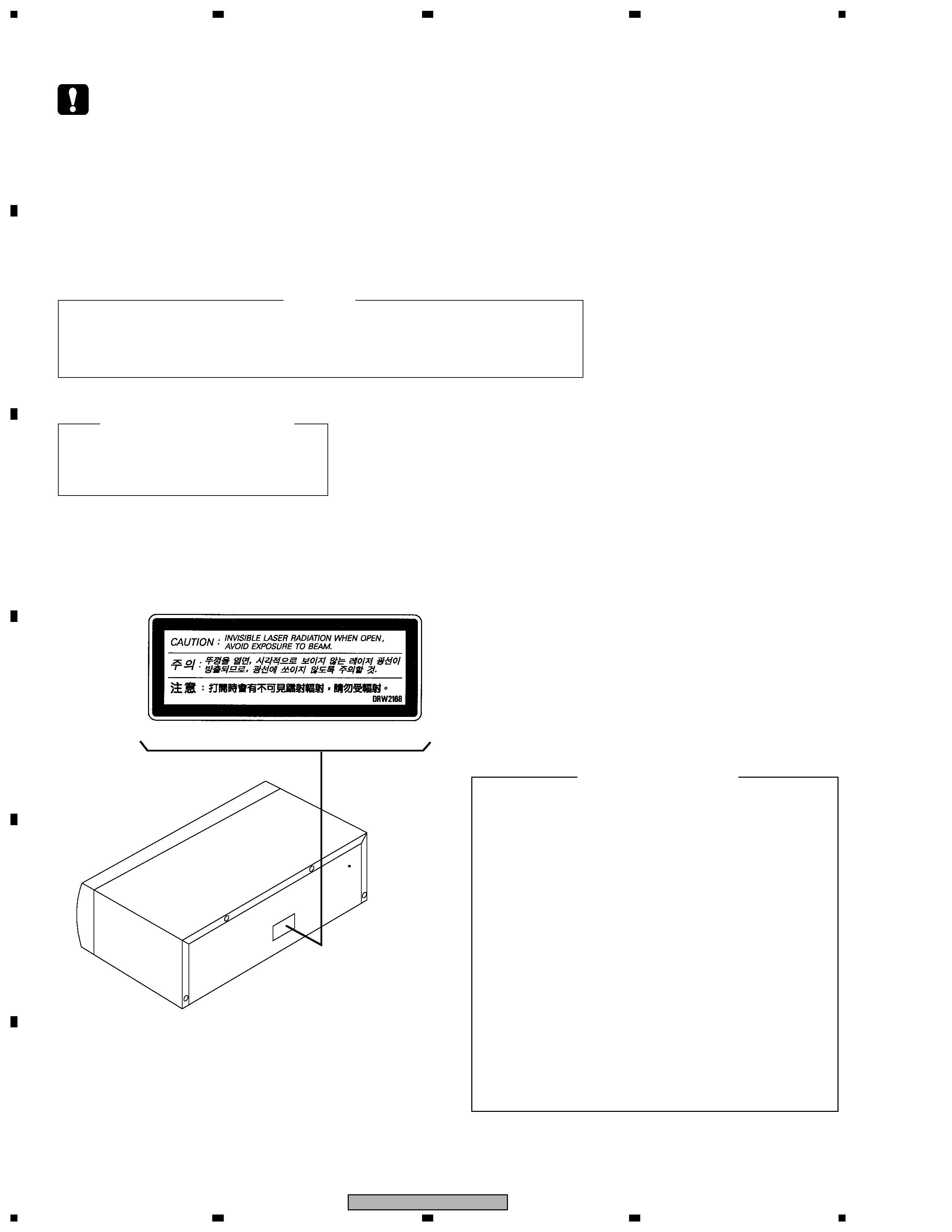
LABEL CHECK
REAR
(DRW2168)
1. Laser Interlock Mechanism
The position of the switch (S651) for detecting loading
state is detected by the system microprocessor, and
the design prevents laser diode oscillation when the switch (S651)
is not on CLMP terminal side (CLMP signal is OFF or high level).
Thus, the interlock will no longer function if the switch (S651)
is deliberatery set to CLMP terminal side. (low level)
The interlock also does not function in the test mode ].
Laser diode oscillation will continue, if pin 33 of
CXA1782CQ (IC151) on the MOTHER BOARD ASSY
is connected to GND, or pin 26 of IC351 (LDON) is connected
to low level (ON), or else the terminals of Q151 are shorted
to each other (fault condition).
2. When the cover is opened, close viewing of the objective lens with
the naked eye will cause exposure to a Class 1 laser beam.
3
1
23
4
1
2
3
4
C
D
F
A
B
E
PD-M427
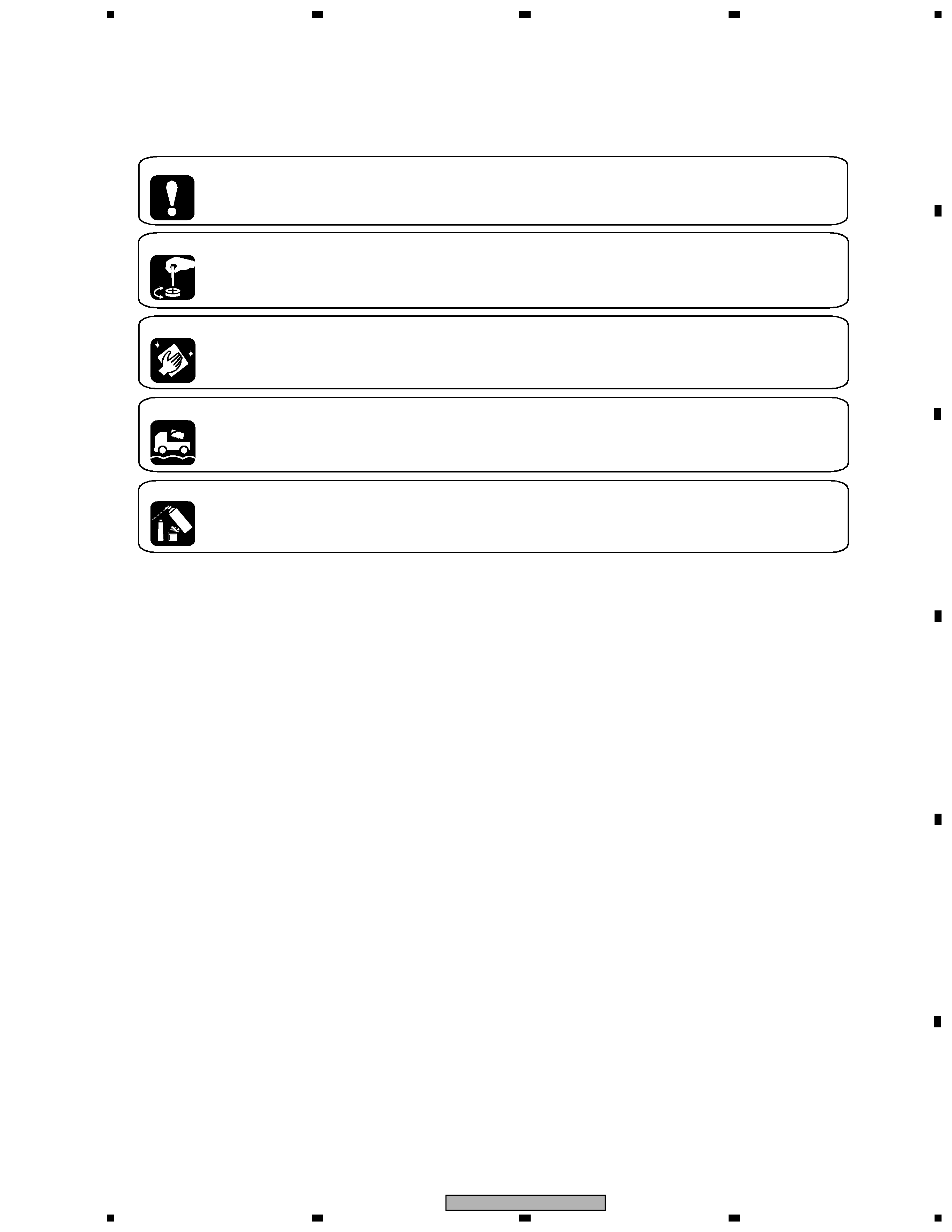
[ Important symbols for good services ]
In this manual, the symbols shown-below indicate that adjustments, settings or cleaning should be made securely.
When you find the procedures bearing any of the symbols, be sure to fulfill them:
2. Adjustments
To keep the original performances of the product, optimum adjustments or specification confirmation is indispensable.
In accordance with the procedures or instructions described in this manual, adjustments should be performed.
3. Cleaning
For optical pickups, tape-deck heads, lenses and mirrors used in projection monitors, and other parts requiring cleaning,
proper cleaning should be performed to restore their performances.
5. Lubricants, glues, and replacement parts
Appropriately applying grease or glue can maintain the product performances. But improper lubrication or applying
glue may lead to failures or troubles in the product. By following the instructions in this manual, be sure to apply the
prescribed grease or glue to proper portions by the appropriate amount.For replacement parts or tools, the prescribed
ones should be used.
4. Shipping mode and shipping screws
To protect the product from damages or failures that may be caused during transit, the shipping mode should be set or
the shipping screws should be installed before shipping out in accordance with this manual, if necessary.
1. Product safety
You should conform to the regulations governing the product (safety, radio and noise, and other regulations), and
should keep the safety during servicing by following the safety instructions described in this manual.

4
1
23
4
12
3
4
C
D
F
A
B
E
PD-M427
SAFETY INFORMATION ...................................................................................................................................... 2
1. SPECIFICATIONS .................................................................................................................................................5
2. EXPLODED VIEWS AND PARTS LIST ............................................................................................................... 6
2.1 PACKING SECTION
............................................................................................................................... 6
2.2 EXTERIOR (1/2)SECTION ............................................................................................................................. 8
2.3 EXTERIOR (2/2)SECTION
.................................................................................................
................................................................................................. 9
2.4 SINGLE MECHANISM SECTION
.................................................................................................
.................. 10
3. SCHEMATIC DIAGRAM
.........................................................................................
.........................................................................................
... 12
3.1 MOTHER, DISPLAY and SW BOARD ASSYS ........................................................................................... 12
3.2 WAVEFORMS MOTHER BOARD ASSY ..................................................................................................... 14
4. PCB CONNECTION DIAGAM ............................................................................................................................ 16
4.1 MECHA, DISPLAY, SW and HP BOARD ASSYS
16
.......................................................................................
4.2 MOTHER BOARD ASSY
..........................................................................................
..........................................................................................
17
6.1 PREPARATIONS
..........................................................................................
..........................................................................................
..........................................................................................
22
6.2 ADJUSTMENT
..........................................................................................
..........................................................................................
..........................................................................................
23
5. PCB PARTS LIST ............................................................................................................................................... 19
6. ADJUSTMENT .................................................................................................................................................... 22
7. GENERAL INFORMATION ................................................................................................................................ 30
7.1 DISPLAY
.................................................................................................................................................. 30
7.2 CLEANING
............................................................................................................................................ 31
7.3 BLOCK DIAGRAM
.................................................................................................................................... 31
8. PANEL FACILITIES ............................................................................................................................................ 32
CONTENTS
5
1
23
4
1
2
3
4
C
D
F
A
B
E
PD-M427
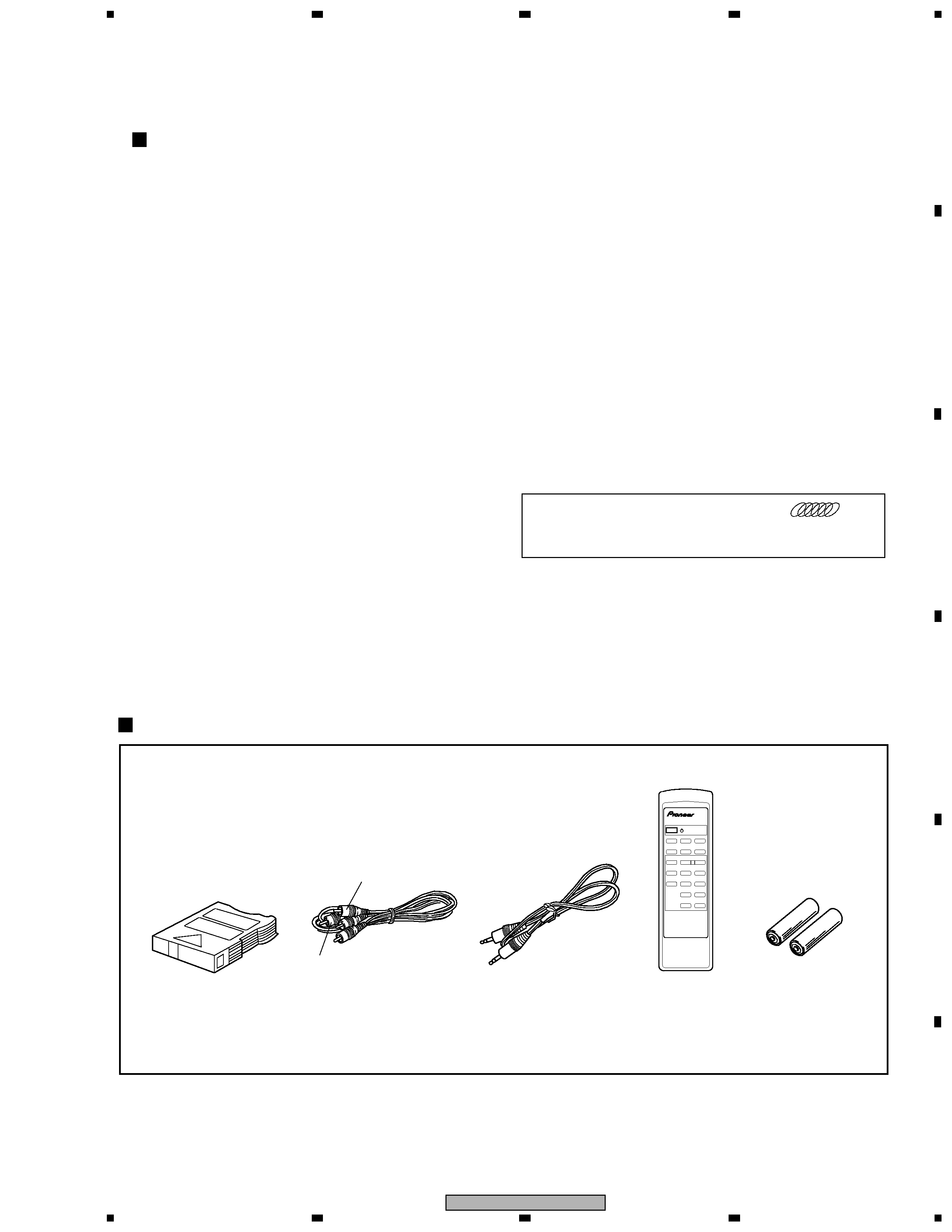
White
Red
Dry cell batteries
(AAA/R03)
Remote control unit
(PWW1149)
(CU-PD104)
Control cable
(PDE-319)
(L= 1 m)
Output cable
(PDE1315)
(L= 1 m)
6-Compact disc magazine
(PXA1617)
· Operating instructions
'
Î
STANDBY/ON
DISC 1
DISC 2
DISC 3
DISC 4
DISC 5
DISC 6
78
3
1¡
4¢
RANDOM
HILITE
PROGRAM
DELETE
CLEAR
CHECK
MULTI
COMPACT DISC PLAYER
REMOTE CONTROL UNIT
CU-PD104
Accessories
SPECIFICATIONS
General
Type ............................... Compact disc digital audio system
Power requirements
Multi-voltage model ...................... AC 110-127/220-240 V
(Switchable), 50/60Hz
Power consumption
Australian and New Zealand models ........................ 12 W
Operating temperature ...................................... +5
°C-+35°C
(+41
°F +95°F)
Weight (without package) ........................ 3.7 kg (8 lb, 3 oz.)
External dimensions ............ 420(W) x 294 (D) x 105 (H) mm
16-9/16 (W) x 11-9/16 (D) x 4-1/8 (H) in
Audio section
Frequency response ...................................... 2 Hz 20 kHz
Output voltage ............................................................. 2.0 V
Wow and flutter ................................ Limit of measurement
(0.001% W.PEAK) or less (EIAJ)
Channels .................................................. 2-channel (stereo)
Output terminal
Audio line output
Control input/output jacks
Accessories
· Remote control unit
..............................
..............................
..............................
1
· Size AAA/R03 dry cell batteries
............ 2
· Six-compact-disc magazine ............................................. 1
· Control cable ................................................................... 1
· Output cable ................................................................... 1
· Operating instructions .................................................... 1
NOTE:
Specifications and design subject to possible modification
without notice, due to improvements.
The Magazine Type Multi CD Players with
mark
and the Magazines with the same mark are compatible
for 5 inch (12 cm) discs.
1. SPECIFICATIONS