ORDER NO.
PIONEER CORPORATION 4-1, Meguro 1-chome, Meguro-ku, Tokyo 153-8654, Japan
PIONEER ELECTRONICS (USA) INC. P.O. Box 1760, Long Beach, CA 90801-1760, U.S.A.
PIONEER EUROPE NV Haven 1087, Keetberglaan 1, 9120 Melsele, Belgium
PIONEER ELECTRONICS ASIACENTRE PTE. LTD. 253 Alexandra Road, #04-01, Singapore 159936
PIONEER CORPORATION 2006
RRV3499
T ZZK SEPT. 2006 Printed in Japan
MULTI COMPACT DISC PLAYER
PD-M426
PD-M406
THIS MANUAL IS APPLICABLE TO THE FOLLOWING MODEL(S) AND TYPE(S).
Model No.
Order No.
Remarks
PD-M426/WYXJ/2
RRV1868
¶ This service manual should be used together with the following manual(s):
¶ For SPECIFICATIONS and PANEL FACILITIES, refer to the operating instructions.
Model
Type
Power Requirement
Remarks
PD-M426
WYXJ57
AC 220 V to 240 V
PD-M406
WYXJ57
AC 220 V to 240 V
2
1
23
4
12
3
4
C
D
F
A
B
E
PD-M426
REAR
This service manual is intended for qualified service technicians ; it is not meant for the casual do-
it-yourselfer. Qualified technicians have the necessary test equipment and tools, and have been
trained to properly and safely repair complex products such as those covered by this
manual.Improperly performed repairs can adversely affect the safety and reliability of the product
and may void the warranty. If you are not qualified to perform the repair of this product properly and
safely, you should not risk trying to do so and refer the repair to a qualified service technician.
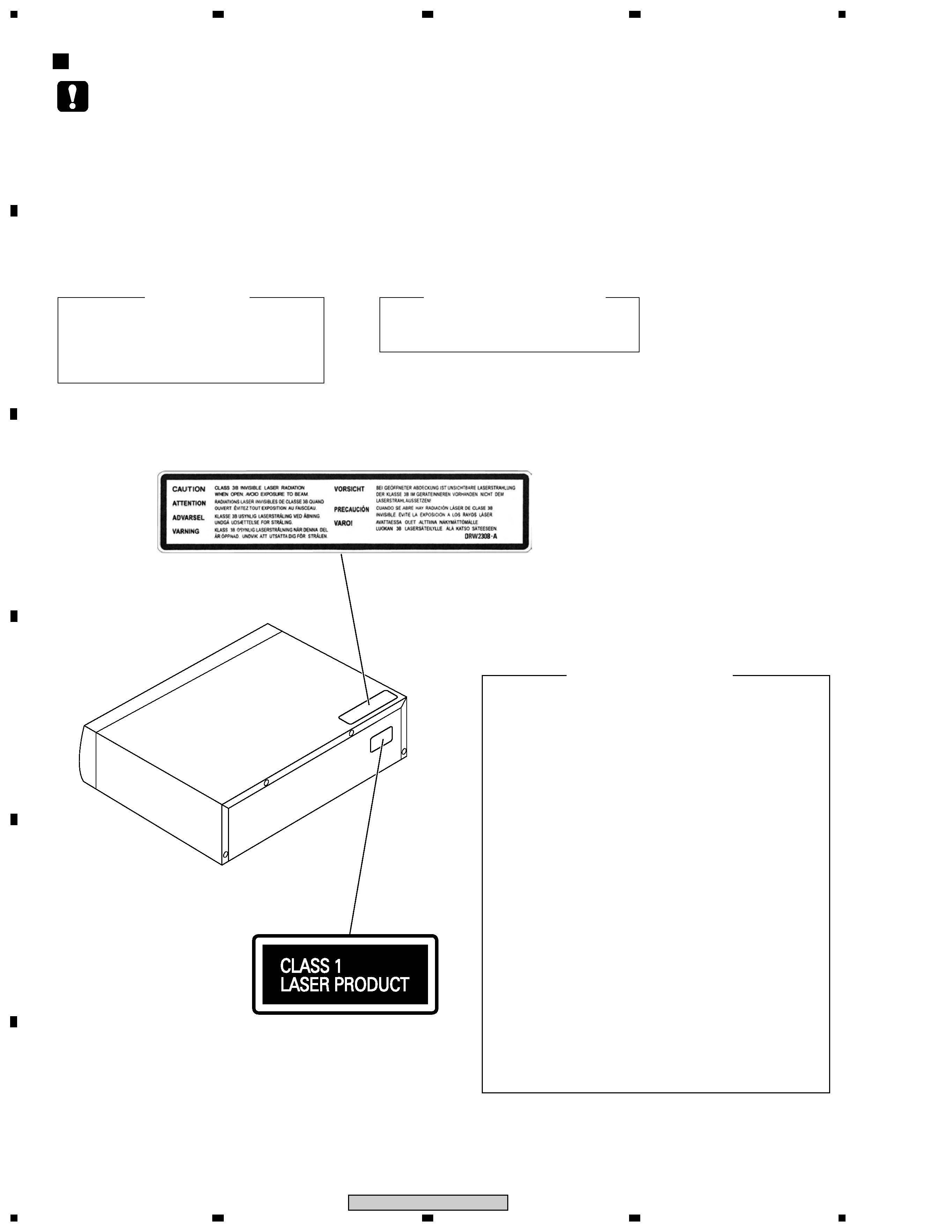
LASER DIODE CHARACTERISTICS
MAXIMUM OUTPUT POWER : 7 mW
WAVELENGTH : 780 to 785 nm
IMPORTANT
THIS PIONEER APPARATUS CONTAINS
LASER
OF
CLASS
1.
SERVICING OPERATION OF THE APPARATUS
SHOULD BE DONE BY A SPECIALLY
INSTRUCTED PERSON.
Additional Laser Caution
1. Laser Interlock Mechanism
The ON/OFF (ON : low level, OFF : high level)
status of S601 (LPS1) and S602 (LPS2)
switches for detecting the loading state is
detected by the system microprocessor, and
the design prevents laser diode oscillation
except when both switches S601 and S602
are ON (low level or clamped state).
Thus, interlock will no longer function if
switches S601 (LPS1) and S602 (LPS2) are
deliberately shorted (low level). The interlock
also does not function in the test mode *.
Laser diode oscillation will continue, if pin 33
of CXA1782CQ (IC151) on the MOTHER
BOARD ASSY is connected to GND, or pin
50 of IC351 (LDON) is connected to low level
(ON), or else the terminals of Q151 are shorted
to each other (fault condition).
2. When the cover is opened with the servo
mechanism block removed to be turned over,
close viewing of the objective lens with the
naked eye will cause exposure to a Class 1
laser beam.
LABEL CHECK
: Refer to page 22 on the service manual RRV1868.
DRW2308
Printed on the Rear Panel
SAFETY INFORMATION
3
5
67
8
5
6
7
8
C
D
F
A
B
E
PD-M426
Part No.
Ref. No. Mark
Symbol and Description
PD-M426
PD-M426
PD-M406
Remarks
/WYXJ/2
/WYXJ57
/WYXJ57
PCB ASSEMBLIES
NSP
SUB BOARD Assy
PWX1337
PWX1337
PWX1335
P7- 19
FUNCTION BOARD Assy
PWZ2769
PWZ2769
PWZ2768
P7- 20
MOTHER BOARD Assy
PWM2156
PWM2156
PWM2153
PACKING SECTION
P5- 1
Control Cable (for SR)(L=1m)
Not used
Not used
XDE3063
P5- 2
Output Cable (for AUDIO)(L=1m)
PDE1248
XDE3047
XDE3047
P5- 3
Remote Control Unit
PWW1107
PWW1149
Not used
P5- 4
Battery Cover
PZN1010
PZN1010
Not used
P5- 5
6-Compact Disc Magazine
PXA1575
PXA1617
PXA1617
P5- 6
Operating Instructions (Geman/Italian/Dutch/
PRD1018
PRD1039
PRD1039
Swedish/Spanish/Portuguese)
P5- 6
Operating Instructions (English/French)
PRE1257
PRE1273
PRE1273
P5- 9
CD Packing Case
PHG2309
PHG2354
PHG2353
P5- 11
NSP
Dry Cell Battery (AAA/R03)
VEM-022
VEM-022
Not used
P5- 12
NSP
Warranty Card
ARY7009
ARY7065
ARY7065
Label(WEEE)
Not used
ARW7322
Not used
*2
NSP
Label WY57
Not used
PRW1600
PRW1600
IEC65-7 Caution
Not used
ARM7106
ARM7106
EXTERIOR SECTION
P7- 2
32P F.F.C/30V
PDD1041
PDD1041
Not used
P7- 2
30P F.F.C/30V
Not used
Not used
PDD1049
P7- 3
Power Transformer
PTT1236
PTT1365
PTT1365
P7- 4
AC Power Cord
PDG1003
PDG1043
PDG1043
P7- 5
Bonnet
PYY1149
PYY1299
PYY1299
P7- 9
Function Panel
PNW2726
PNW2886
PNW2885
P7- 11
Name Plate
PAM1608
PAM1776
PAM1776
P7- 15
Display Window
PAM1846
PAM1846
PAM1845
P7- 21
Screw
BBZ30P060FMC
BBZ30P060FTC
BBZ30P060FTC
P7- 22
Screw
BBZ30P080FZK
BBZ30P080FTC
BBZ30P080FTC
P7- 23
Screw
PPZ30P120FMC
PPZ30P120FTC
PPZ30P120FTC
P7- 24
Screw
FBT40P080FZK
FBT40P080FTB
FBT40P080FTB
P7- 28
Screw
PDZ30P050FMC
PDZ30P050FTC
PDZ30P050FTC
P7- 31
Rear Base
PNA2413
PNA2469
PNA2468
P7-38
Caution Label
VRW1094
Not used
Not used
P7-39
Caution Label (HE)
PRW1233
Not used
Not used
P7- 40
NSP
Locking Card Spacer
PEC1036
Not used
Not used
P7- 40
Locking Card Spacer
Not used
AEC7492
AEC7492
Laser Caution (7L)
Not used
DRW2308
DRW2308
*1
Label(WEEE)
Not used
ARW7322
ARW7322
*3
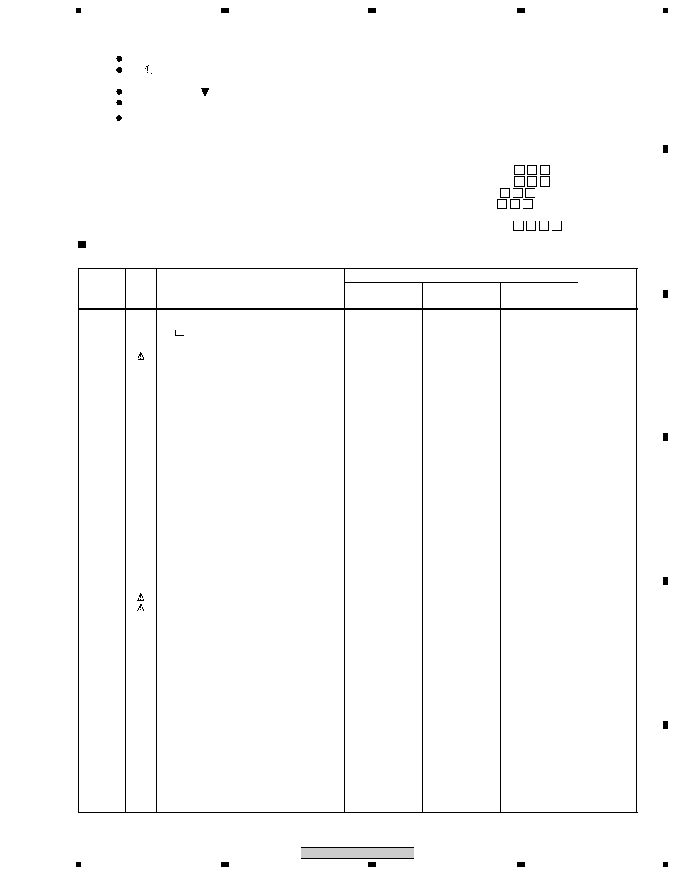
1. CONTRAST OF MISCELLANEOUS PARTS
jp
f
y
For the applying amount of lubricants or glue, follow the instructions in this manual.
(In the case of no amount instructions, apply as you think it appropriate.)
Parts marked by "NSP" are generally unavailable because they are not in our Master Spare Parts List.
The
mark found on some component parts indicates the importance of the safety factor of the part.
Therefore, when replacing, be sure to use parts of identical designation.
Screws adjacent to
mark on product are used for disassembly.
Reference Nos. indicate the pages and Nos. in the service manual for the base model.
NOTES:
·When ordering resistors, first convert resistance values into code form as shown in the following examples.
Ex.1 When there are 2 effective digits (any digit apart from 0), such as 560 ohm and 47k ohm (tolerance is shown by J=5%,
and K=10%).
560
56
× 101
561 ........................................................ RD1/4PU 5 6 1 J
47k
47
× 103
473 ........................................................ RD1/4PU 4 7 3 J
0.5
R50 ..................................................................................... RN2H R 5 0 K
1
1R0 ..................................................................................... RS1P 1 R 0 K
Ex.2 When there are 3 effective digits (such as in high precision metal film resistors).
5.62k
562
× 101
5621 ...................................................... RN1/4PC 5 6 2 1 F
CONTRAST TABLE
PD-M426/WYXJ57, PD-M406/WYXJ57 and PD-M426/WYXJ/2 are constructed the same except for the following :
Notes :
÷ For PCB ASSEMBLIES, Refer to "CONTRAST OF PCB ASSEMBLIES".
*1 : Refer to "SAFETY INFORMATION".
*2 : Remote Control Umit
*3 : Bonnet
4
1
23
4
12
3
4
C
D
F
A
B
E
PD-M426
Mark
Symbol and Description
Part No.
Remarks
PWM2156
PWM2153
D392D394
Not used
1SS254
*1
L391
Not used
LAU1R0J
*1
C393
Not used
CCCSL101J50
*1
C399
Not used
CKCYF103Z50
*1
R391
Not used
RD1/4PU244J
*1
R392
Not used
RD1/4PU102J
*1
CN351 32P FFC CONNECTOR
HLEM32S-1
Not used
CN351 30P FFC CONNECTOR
Not used
HLEM30S-1
JA391, JA392 SR JACK
Not used
RKN1004
*1
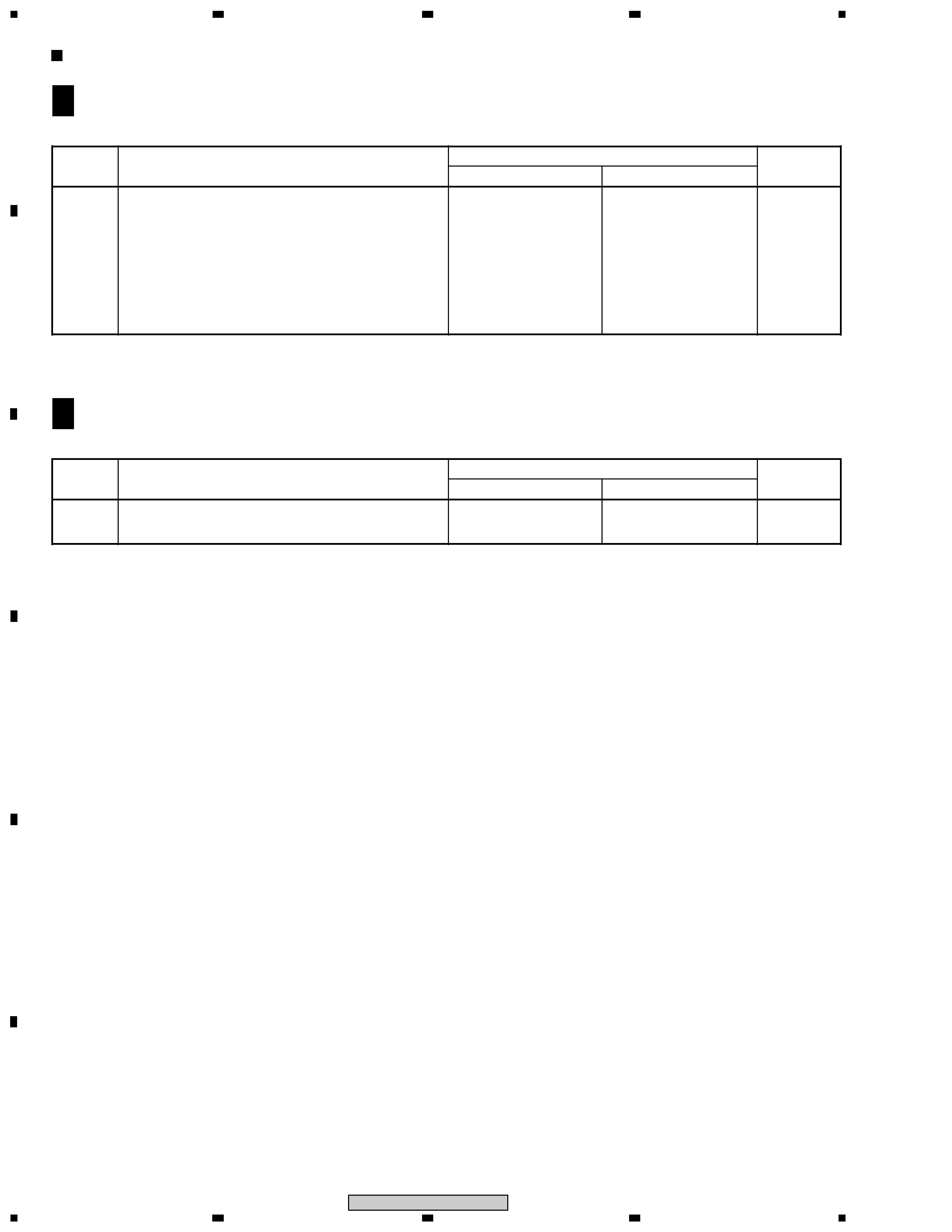
MOTHER BOARD ASSY
PWM2153 and PWM2156 are constructed the same except for the following :
F
A
CONTRAST OF PCB ASSEMBLIES
*1 : Refer to "3. SCHEMATIC DIAGRAM" (C-7) on the service manual RRV1868.
Mark
Symbol and Description
Part No.
Remarks
PWZ2769
PWZ2768
CN701 32P FFC CONNECTOR
9607S-32F
Not used
CN701 30P FFC CONNECTOR
Not used
9607S-30F
Remote Sensor
SBX1976-51
Not used
FUNCTION BOARD ASSY
PWZ2768 and PWZ2769 are constructed the same except for the following :
F
E