
Operating instructions
Mode d'emploi
Bedienungsanleitung
Istruzioni per l'uso
Gebruiksaanwijzing
Manual de instrucciones
Floor stand
Support de base
Bodenständer
Supporto per display
Vloerstandaard
Soporte para colocar en el suelo
PDK-FS07
2
En
Thank you for buying Pioneer's product.
Please read through the Operating Instructions to learn how
to operate your model safely and properly.
Please be advised to keep the Operating Instructions in
your place for future reference.
Contents
Installation
¶ Consult your dealer if you encounter any difficulties
with this installation.
¶ Pioneer is not liable for any damage resulting from improper
installation, improper use, modification, or natural disasters.
Cautions
This product is a floor stand exclusively designed for
Plasma Displays (PDP-507XD / PDP-507XA / PDP-507XG /
PDP-507XDA / PDP-427XD / PDP-427XA / PDP-427XG /
PDP-427XDA / PDP-4270XD / PDP-4270XA) from Pioneer.
Note that it is not designed for use with any other equip-
ment. For further information, please contact the store
where you purchased your display.
Do not install or modify the product other than specified.
Do not use this stand for a Plasma Display other than those
designated and do not modify it or use it for other
purposes.
Improper installation is extremely dangerous because it
may result in it falling over or other accident.
Installation Location
· When selecting the location in which the stand is to be
placed, be sure to select a location with a surface
sufficiently strong to bear the weight of the stand and
Plasma Display. (Product weight is listed on page 8)
· Make sure the installation location is a level, flat, and
stable surface and take proper precautions when
installing it to make sure its weight is evenly distributed.
· Depending on the type of surface on which the stand is
placed, the legs may leave marks on the surface, and this
should be taken into consideration when selecting the
place in which the stand is to be placed.
· Do not install it outdoors, at a hot spring, or near a beach.
· Do not install the stand where it may be subjected to
vibration or shock.
Assembling and Installation
· Assemble the stand in accordance with the assembly
instructions and securely attach all screws at the
designated locations.
There have been cases where unforeseen accidents
such as the equipment breaking or falling over
occurred after the installation of the display because
the stand was not installed as instructed.
· The display must always be installed by two or more
people to assure it is installed safely.
· Before installation, turn off the power for the display
and peripheral devices then remove the power cord
plug from the power outlet.
After Installation
· Never lean on the Plasma Display or apply heavy pres-
sure to the stand.
· Prevent accidents caused by the product falling over by
taking reliable measures to prevent it from falling over
(see page 7).
· Do not move the stand with the Plasma Display etc. still
attached.
CAUTION
This symbol refers to a hazard or unsafe practice which
can result in personal injury or property damage.
Cautions ................................................................... 2
List of parts and equipment included ................... 3
Installation and assembly instructions ................. 4
Preventing equipment from falling over ............... 7
Specifications .......................................................... 8
Dimensions diagram ............................................... 8
IMPORTANT NOTICE
Record the model number and serial number of this
equipment below.
Model No. PDK-FS07
Serial No.
Keep this number for future use.
WARNING
To prevent a fire hazard, do not place any naked
flame sources (such as a lighted candle) on the
equipment.
D3-4-2-1-7a_A_En
3
En
English
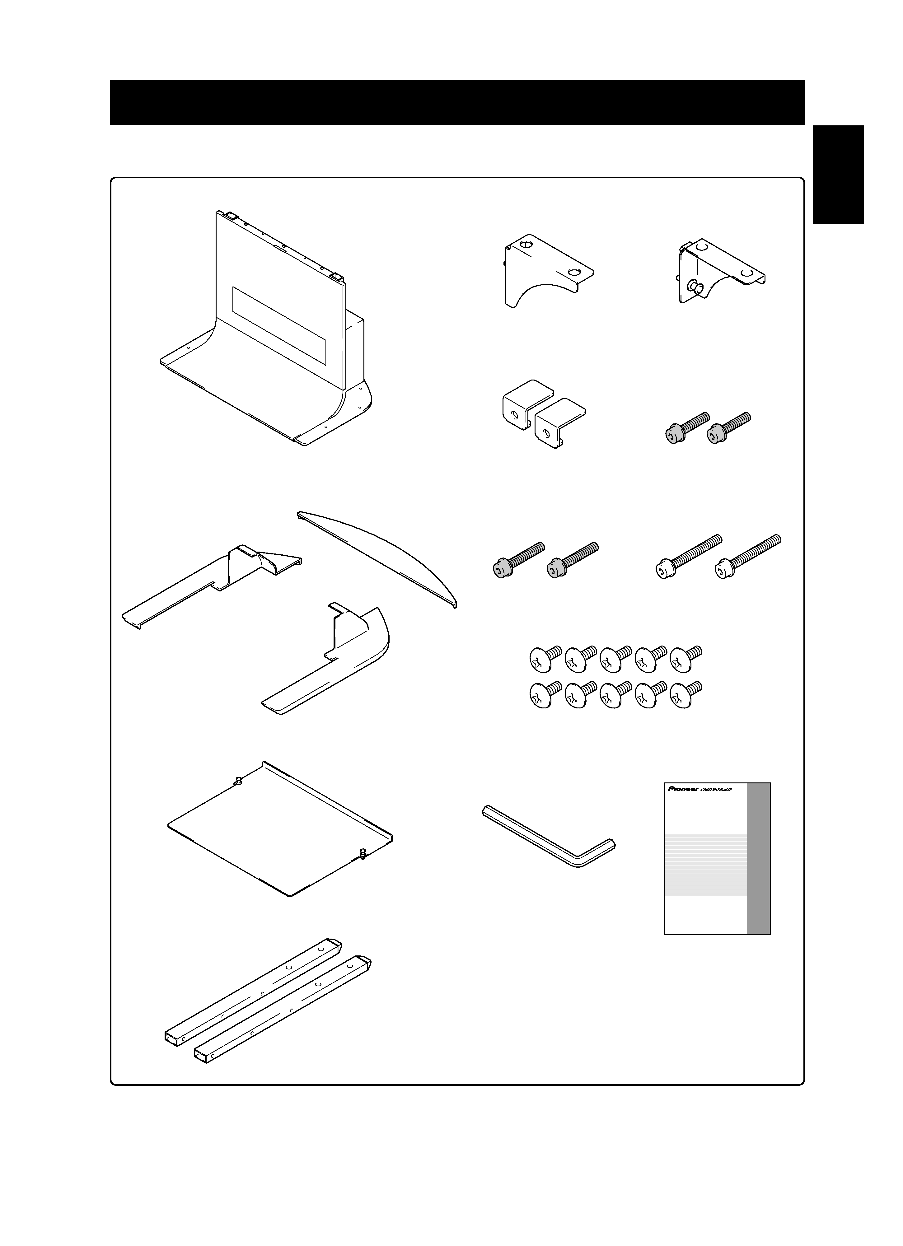
· Stand x1
· Shelf panel x1
· Base cover L x1
· Base cover R x1
· Base cover rear x1
· Middle hexagonal bolts
(M8 x 40 mm [1-9/16 inch]:
black) x2
· Screw (M5 x 10 mm [13/32 inch]) x10
· Hexagonal wrench x1
(Opposite side 6 mm for M8 use)
· Operating instructions
(this document) x1
· Support column x2
· Support column stopper x2
· Shelf support R x1
· Shelf support L x1
List of parts and equipment included
Be sure to check that all the parts and equipment listed below have been included before beginning to assemble your stand.
· Note that a Philips screwdriver (not included) is required for assembly.
· Long hexagonal bolts
(M8 x 60 mm [2-3/8 inch]:
silver) x2
Operating instructions
Mode d'emploi
Bedienungsanleitung
Istruzioni per l'uso
Gebruiksaanwijzing
Manual de instrucciones
Floor stand
Support de base
Bodenständer
Supporto per display
Vloerstandaard
Soporte para colocar en el suelo
PDK-FS07
· Short hexagonal bolts
(M8 x 30 mm [1-3/16 inch]:
black) x2
4
En
Installation and assembly instructions
1 Attaching the support columns to the stand.
B When installing the 50 inch display model
(with under speaker)
Attach the support column stoppers to the high position notches
on the back of the stand and fix them in place with screws (M5
x 10 mm [13/32 inch]). (2 locations on the right and left)
The same applies to support column attachment method
A.
Support column
stopper
Screw
(M5 x 10 mm [13/32 inch])
The attachment procedure varies according to the type
and form of the Plasma Display to be attached. Perform
this attachment using either procedure
A, B or C.
Note
Be sure to carefully store the unused support column stopper,
the screws, the bolts, the hexagonal wrench, and the Operating
Instructions together.
A When installing the 42 inch display model
Insert the support columns into the stand and fix them in
place with screws (M5 x 10 mm [13/32 inch]). (8 locations)
Install each support column so that the side with the symbol
' is forward and the end with the plastic end cap (pointed) is
upwards.
Table of support column position and parts
for each Plasma Display
Support column
stopper
Screw (M5 x 10 mm [13/32 inch])
C When installing the 50 inch display model
(without under speaker)
Attach the support column stoppers to the low position notches
on the back of the stand and fix them in place with screws (M5
x 10 mm [13/32 inch]). (2 locations on the right and left)
The same applies to support column attachment method
A.
Side with the
symbol
' is
forward.
End with end cap
points upwards.
Support column
Screw
(M5 x 10 mm
[13/32 inch])
5
En
English
3 Use the short, the middle or the long hexagonal
bolts to fix the Plasma Display to the support
column (4 locations).
Please install starting with the bolts on the top.
When installing the 50 inch display model
Use the following bolts to fix it with the hexagonal wrench.
Top .......... Middle hexagonal bolts (M8 x 40 mm [1-9/16 inch]: black)
Bottom ... Short hexagonal bolts (M8 x 30 mm [1-3/16 inch]: black)
Installation and assembly instructions
It you are attaching speakers, do so at this stage.
See the installation instructions provided with your
speakers for instructions on how to install them.
2 Attach Plasma Display to support column.
Fit the stand's support columns into the slots in the center of
the bottom of the Plasma Display then slowly insert them
directly into the slots. Be extremely careful not to insert the
support columns of the stand into any part of the Plasma
Display other than the stand insertion slots. Note that doing so
might damage the Plasma Display panel or its ports or result
in the warping of the stand.
If the Plasma Display is fitted with handles, it is usually best to
hold the display by its handles when attaching it to the
support column.
Be sure to work with at least one other person
when attaching the display.
Be careful not to allow your fingers get caught
between the display and support column.
Caution
Line up the column supports
with the bottom of the Plasma
Display as indicated in the
accompanying diagram.
When installing the 42 inch display model
Use the following bolts to fix it with the hexagonal wrench.
Top .......... Long hexagonal bolts (M8 x 60 mm [2-3/8 inch]: silver)
Bottom ... Short hexagonal bolts (M8 x 30 mm [1-3/16 inch]: black)
Short hexagonal bolts
(M8 x 30 mm
[1-3/16 inch]: black)
Short hexagonal bolts
(M8 x 30 mm
[1-3/16 inch]: black)
Long hexagonal bolts
(M8 x 60 mm [2-3/8 inch]: silver)
Middle hexagonal bolts
(M8 x 40 mm [1-9/16 inch]: black)