ORDER NO.
PIONEER CORPORATION 4-1, Meguro 1-chome, Meguro-ku, Tokyo 153-8654, Japan
PIONEER ELECTRONICS (USA) INC. P.O. Box 1760, Long Beach, CA 90801-1760, U.S.A.
PIONEER EUROPE NV Haven 1087, Keetberglaan 1, 9120 Melsele, Belgium
PIONEER ELECTRONICS ASIACENTRE PTE. LTD. 253 Alexandra Road, #04-01, Singapore 159936
PIONEER CORPORATION 2001
ARP3109
HAND WRITING DEVICE
PDK-50HW2
1. SAFETY INFORMATION ...................................... 3
2. EXPLODED VIEWS AND PARTS LIST ................ 4
3. SCHEMATIC DIAGRAM ...................................... 10
4. PCB CONNECTION DIAGRAM .......................... 45
5. PCB PARTS LIST ............................................... 74
6. ADJUSTMENT .................................................... 76
CONTENTS
7. GENERAL INFORMATION ................................ 77
7.1 Circuit Description ....................................... 77
7.1.1 Block Diagram ................................... 77
7.2.2 Block Diagram of Assy for each
LED-A to LED-G ................................ 78
7.3.3 Block Diagram of Assy for each
SENSOR-H to SENSOR-N ............... 79
8. PANEL FACILITIES AND SPECIFICATIONS .... 80
T ZZB NOV. 2001 Printed in Japan
For details, refer to "Important symbols for good services" on the next page.
THIS MANUAL IS APPLICABLE TO THE FOLLOWING MODEL(S) AND TYPE(S).
Type
Model
PDK-50HW2
UCYVLDP
AC100 240V
Power Requirement
Remarks
with AC adapter
PDK-50HW2
2
[ NOTES ON SERVICING ]
7 CLEARNING
Before shipping out the product, be sure to clean the following positions by using the prescribed cleaning tools:
Position to be cleaned
Cleaning tools
Pickup leneses
Cleaning liquid : GEM1004
Cleaning paper : GED-008
Position to be cleaned
Cleaning tools
Cassette heads
Pinch rollers
Cleaning paper : GED-008
Capstans
Position to be cleaned
Cleaning tools
Fans
Cleaning paper : GED-008
[ Important symbols for good services ]
In this manual, the symbols shown-below indicate that adjustments, settings or cleaning should be made securely.
When you find the procedures bearing any of the symbols, be sure to fulfill them:
2. Adjustments
To keep the original performances of the product, optimum adjustments or specification confirmation is indispensable.
In accordance with the procedures or instructions described in this manual, adjustments should be performed.
3. Cleaning
For optical pickups, tape-deck heads, lenses and mirrors used in projection monitors, and other parts requiring cleaning,
proper cleaning should be performed to restore their performances.
5. Lubricants, glues, and replacement parts
Appropriately applying grease or glue can maintain the product performances. But improper lubrication or applying
glue may lead to failures or troubles in the product. By following the instructions in this manual, be sure to apply the
prescribed grease or glue to proper portions by the appropriate amount.For replacement parts or tools, the prescribed
ones should be used.
4. Shipping mode and shipping screws
To protect the product from damages or failures that may be caused during transit, the shipping mode should be set or
the shipping screws should be installed before shipping out in accordance with this manual, if necessary.
1. Product safety
You should conform to the regulations governing the product (safety, radio and noise, and other regulations), and
should keep the safety during servicing by following the safety instructions described in this manual.
PDK-50HW2
3
1. SAFETY INFORMATION
This service manual is intended for qualified service technicians; it is not meant for the casual
do-it-yourselfer. Qualified technicians have the necessary test equipment and tools, and have been
trained to properly and safely repair complex products such as those covered by this manual.
Improperly performed repairs can adversely affect the safety and reliability of the product and may
void the warranty. If you are not qualified to perform the repair of this product properly and safely, you
should not risk trying to do so and refer the repair to a qualified service technician.
WARNING
This product contains lead in solder and certain electrical parts contain chemicals which are known to the state of California to
cause cancer, bir th defects or other reproductive harm.
Health & Safety Cod e Section 25249.6 Proposition 65
NOTICE
(FOR CANADIAN MODEL ONLY)
Fuse symbols
(fast operating fuse)
and/or
(slow operating fuse) on PCB indicate that replacement
parts must be of identical designation.
REMARQUE
(POUR MODÈLE CANADIEN SEULEMENT)
Les symboles de fusible
(fusible de type rapide)
et/ou
(fusible de type lent) sur CCI indiquent que
les pièces de remplacement doivent avoir la même désignation.
ANY MEASUREMENTS NOT WITHIN THE
LIMITS OUTLINED ABOVE ARE INDICATIVE
OF A POTENTIAL SHOCK HAZARD AND
MUST BE CORRECTED BEFORE RETURN-
ING THE APPLIANCE TO THE CUSTOMER.
2. PRODUCT SAFETY NOTICE
Many electrical and mechanical parts in the appliance
have special safety related characteristics. These are
often not evident
from visual
inspection nor the
protection afforded by them necessarily can be obtained
by using replacement components rated for voltage,
wattage, etc. Replacement parts which have these
special safety characteristics are identified in this
Service Manual.
Electrical components having such features are
identified by marking with a
on the schematics and
on the parts list in this Service Manual.
The use of a substitute replacement component which
does not have the same safety characteristics as the
PIONEER recommended replacement one, shown in the
parts list in this Service Manual, may create shock, fire,
or other hazards.
Product Safety is continuously under review and new
instructions are issued from time to time. For the latest
information, always consult the current PIONEER
Service Manual. A subscription to, or
additional copies
of, PIONEER Service Manual may be obtained at a
nominal charge from PIONEER.
(FOR USA MODEL ONLY)
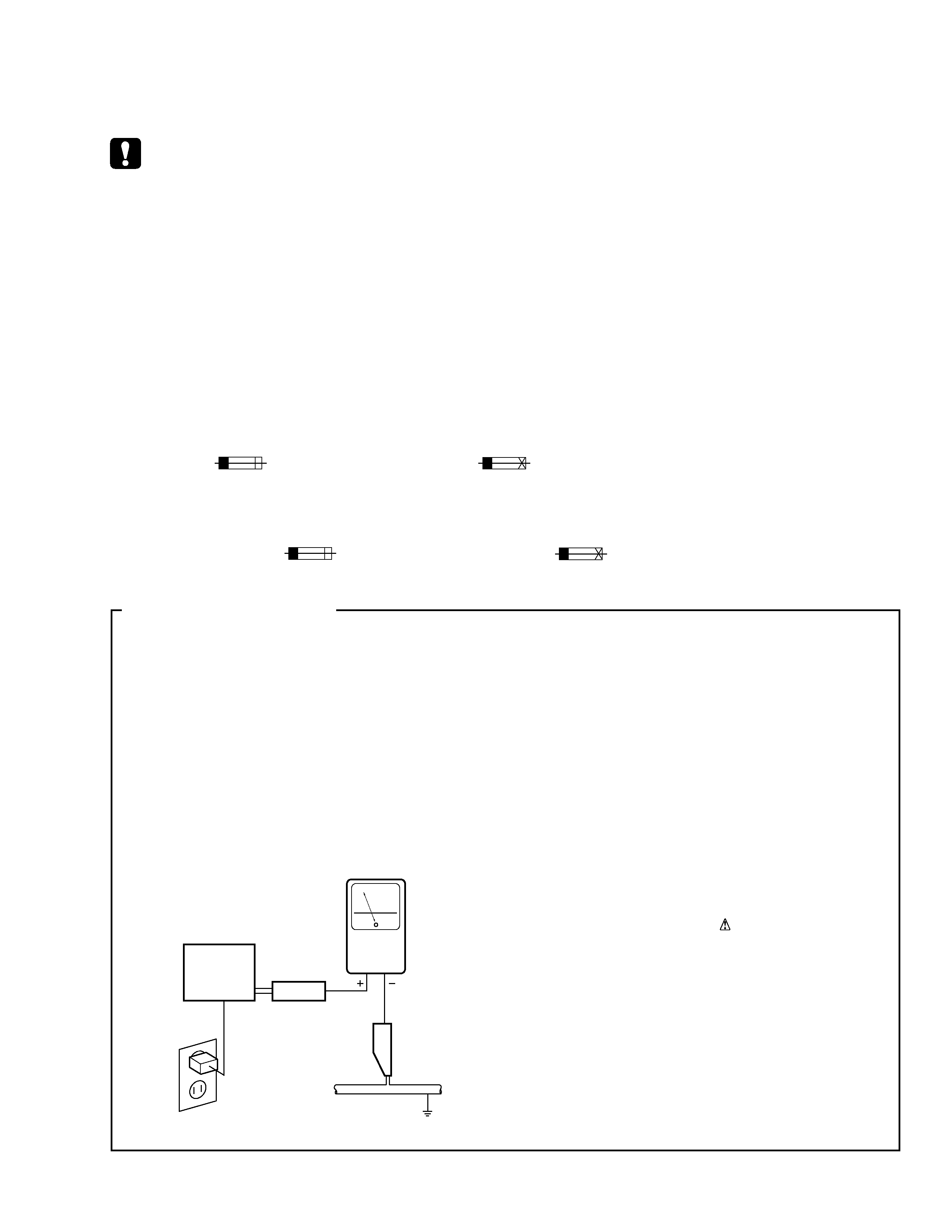
1. SAFETY PRECAUTIONS
The following check should be performed for the
continued protection of the customer and service
technician.
LEAKAGE CURRENT CHECK
Measure leakage current to a known earth ground
(water pipe, conduit, etc.) by connecting a leakage
current tester such as Simpson Model 229-2 or
equivalent between the earth ground and all exposed
metal parts of the appliance (input/output terminals,
screwheads, metal overlays, control shaft, etc.). Plug
the AC line cord of the appliance directly into a 120V
AC 60 Hz outlet and turn the AC power switch on. Any
current measured must not exceed 0.5 mA.
Device
under
test
Leakage
current
tester
Earth
ground
Reading should
not be above
0.5 mA
Also test with
plug reversed
(Using AC adapter
plug as required)
Test all
exposed metal
surfaces
AC Leakage Test
4
PDK-50HW2
(BATTERY)
1 (
×8)
10
9
8
14
6
5
11
13 (
×2)
3
4
12
7
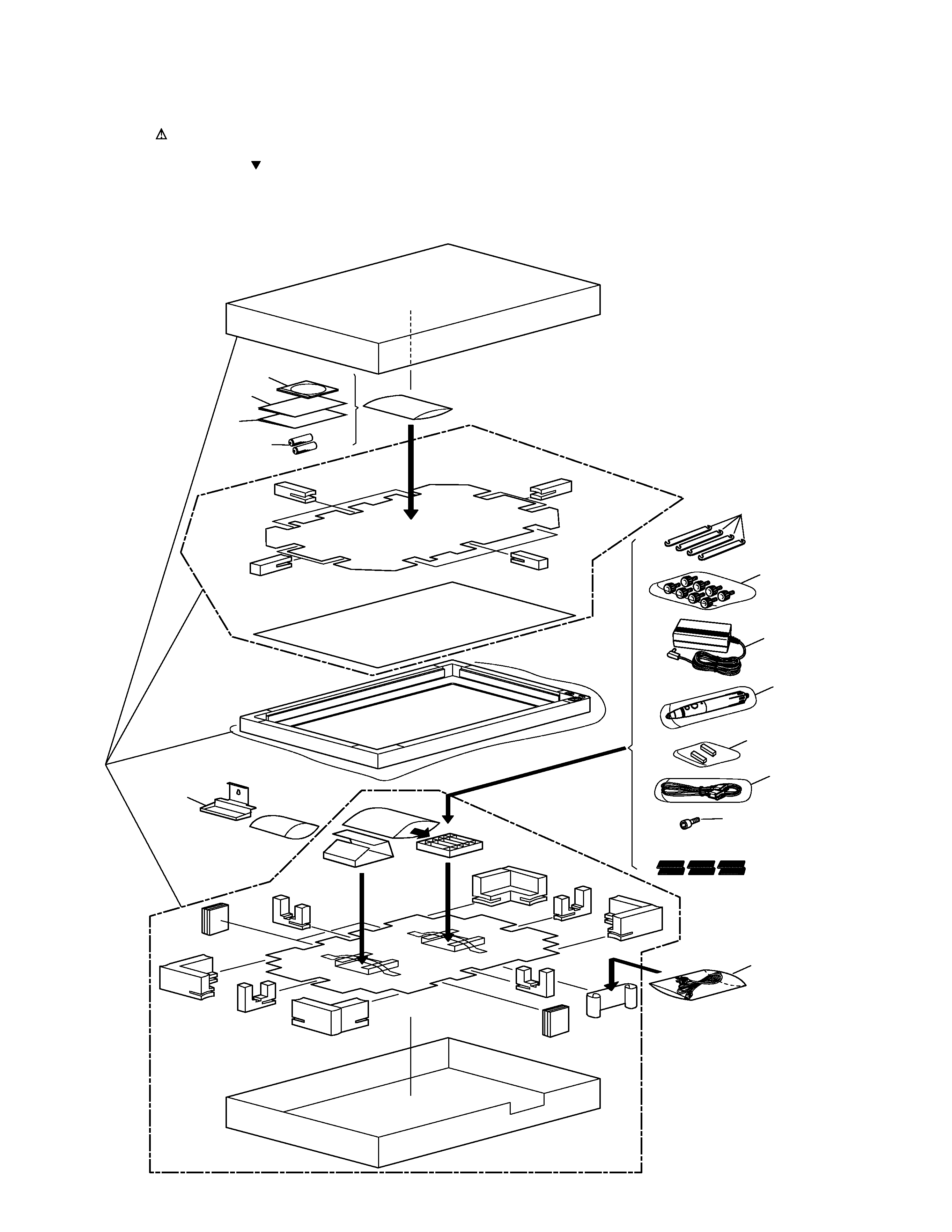
2.1 HAND WRITING DEVICE [ PDK-50HW2 ]
2. EXPLODED VIEWS AND PARTS LIST
NOTES:
· Parts marked by "NSP" are generally unavailable because they are not in our Master Spare Parts List.
· The mark found on some component parts indicates the importance of the safety factor of the part.
Therefore, when replacing, be sure to use parts of identical designation.
· Screws adjacent to mark on the product are used for disassembly.
2.1.1 PACKING

5
PDK-50HW2
PACKING PARTS LIST
1
Knurled Fingerbolts
AZB1443
2
· · · · ·
3
RS-232C Cable
AZD1110
4
AC Power Cord(for US)
AZD1114
4
AC Power Cord(for Europe)
ADG1173
5
Packing Set
AZH1146
6
Pen Stand
AZN2485
7
Mounting Bar
AZN2486
8
Operating Instractions
AZR1053
(Japanese, English, French, German)
9
Driver Software
AZR1054
10
AC Adapter
AZX1057
11
Pen
AZX1058
12
Allen Bolt
SMZ80H200FNI
13
Replacement Tip
AZE1119
14
Operating Instractions
AZR1057
(Italian, Dutch, Spanish)
Mark No.
Description
Part No.