ORDER NO.
PIONEER CORPORATION 4-1, Meguro 1-chome, Meguro-ku, Tokyo 153-8654, Japan
PIONEER ELECTRONICS (USA) INC. P.O. Box 1760, Long Beach, CA 90801-1760, U.S.A.
PIONEER EUROPE NV Haven 1087, Keetberglaan 1, 9120 Melsele, Belgium
PIONEER ELECTRONICS ASIACENTRE PTE. LTD. 253 Alexandra Road, #04-01, Singapore 159936
PIONEER CORPORATION 2005
ARP3274
T ZZR JULY 2005 Printed in Japan
PDA-H05
TYV/EW
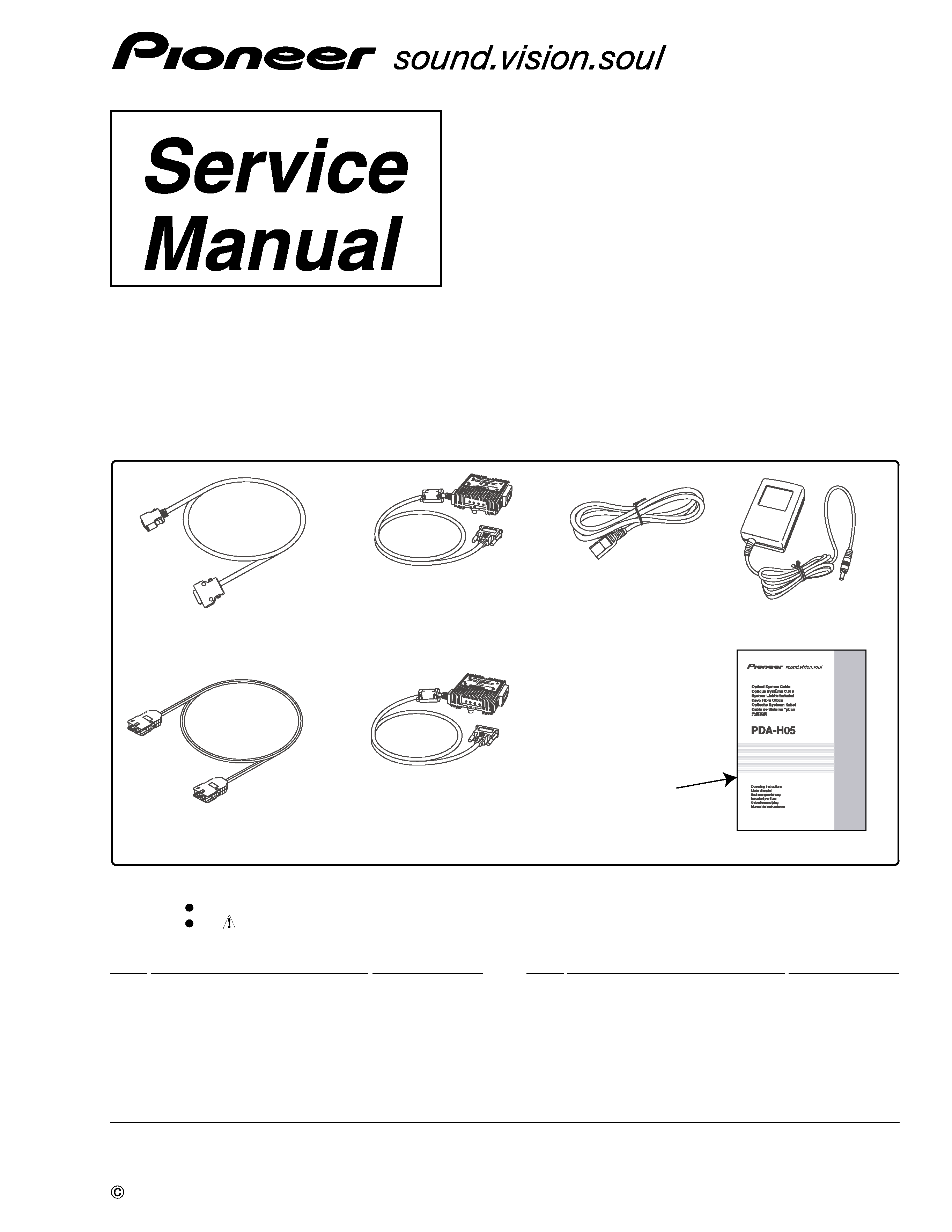
OPTICAL SYSTEM CABLE
[AXY1123]
[AXY1125]
[AXY1124]
[ADY1090]
[ADF1030]
[AZR1102]
[ADG1214 (for EU model)]
Repeater Boxes
(Transmitter Box:
×1)
Repeater Boxes
(Receiver Box:
×1)
AC/DC power adapter:
×2
Operating instructions:
×1
WEEE Caution Card :
×1
[ARM7099]
System cable
(Connector: Black/Silver) :
×2
Optical cable:
×1
AC power cord: x2
PARTS LIST
Mark No.
Description
Part No.
Mark No.
Description
Part No.
7 Checking the Enclosed Parts
MDR Cable (System Cable)
ADF1030
>
AC Power Cord (for EU model)
ADG1214
Optical Cable
ADY1090
>
Transmitter
AXY1123
>
Receiver
AXY1124
>
AC/DC Power Adapter
AXY1125
Cleaning Kit
AZE1141
Packing Set
AZH1178
Operating Instructions
AZR1102
(Japanese / English / French / German
/ Italian/Dutch / Spanish / Simp-Chinese)
WEEE Caution Card
ARM7099
Parts marked by "NSP" are generally unavailable because they are not in our Master Spare Parts List.
The
mark found on some component parts indicates the importance of the safety factor of the part.
Therefore, when replacing, be sure to use parts of identical designation.
NOTES:
2
1
23
4
12
3
4
C
D
F
A
B
E
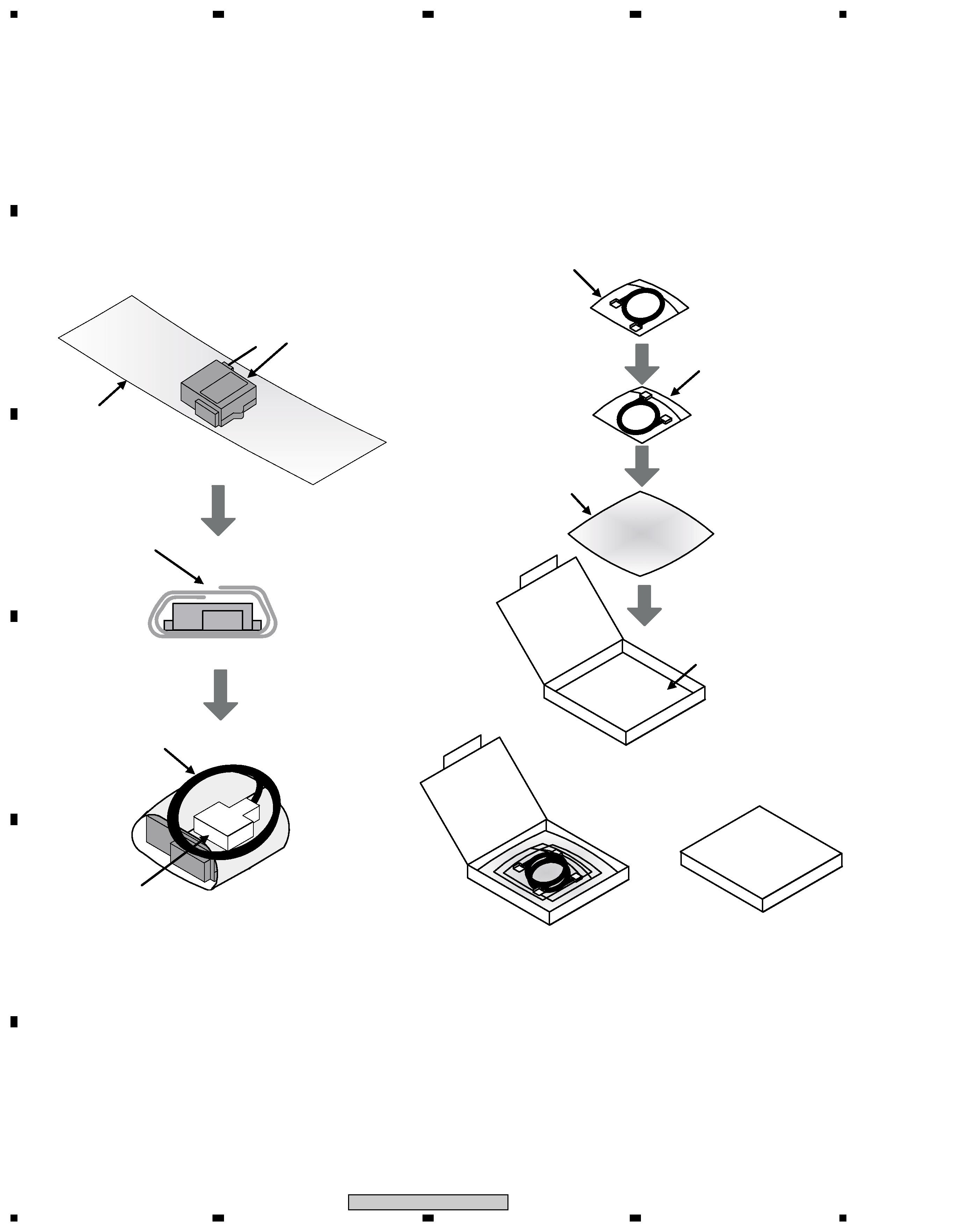
PDA-H05
PACKING
Transmitter Box
[AXY1123]
Receiver Box
[AXY1124]
Sheet
Sheet
double winding
& tape stop
[Transmitter Box,
Receiver Box]
[Cable's box]
DVI cable
Wind it up twice
MDR cable
[ADF1030]
Optical cable
[ADY1090]
of bag going in
MDR cable
[ADF1030]
Cable's box
DVI connector
Mount with a guard cap
3
1
23
4
1
2
3
4
C
D
F
A
B
E
PDA-H05
Receiv
er
Bo
x[AXY1124]
A
C/DC
po
w
er
adapter
[AXY1125]
T
ransmitter
Bo
x
[AXY1123]
Cab
le's
bo
x
Car
ton
bo
x
Slee
v
e
Caution
Card
[ARM7099]
A
C
po
w
er
cord
Input
por
t
(notch)
A
C
po
w
er
cord
Input
por
t
(notch)
A
C
po
w
er
cord
Input
por
t
(notch)
A
C
po
w
er
cord
ADG1214(f
or
EU
model)
A
C/DC
po
w
e
r
adapter
[AXY1125]
W
type
spacer
[Car
ton
bo
x]
Oper
ating
instr
uctions
[AZR1102]
tape
stop
tape
stop
4
1
23
4
12
3
4
C
D
F
A
B
E
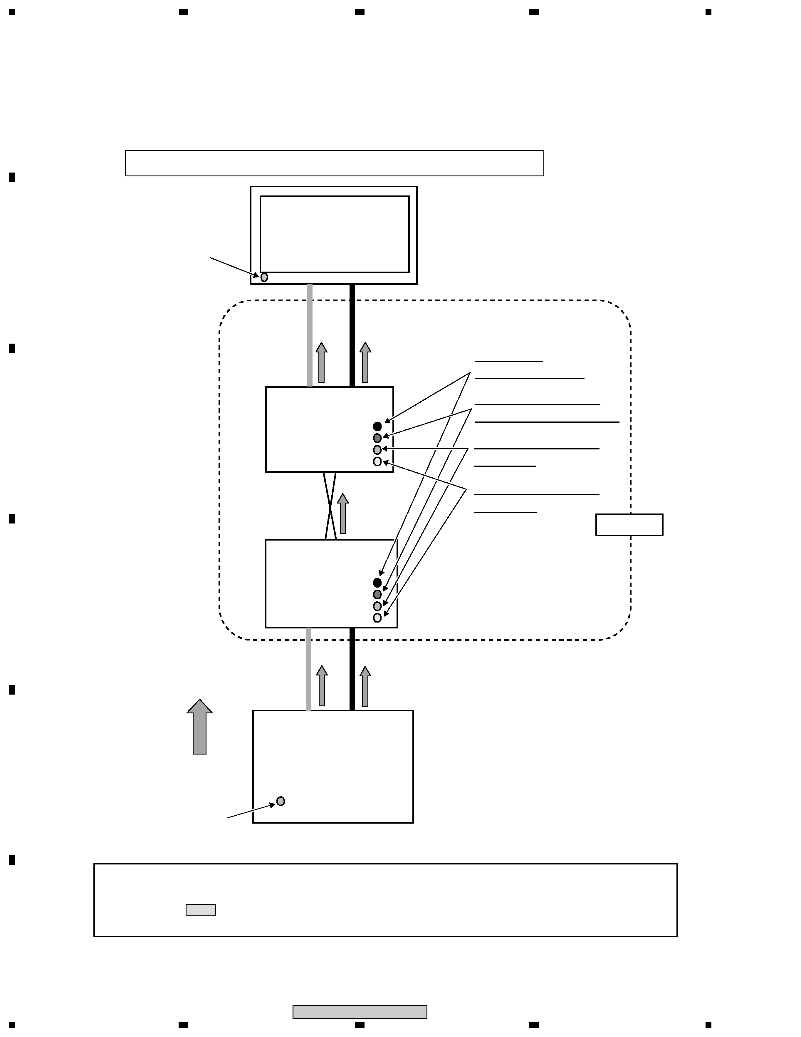
PDA-H05
Panel power indicator
(lights green)
The indicators light to show the signal flow and proper operation of each device.
Signal flow
White/DVI
Black/MDR
White/DVI
Panel
Receiver
(repeater box)
Transmitter
(repeater box)
Media receiver
Optical cable
Power (PWR)
Indicator lights green
Rising low speed optical
reception (OSD) lights green
Laser drive control (OSE)
lights green
Laser drive status (ACT)
lights green
V
ideo
Signal
Audio
Signal
Control
Signal
V
ideo
Signal
Audio
Signal
Control
Signal
Audio
Signal
Control
Signal
V
ideo
Signal
PDA-H05
Media receiver
power indicator
(lights green)
When there is no picture and sound or the set's power does not come on.
· Connection the PDA-H05 with the panel and media receiver
· The following page shows the process for identifying problems with the PDA-H05.
First, use the standard system cable to check whether there are any problems in the operation of the plasma display.
· Shaded areas(
) indicate that service from Pioneer is required.
Please contact Pioneer's Customer Support Center.
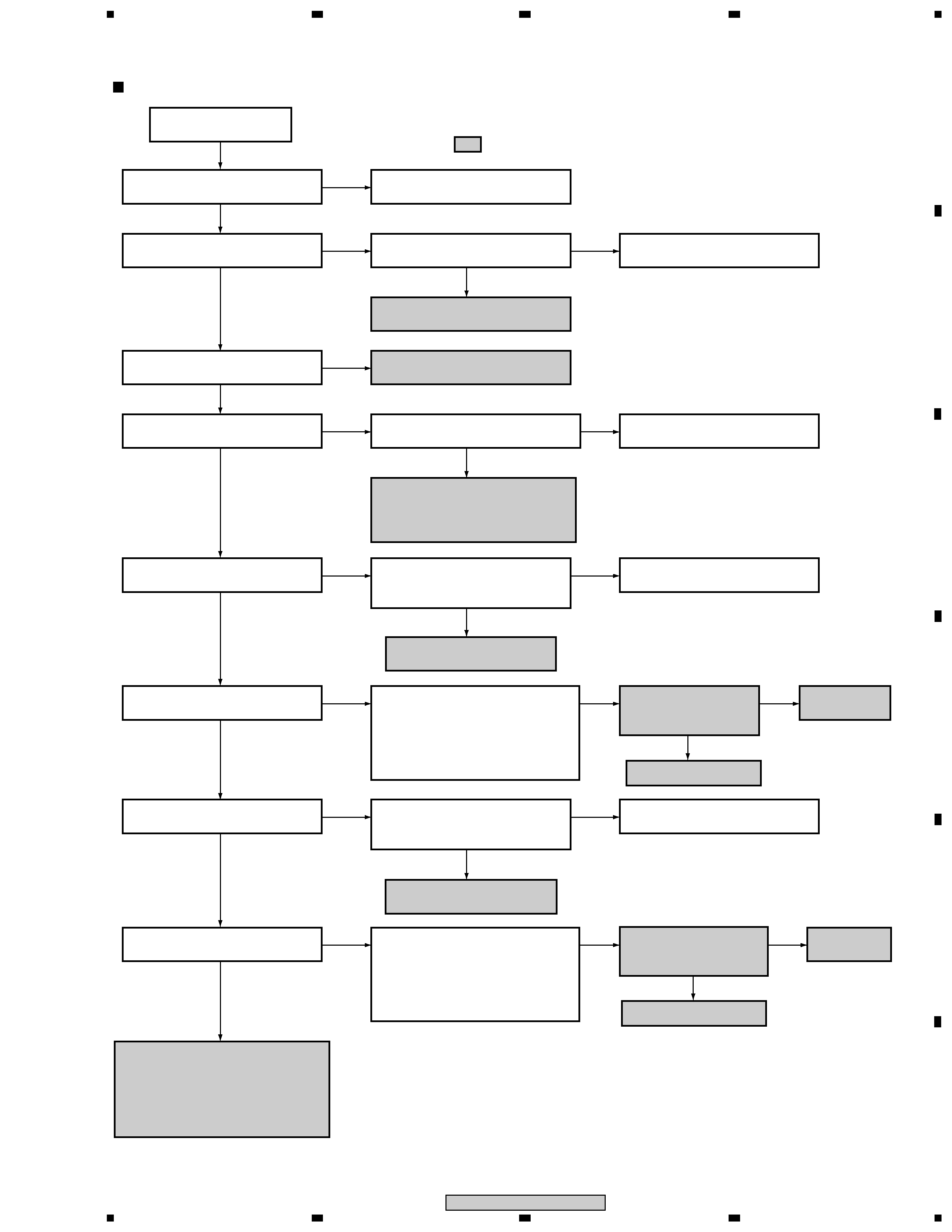
Troubleshooting
5
1
23
4
1
2
3
4
C
D
F
A
B
E
PDA-H05
No image and no sound
No image and no sound
Is the transmitter connected to the
MR and the receiver to the panel?
Connect the transmitter to the MR
and the receiver to the panel.
No
Yes
Yes
Is the ACT LED of the transmitter
lit?
Replace the transmitter.
No
Yes
Are the PWR (power) LEDs of the
transmitter and receiver lit?
Are the AC adaptors connected to
the transmitter and receiver?
Replace the AC adaptors.
No
Connect the AC adaptors.
No
Yes
Yes
Is the OSE LED of the transmitter
lit?
Are the DVI and MDR cables
properly connected between the
transmitter and the MR?
Replace the transmitter.
No
Connect the DVI and MDR cables.
No
Yes
Yes
Is the OSE LED of the receiver lit?
Are the DVI and MDR cables
properly connected between the
receiver and the panel?
Replace the receiver.
No
Connect the DVI and MDR cables.
No
Yes
Yes
Is the OSD LED of the receiver lit?
Using the dedicated cleaning kit
,
clean the ferrule (tip of the optical
cable) and inside the repeater box
of the receiving side. Connect the
cables again and check if an image
is displayed and the sound is output.
Replace the receiver.
No
After replacing the
receiver, is the OSD
LED of the receiver lit?
Replace the
optical cable.
No
No
Yes
Yes
Replace the transmitter.
Yes
Is the OSD LED of the transmitter
lit?
Connect the MR and the panel
directly, using the 3-meter cable
and check if an image is displayed
and the sound is output. If both are
output, replacement of both the
transmitter and receiver is required.
Using the dedicated cleaning kit
,
clean the ferrule (tip of the optical
cable) and inside the repeater box
of the receiving side. Connect the
cables again and check if an image
is displayed and the sound is output.
No
After replacing the
transmitter, is the OSD
LED of the transmitter lit?
Replace the
optical cable.
No
No
Yes
Is the ACT LED of the receiver lit?
Is the DVI cable properly connected
between the receiver and the panel?
No
Connect the DVI cable.
No
Yes
Yes
Note:
· MR: Media Receiver
· Transmitter, receiver: Transmitting- or receiving-side repeater box, respectively
·
: Repair for servicing
Replace the DVI cable connected
to the receiver. If no image is
displayed after replacing the cable,
replace the receiver.
: Cleaning kit AZE1141