SERVICE MANUAL
COPYRIGHT © 2004 Victor Company of Japan, Limited
No.52090C
2004/6
PDP COLOUR TELEVISION
52090
2003
03
PD-42D30ES
PD-42D30ES/A
TABLE OF CONTENTS
1.
CONFIRMING THE MODEL NAME, SERIAL NUMBER, ID NUMBER, AND CODE NUMBER
2.
MAIN PARTS LOCATION
3.
INSPECTION OF COMPONENTS ON THE PW BOARD
4.
DISASSEMBLY PROCEDURE
5.
CONFIRMING REFERENCE VOLTAGE
6.
ADJUSTMENTS
7.
PARTS LIST
2
2
3
6
8
9
10
BASIC CHASSIS
MK
Supplementary
These models corresponded to the printed circuit board exchange in the PDP panel.
Therefore, this service manual describes only the information relevant to it.
For details other than those described in this manual, please refer to the PD-42D30ES service
manual (No.52090 2003/03), PD-42D30ES/A service manual (No.52090B 2003/06).
NOTES AT THE TIME OF PW BOARD EXCHANGE
It will become the cause of failure if dust adheres to the inside of a connector, or a flat wire and
a point-of-contact part.
When the PW board is exchanged, be careful of the dust and dirt of the inside of a connector, or
a flat wire and a point-of-contact part enough.
2(No.52090C)
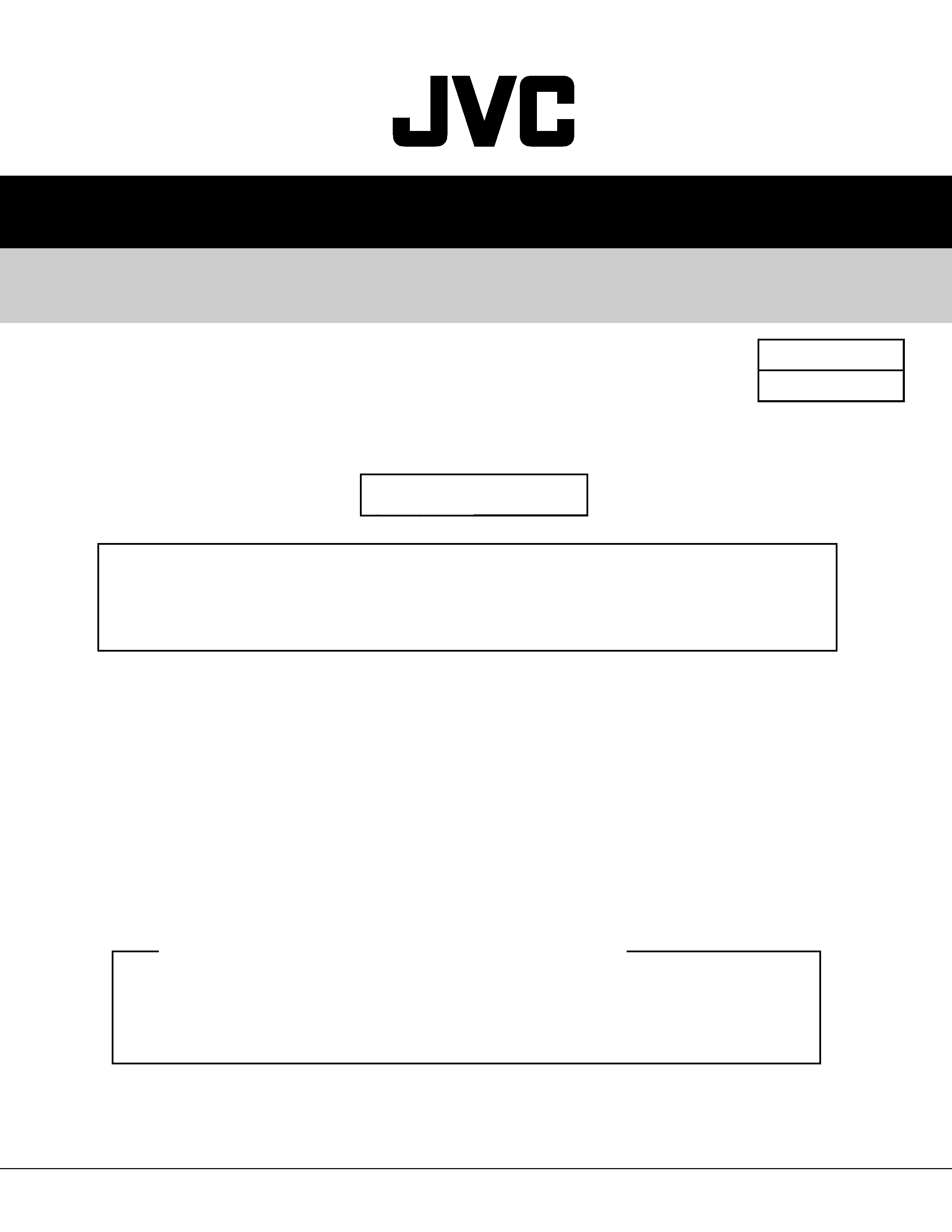
CONFIRMING MODEL NAME, SERIAL NUMBER, ID NUMBER AND CODE
NUMBER
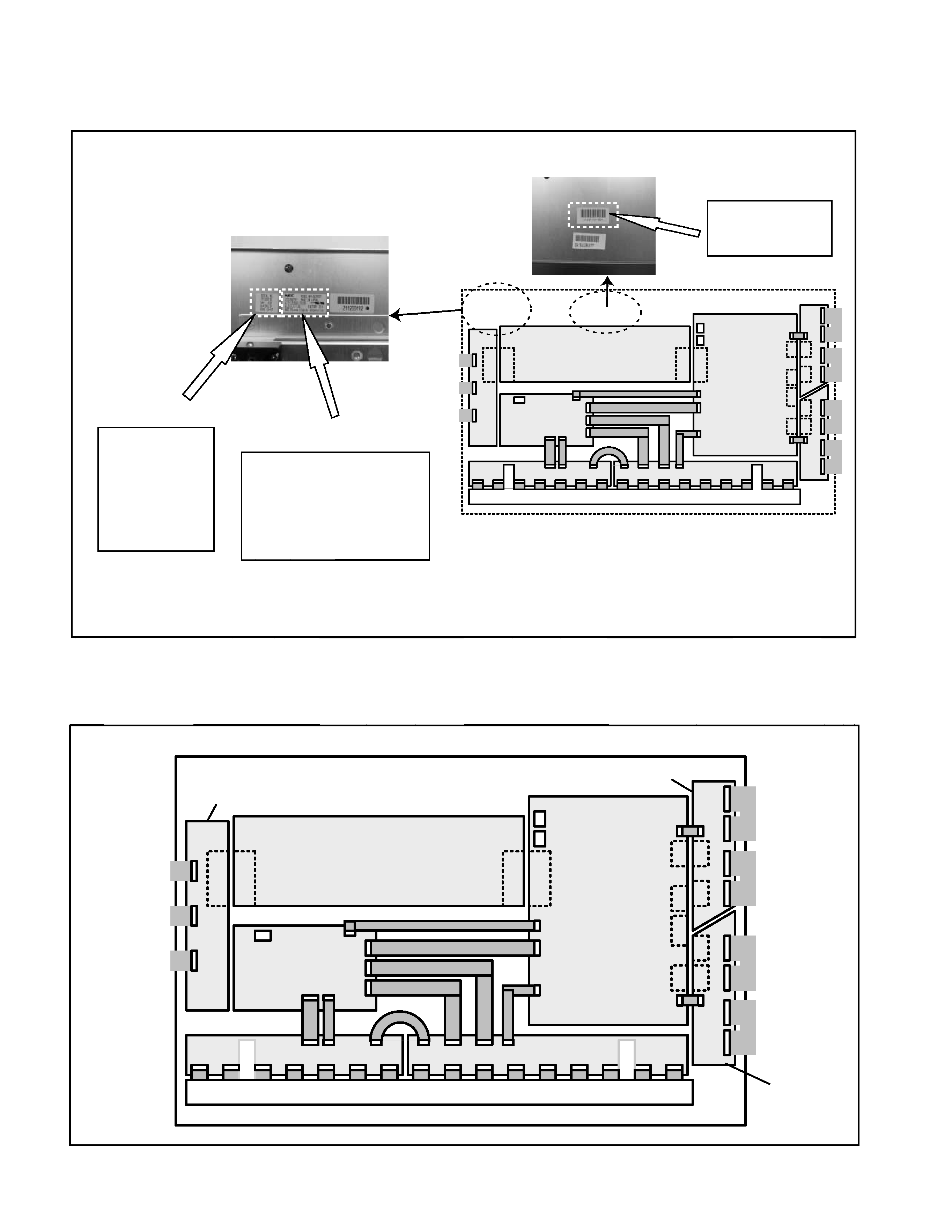
MAIN PARTS LOCATION
SERIAL NO.
211200192
Vd=65V
Vs=190.1V
CODE AA-01
CODE : AA
212211041621
PANEL ID No.
Model name and serial No.
For example
For example
Model : NP42D2MF01AA
Serial No. : 211200192 (9 figures)
NEC NP42D2MF01AA
211200192
Voltage and CODE No.
*******************
*******************
*******************
(12 figures)
NOTE : The panel's ID number is used when you reference the characteristic voltage value of the panel
on web site.
SCAN RELAY PWB(upper)
SCAN RELAY
PWB(lower)
Flexible cable
Scan-side A
COMMON PWB
COMMON BRANCH PWB
DIGITAL PWB
Heat-sink
SIGNAL RELAY PWB(left)
SIGNAL RELAY PWB(right)
HIGH VOLTAGE
PWB
Flexible cable
Scan-side B
Flexible cable
Scan-side C
Flexible cable
Scan-side D
Flexible cable
Common-side A
Flexible cable
Common-side B
Flexible cable
Common-side C
A
B
C
D
E
F
G
H
I
J
K
L
M
N
O
P
(No.52090C)3
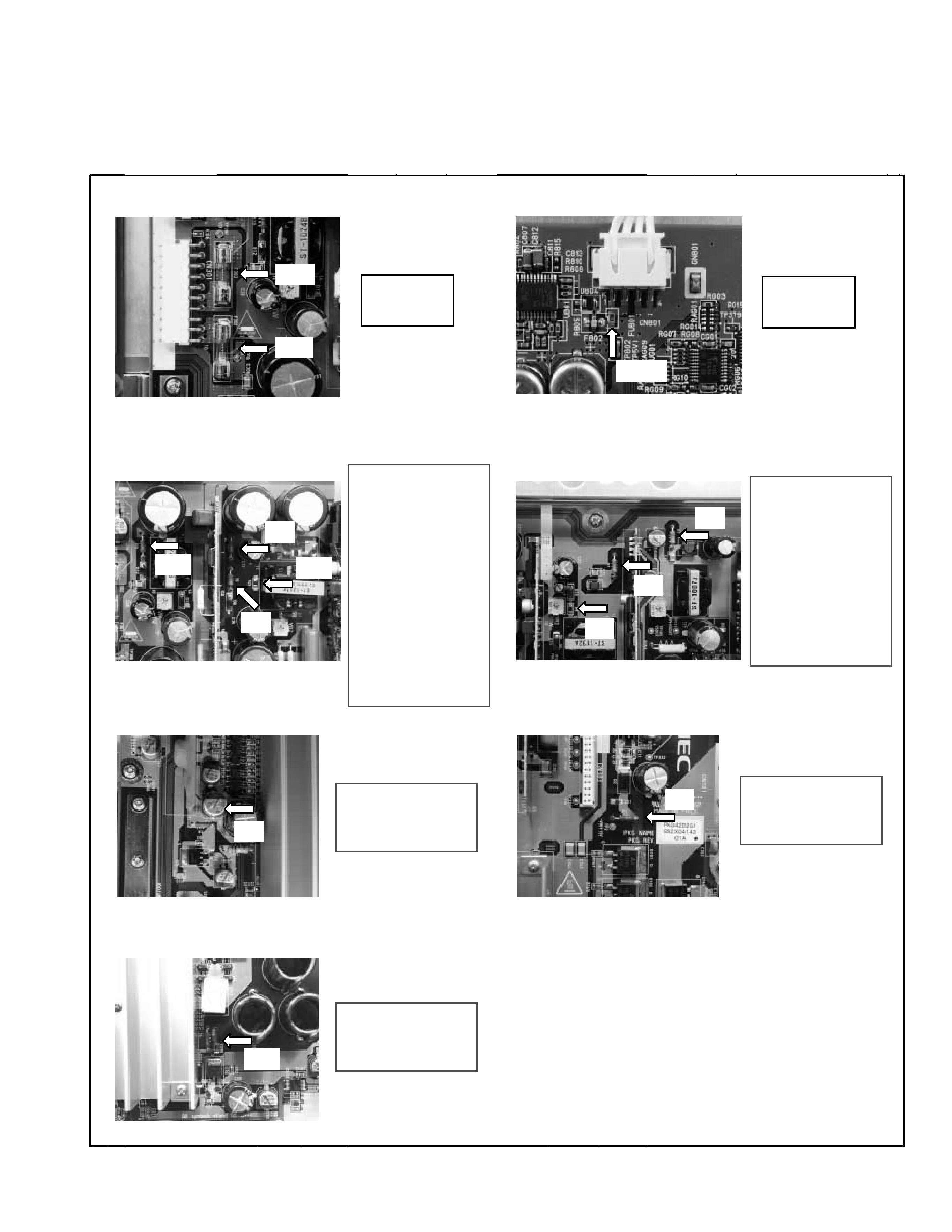
1. Inspection of fuses
Measure the resistance of each fuse with a circuit tester, and check OK or NG.
INSPECTION OF COMPONENTS ON THE PW BOARD
Diagnose the PW board in PDP unit by checking defects based on the following items.
1.1 Glass fuses (F301, F302) on the HIGH VOLTAGE PWB
1.2 Chip fuse (FU801) on the DIGITAL PWB
OK: Short
NG: Open
OK: Short
NG: Open
R10
OK: Approx. 2.2
NG: Open
R4
OK: Approx. 2.2
NG: Open
R6
OK: Approx. 2.2
NG: Open
R20
OK: Approx. 10
NG: Open
R7
OK: Approx. 2.2
NG: Open
R2
OK: Approx. 2.2
NG: Open
R1
OK: Approx. 2.2
NG: Open
R90
OK: Approx. 2.2
NG: Open
R3
OK: Approx. 2.2
NG: Open
R9
OK: Approx. 10
NG: Open
1.3 Fuse resistances (R10, R4, R6) and chip fuse (R20)
on the HIGH VOLTAGE PWB
1.4 Fuse resistances (R7, R3) and chip fuse (R9)
on the HIGH VOLTAGE PWB
1.6 Fuse resistance (R2) on the HIGH VOLTAGE PWB
1.5 Fuse resistance (R1) on the HIGH VOLTAGE PWB
1.7 Fuse resistance (R90) on the HIGH VOLTAGE PWB
R4
R20
R10
R3
R6
R7
R9
R2
R90
R1
301
302
801
4(No.52090C)
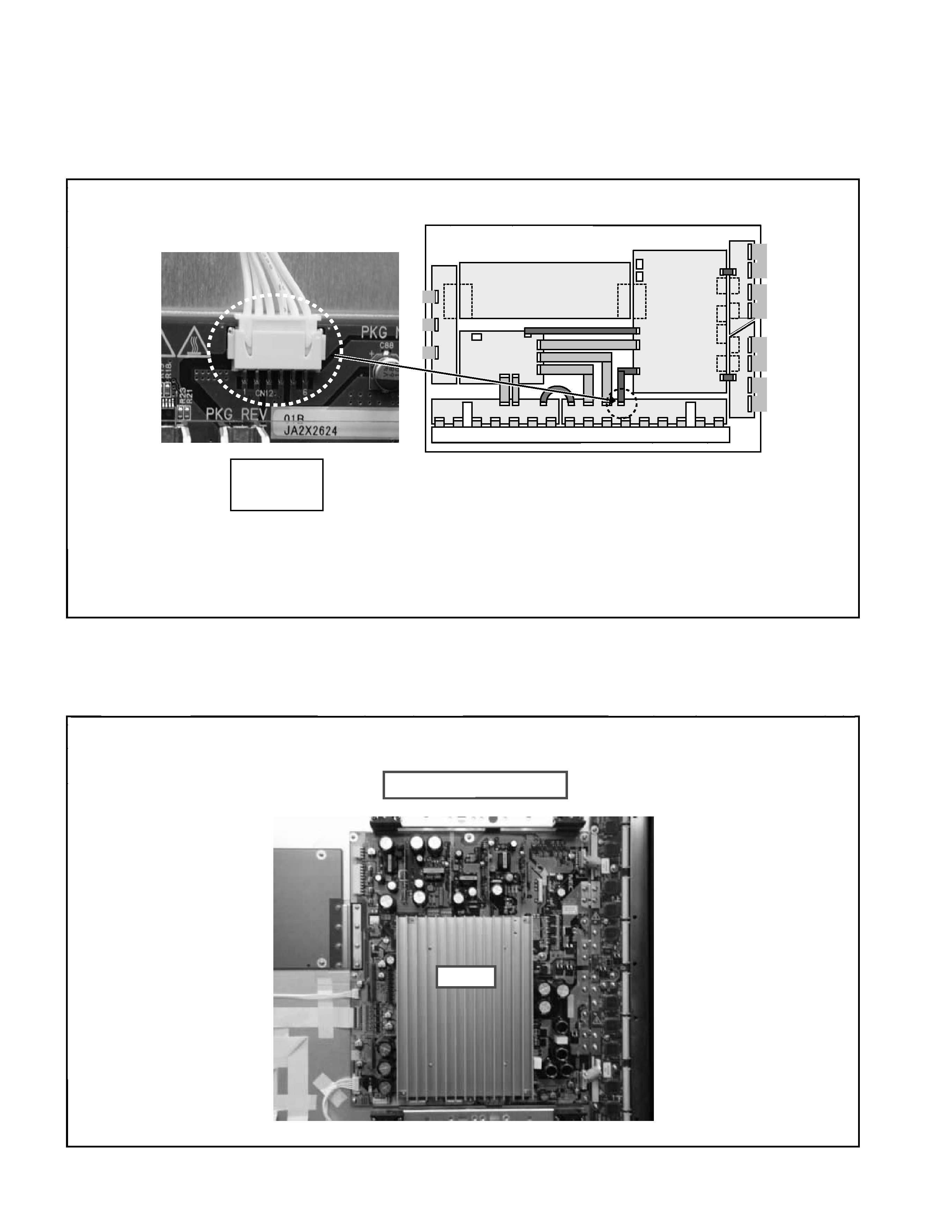
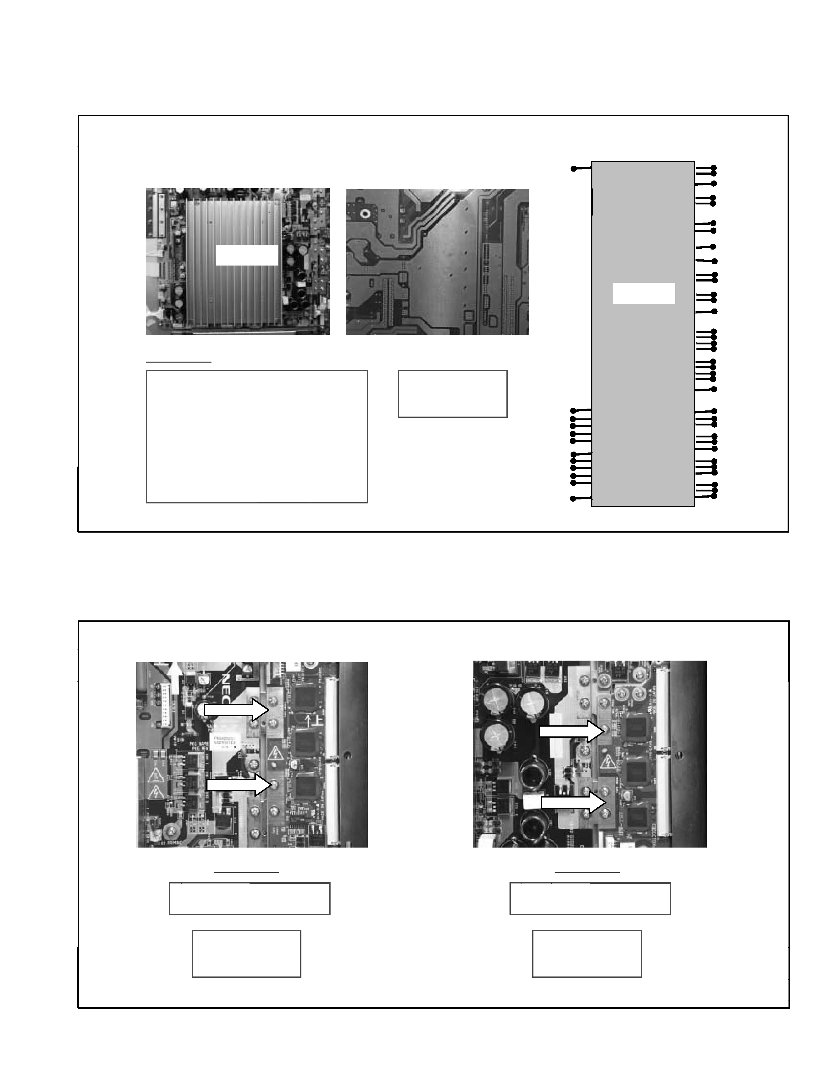
2. Inspection of data ICs
According to the following procedures, measure with a circuit tester and check OK or NG.
3. Inspection of power IC
According to the following procedures, measure with a circuit tester and check OK or NG.
HIGHT VOLTAGE PWB
PH2203F
The allocation of power IC to be checked is shown below.
Check the pin 1 or pin 2 of the connector [CN12] on the SIGNAL RELAY PWB (right).
OK: Open
NG: Short
Detach the connector [CN12] on the SIGNAL RELAY PWB (right) and check the conduction between the pin 1 (or
pin 2) and the ground.
In case of "short", one of the data ICs connecting the SIGNAL RELAY PWB may be defective, and you should check
whether there is any trace of damage on the data IC's surface after removing the heat-sink on the data IC.
(No.52090C)5
4. Inspection of scan IC drivers
According to the following procedures, measure with a circuit tester and check OK or NG.
Turn over the board and check each point of power IC as shown below.
3.1 PH2203F on the HIGH VOLTAGE PWB
Between NEGA - POSI
L
F
PH2203F
G
H
M
E
D
C
B
A
I
K
J
N
O
P
Q
R
S
T
U
PH2203F
A
B
C
D
E
F
G
H
I
J
K
L
M
N
O
P
Q
S
R
T
U
Check point
OK: Over 1k
NG: Short
Between
A - B
A - U
B - C
B - E
B - M
B - N
Between
C - U
F - U
G - H
H - J
I - J
J - K
Between
J - O
L - M
P - T
Q - T
OK: Over 1k
NG: Short
Check point
Between NEGA - POSI
OK: Over 1k
NG: Short
Check point
4.1 Scan IC driver on the SCAN RELAY PWB (upper right) 4.2 Scan IC driver on the SCAN RELAY PWB (lower right)
NEGA 1
POSI 1
NEGA 2
POSI 2