ORDER NO.
PIONEER CORPORATION 4-1, Meguro 1-chome, Meguro-ku, Tokyo 153-8654, Japan
PIONEER ELECTRONICS SERVICE, INC. P.O. Box 1760, Long Beach, CA 90801-1760, U.S.A.
PIONEER EUROPE NV Haven 1087, Keetberglaan 1, 9120 Melsele, Belgium
PIONEER ELECTRONICS ASIACENTRE PTE. LTD. 253 Alexandra Road, #04-01, Singapore 159936
PIONEER CORPORATION 2000
c
THIS MANUAL IS APPLICABLE TO THE FOLLOWING MODEL(S) AND TYPE(S).
M-LA21
RRV2393
T IZK OCT. 2000 Printed in Japan
STEREO POWER AMPLIFIER
1. SAFETY INFORMATION ....................................... 2
2. EXPLODED VIEWS AND PARTS LIST ................. 3
3. SCHEMATIC DIAGRAM .......................................... 6
4. PCB CONNECTION DIAGRAM ........................... 12
5. PCB PARTS LIST ................................................ 18
6. ADJUSTMENT ..................................................... 19
CONTENTS
7. GENERAL INFORMATION ................................ 20
7.1 DIAGNOSIS .................................................. 20
7.1.1 SINGLE OPERATION METHOD ......... 20
7.1.2 DISASSEMBLY .................................... 21
8. PANEL FACILITIES AND SPECIFICATIONS .... 23
LA21
STEREO POWER AMPLIFIER
DINAMIC
-- OFF _ ON
DYNAMIC MODE
HIGH EFFICIENT
AMPLIFIER
POWER OUTPUT
Component
Model
Service manual
Remarks
COMPACT MINI COMPONENT
X-LA21
RRV2370
STEREO CD TUNER
XC-LA21
RRV2392
STEREO POWER AMPLIFIER
M-LA21
RRV2393
This manual.
SPEAKER SYSTEM
S-LA21
RRV2394
¶ System component Table
¶ This product is a system(s) component.
This product does not function properly independently ; to avoid malfunctions, be
sure to connect it to the prescribed system component(s), otherwise damage may
result.
¶ Please connect it to the STEREO CD TUNER XC-LA21, for operation inspection.
Type
Model
Power Requirement
The voltage can be converted by
M-LA21
the following method.
DBDXCN
AC110-127V / 220-230V / 240V
With the Voltage Selector
DDXCN/AR
AC110-127V / 220-230V / 240V
With the Voltage Selector
2
M-LA21
1. SAFETY INFORMATION
This service manual is intended for qualified service technicians ; it is not meant for the casual do-it-
yourselfer. Qualified technicians have the necessary test equipment and tools, and have been trained
to properly and safely repair complex products such as those covered by this manual.
Improperly performed repairs can adversely affect the safety and reliability of the product and may
void the warranty. If you are not qualified to perform the repair of this product properly and safely, you
should not risk trying to do so and refer the repair to a qualified service technician.
WARNING
This product contains lead in solder and certain electrical parts contain chemicals which are known to the state of California to cause
cancer, birth defects or other reproductive harm.
Health & Safety Code Section 25249.6 Proposition 65
NOTICE
(FOR CANADIAN MODEL ONLY)
Fuse symbols
(fast operating fuse) and/or
(slow operating fuse) on PCB indicate that replacement parts must
be of identical designation.
REMARQUE
(POUR MODÈLE CANADIEN SEULEMENT)
Les symboles de fusible
(fusible de type rapide) et/ou
(fusible de type lent) sur CCI indiquent que les pièces
de remplacement doivent avoir la même désignation.
ANY MEASUREMENTS NOT WITHIN THE LIMITS
OUTLINED ABOVE ARE INDICATIVE OF A POTENTIAL
SHOCK HAZARD AND MUST BE CORRECTED BEFORE
RETURNING THE APPLIANCE TO THE CUSTOMER.
2. PRODUCT SAFETY NOTICE
Many electrical and mechanical parts in the appliance
have special safety related characteristics. These are
often not evident from visual inspection nor the protection
afforded by them necessarily can be obtained by using
replacement components rated for voltage, wattage, etc.
Replacement parts which have these special safety
characteristics are identified in this Service Manual.
Electrical components having such features are identified
by marking with a
on the schematics and on the parts list
in this Service Manual.
The use of a substitute replacement component which does
not have the same safety characteristics as the PIONEER
recommended replacement one, shown in the parts list in
this Service Manual, may create shock, fire, or other hazards.
Product Safety is continuously under review and new
instructions are issued from time to time. For the latest
information, always consult the current PIONEER Service
Manual. A subscription to, or additional copies of, PIONEER
Service Manual may be obtained at a nominal charge from
PIONEER.
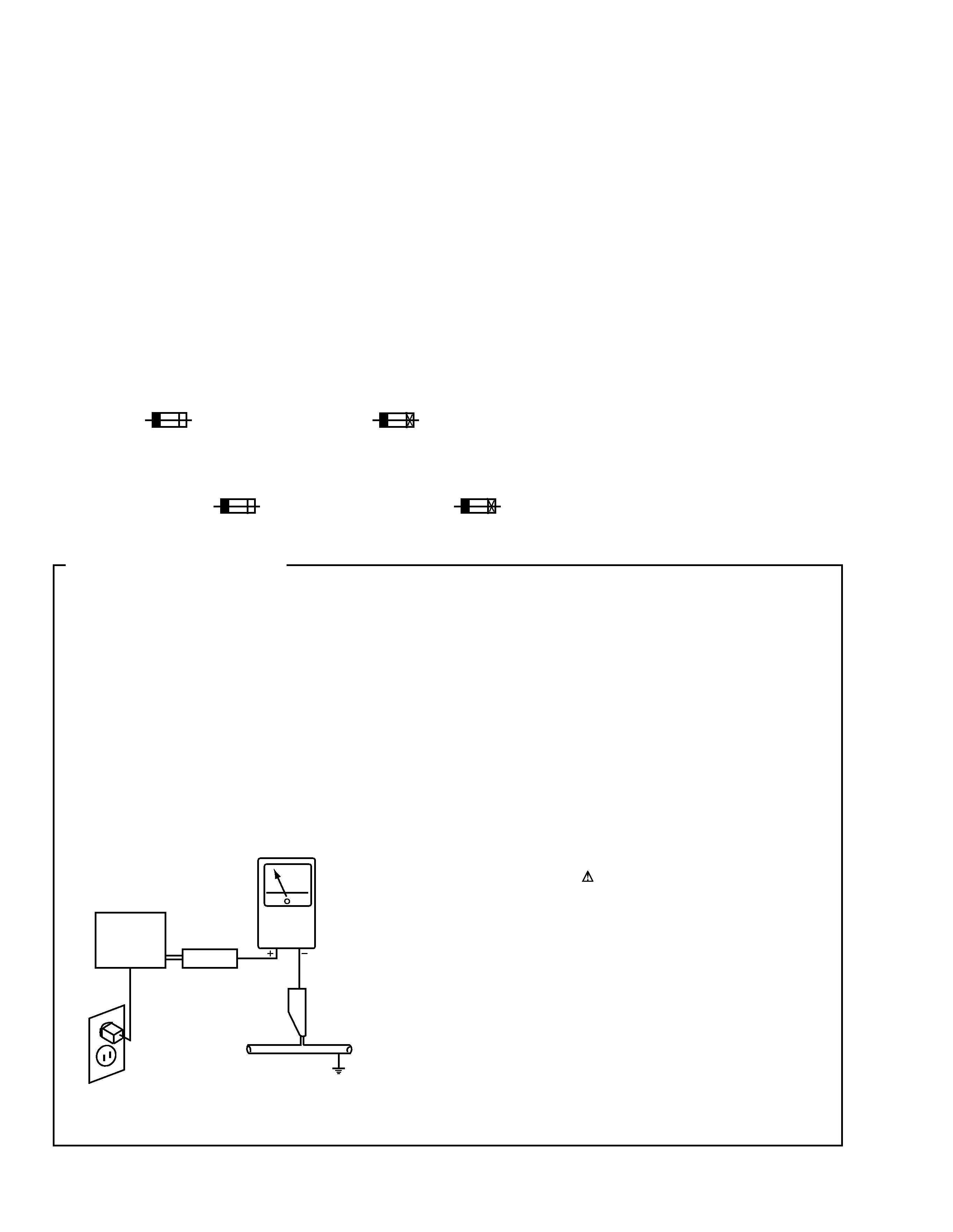
1. SAFETY PRECAUTIONS
The following check should be performed for the
continued protection of the customer and service
technician.
LEAKAGE CURRENT CHECK
Measure leakage current to a known earth ground (water
pipe, conduit, etc.) by connecting a leakage current tester
such as Simpson Model 229-2 or equivalent between the
earth ground and all exposed metal parts of the appliance
(input/output terminals, screwheads, metal overlays, control
shaft, etc.). Plug the AC line cord of the appliance directly
into a 120V AC 60Hz outlet and turn the AC power switch
on. Any current measured must not exceed 0.5mA.
(FOR USA MODEL ONLY)
Leakage
current
tester
Reading should
not be above
0.5mA
Device
under
test
Test all
exposed metal
surfaces
Also test with
plug reversed
(Using AC adapter
plug as required)
Earth
ground
AC Leakage Test
3
M-LA21
2. EXPLODED VIEWS AND PARTS LIST
NOTES:
· Parts marked by "NSP" are generally unavailable because they are not in our Master Spare Parts List.
· The mark found on some component parts indicates the importance of the safety factor of the part.
Therefore, when replacing, be sure to use parts of identical designation.
· Screws adjacent to mark on the product are used for disassembly.
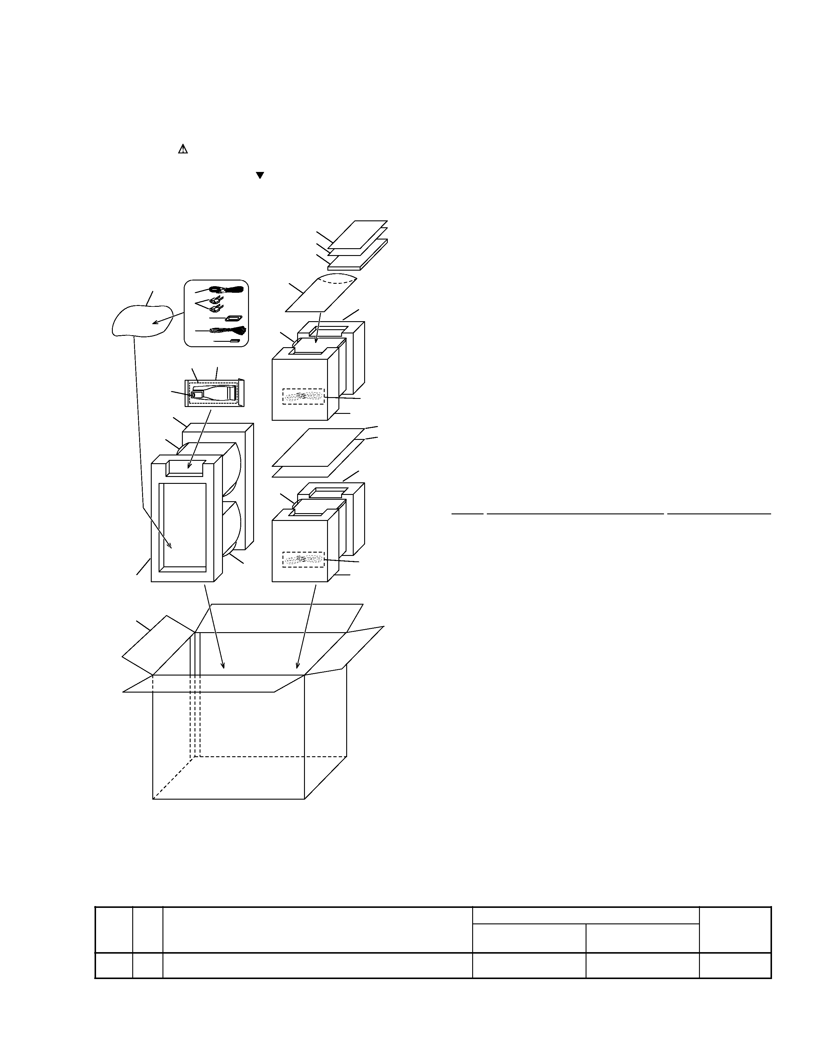
2.1 PACKING (X-LA21)
SYSTEM
SPEAKER
REAR
XC-LA21
REAR
M-LA21
FRONT
FRONT
FRONT
FRONT
TOP SIDE
TOP SIDE
13
3
1
5
14
7
4
11
17
15
16
19
20
DDXCN/AR Only
9(2/2)
10
10
9(1/2)
8(2/2)
12
8(1/2)
18
18
11
8(2/2)
12
12
8(1/2)
6
2
(1) PACKING PARTS LIST
Mark No.
Description
Part No.
1
AM Loop Antenna
ANT-PMT1E-AL
2
Remote Control Unit
AXD7289
3
RCA Audio Cable
122003220100
NSP
4
`AAA' Size R03 Batteries
130115004000
5
FM Wire Antenna
132030001001
6
Power-cord Plug Conversion Adaptor
138011722000
7
Battery Door
500RC4603070
8
Polyform Unit
800PMT190001
9
Polyfoam (Speaker)
800PMT390000
10
Poly Foam Sheet (C) SP
801999000002
11
Polythenefoam Sheet
801999000005
NSP
12
PE Polybag (AC Cord)
805032115000
NSP
13
PE Polybag (Remocon)
805035105000
NSP
14
PE Polybag (Antenna)
805070100000
NSP
15
PE Polybag (I Book)
805085140000
16
Operating Instructions
811PMT391011
(English/Spanish/Chinese)
17
Carton
See Contrast table (2)
18
Corrugate Card
815001405213
19
Additional Sheet
810PMT395010
20
Correction Sheet
See Contrast table (2)
(2) CONTRAST TABLE
X-LA21/DBDXCN and DDXCN/AR are constructed the same except for the following :
Part No.
Mark No.
Symbol and Description
X-LA21
X-LA21
Remarks
/DBDXCN
/DDXCN/AR
17
Carton
813PMT393020
813PMT393010
20
Correction Sheet
Not used
810PMT395020
4
M-LA21
22
15
18
2
51
16
3
29
49
42
49
53
52
52
47
48
52
52
53
20
53
50
53
53
53
52
53
31
53
53
53
34
28
7
5
6
52
53
10
54
54
53
53
50
12
19
45
13
43
1
32
33(
×3)
49
40
9
4
53
53
53
53
53
53
53
53
52
52
30
53
35
17
14
25
36
26
38
37
36
39
55
56
DDXCN/AR
Only
DDXCN/AR
Only
57
44
46
44
52
27
B
C
C
E
G
B
D
D
A
F
F
H
G
A
E
H
11
23
24
21
D
B
C
A
F
E
G
DBDXCN
Only
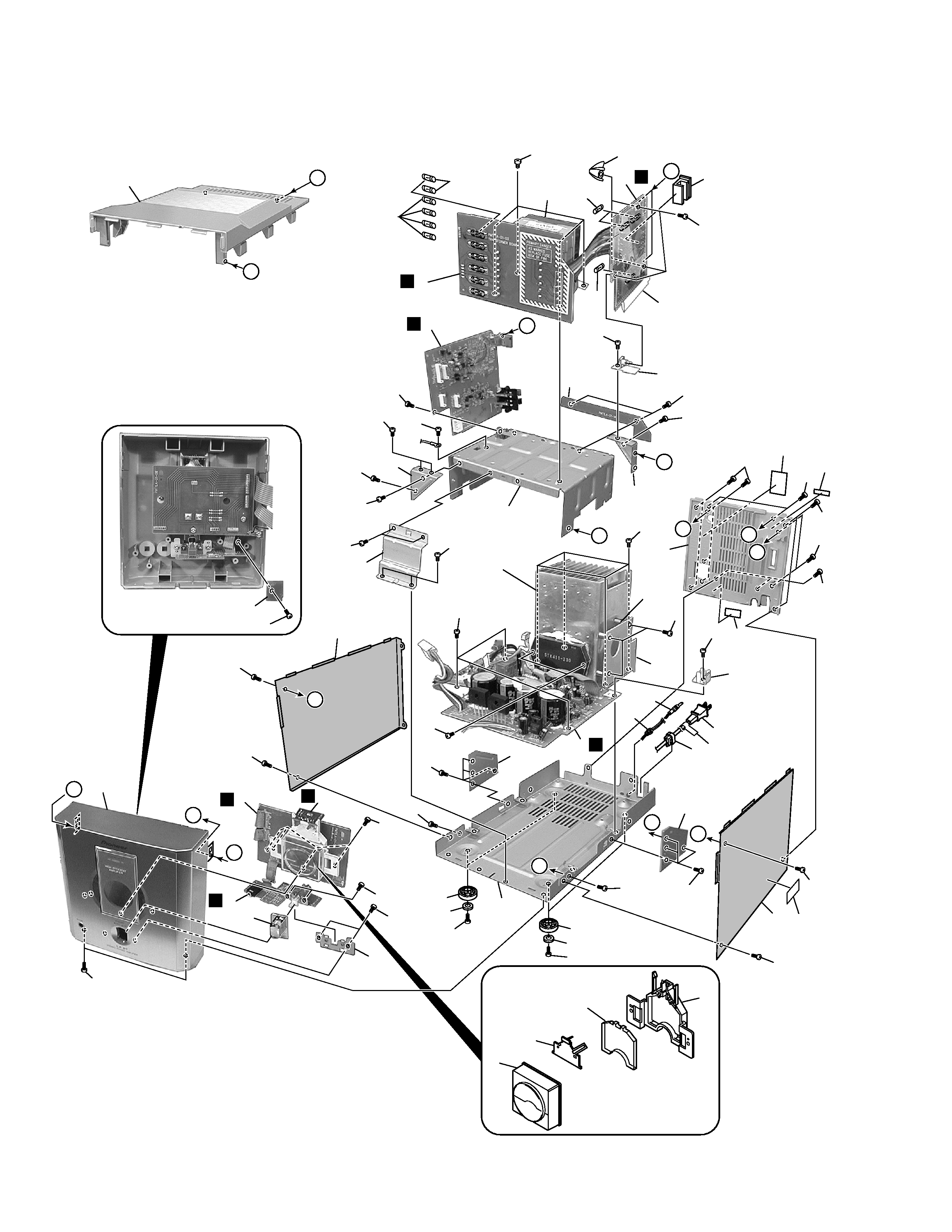
2.2 EXTERIOR SECTION
5
M-LA21
1
AMP Assy
PMT1LA100011
2
TRANSFORMER Assy
PMT1LA100031
3
PRIMARY Assy
PMT1LA100041
4
JACK Assy
PMT1LA100021
5
POWER METER Assy
PMT1LA100081
6
LED Assy
PMT1LA100051
7
HP JACK Assy
PMT1LA100111
8
· · · · ·
NSP
9
PROTECTION PCB
PMT1LA100141
10
S-Assy PMT3 FP01
SUBPMT3AMFP
11
Meter Assy
SUBPMT3MTR
NSP
12
Heat Sink Board
033PMT1LS100
13
DC Cord
122006020060
14
Transformer (TR701)
1236C0250140
15
Fuse
124010020001
(F322, F323 : T1AL/250V)
16
Fuse
124025020001
(F328, F329 : T2.5A/250V)
17
Fuse (F321 : T3.15A/250V)
124031520003
18
Fuse
124063020001
(F324-F327 : T6.3AL/250V)
19
AC Cord
See Contrast table (2)
20
Back Cover
See Contrast table (2)
21
Diffuser Lens
500PMT309000
22
Top Panel
500PMT311001
23
Meter Holder
505PMT307000
24
Lens Holder
505PMT308000
25
Rectifier PCB Bracket
505PMT370000
26
PCB Bracket-R
505PMT372000
27
Mounting Bracket
505266422000
28
Power Knob
510PMT312001
(1) EXTERIOR SECTION PARTS LIST
Mark No.
Description
Part No.
Mark No.
Description
Part No.
29
Voltage Selector Knob
510PMT319000
30
Side Panel-L
600PMT117002
31
Side Panel-R
600PMT118002
NSP
32
Bottom Tray
600PMT302000
33
Copper Post
603PMT381000
34
Power Switch Bracket
605PMT313000
35
Transformer Bracket
605PMT317000
36
Mounting Bracket-1
605PMT373000
37
Mounting Bracket-2
605PMT374000
38
Mounting Bracket-3
605PMT375000
39
Mounting Bracket-4
605PMT376000
40
· · · · ·
41
Heat Sink CDG-74
6130CDG74000
42
PCB Sheet
650PMT377000
43
Bushing
700PMT156000
44
Rubber Foot
700PMT384000
45
Strain Relief Bushing
700036022000
46
EMC Label
See Contrast table (2)
47
Back Label
See Contrast table (2)
NSP
48
Serial Label
809000009000
49
Screw
BBZ30P100FNI
50
Screw
BBZ30P180FMC
51
Screw
BBZ40P060FMC
52
Screw
BPZ30P100FNI
53
Screw
KBZ30P060FNI
54
Foot Stand
509PMT329000
55
Holding PCB
PMT1LA-100-121
56
Caution Label
See Contrast table (2)
57
AC Cord Label
See Contrast table (2)
(2) CONTRAST TABLE
M-LA21/DBDXCN and DDXCN/AR are constructed the same except for the following :
Part No.
Mark No.
Symbol and Description
M-LA21
M-LA21
Remarks
/DBDXCN
/DDXCN/AR
19
AC Cord
134250220000
134220120016
20
Back Cover
500PMT303000
500PMT388000
46
EMC Label
809PMT394030
Not used
47
Back Label
809PMT396040
809PMT396060
56
Caution Label
Not used
809PMT394070
57
AC Cord Label
Not used
809PMT394100