ORDER NO.
PIONEER ELECTRONIC CORPORATION 4-1, Meguro 1-Chome, Meguro-ku, Tokyo 153-8654, Japan
PIONEER ELECTRONICS SERVICE, INC. P.O. Box 1760, Long Beach, CA 90801-1760, U.S.A.
PIONEER ELECTRONIC (EUROPE) N.V. Haven 1087, Keetberglaan 1, 9120 Melsele, Belgium
PIONEER ELECTRONICS ASIACENTRE PTE. LTD. 253 Alexandra Road, #04-01, Singapore 159936
PIONEER ELECTRONIC CORPORATION 1999
ZUCXCN
--
DC power supplied from other system component
ZUCXCN1
--
DC power supplied from other system component
ZVYXCN
--
--
--
DC power supplied from other system component
MINI DISC RECORDER
RRV2134
TZZR MAY 1999 Printed in Japan
MJ-HX5000
CONTENTS
1. SAFETY INFORMATION .................................... 2
2. EXPLODED VIEWS AND PARTS LIST ............. 3
3. BLOCK DIAGRAM AND SCHEMATIC DIAGRAM 8
4. PCB CONNECTION DIAGRAM ....................... 19
5. PCB PARTS LIST ............................................. 26
6. ADJUSTMENT .................................................. 28
7. GENERAL INFORMATION .............................. 28
7.1 DIAGNOSIS ............................................... 28
7.2 PARTS ....................................................... 30
8. PANEL FACILITIES AND SPECIFICATIONS
................................................................... 32
THIS MANUAL IS APPLICABLE TO THE FOLLOWING MODEL(S) AND TYPE(S).
Type
MJ-HX5000MJ-HX3000 MJ-HX2000 MJ-HX700
Power Requirement
Remarks
Model
MJ-HX3000
MJ-HX2000
MJ-HX700
These products are component of systems.
This product does not operate normally by itself. Please connect it to the CD RECEIVER
SYSTEM, for adjustment and operation inspection. Otherwise damage may result.
¶ ZUCXCN type and ZUCXCN1 type are constructed the same.
MJ-HX5000, MJ-HX3000, MJ-HX2000, MJ-HX700
2
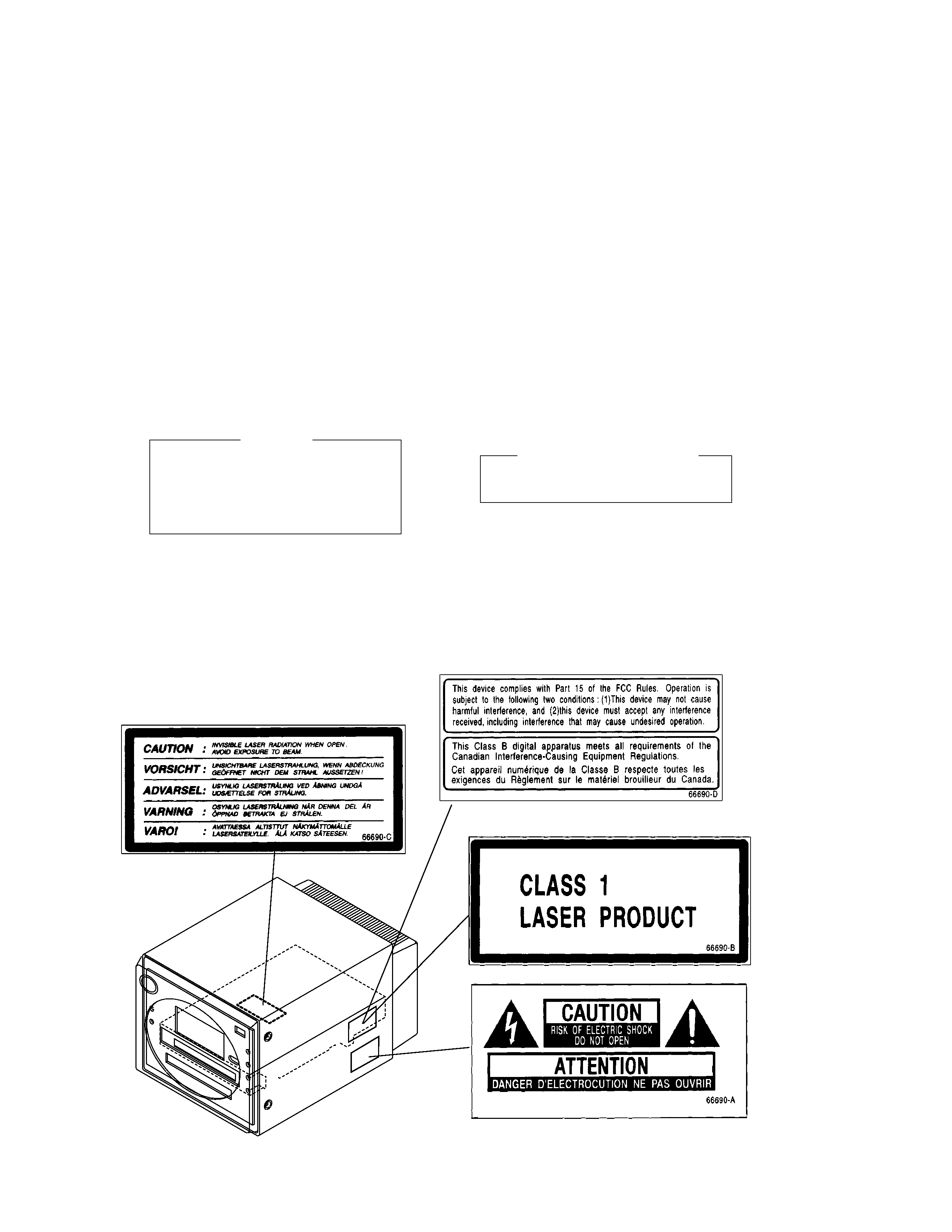
1. SAFETY INFORMATION
LABEL CHECK
IMPORTANT
THIS PIONEER APPARATUS CONTAINS
LASER OF CLASS 1.
SERVICING OPERATION OF THE APPARATUS
SHOULD BE DONE BY A SPECIALLY
INSTRUCTED PERSON.
LASER DIODE CHARACTERISTICS
MAXIMUM OUTPUT POWER: 5 mw
WAVELENGTH: 780 785 nm
This service manual is intended for qualified service technicians; it is not meant for the casual
do-it-yourselfer. Qualified technicians have the necessary test equipment and tools, and have been
trained to properly and safely repair complex products such as those covered by this manual.
Improperly performed repairs can adversely affect the safety and reliability of the product and may
void the warranty. If you are not qualified to perform the repair of this product properly and safely, you
should not risk trying to do so and refer the repair to a qualified service technician.
Excpet for MJ-HX700
MJ-HX700 type Only
MJ-HX700 type Only
WARNING
This product contains lead in solder and certain electrical parts contain chemicals which are known to the state of California to
cause cancer, birth defects or other reproductive harm.
Health & Safety Cod e Section 25249.6 Proposition 65
MJ-HX5000, MJ-HX3000, MJ-HX2000, MJ-HX700
3
3
Display Carton
66679-50U
66679-30U
66679-20U
66679-70
NSP
7
MD RECORDER
MJ-HX5000
MJ-HX3000
MJ-HX2000
MJ-HX700
/ZUCXCN
/ZUCXCN
/ZUCXCN
/ZVYXCN
9
Operating Instructions (German)
Not used
Not used
Not used
66780-MDG
10
Guarantee Card
66688-U
66688-U
66688-U
66688-Y/N
14
Safety Directions
66784-50U
66784-30U
66784-20U
66784-70V
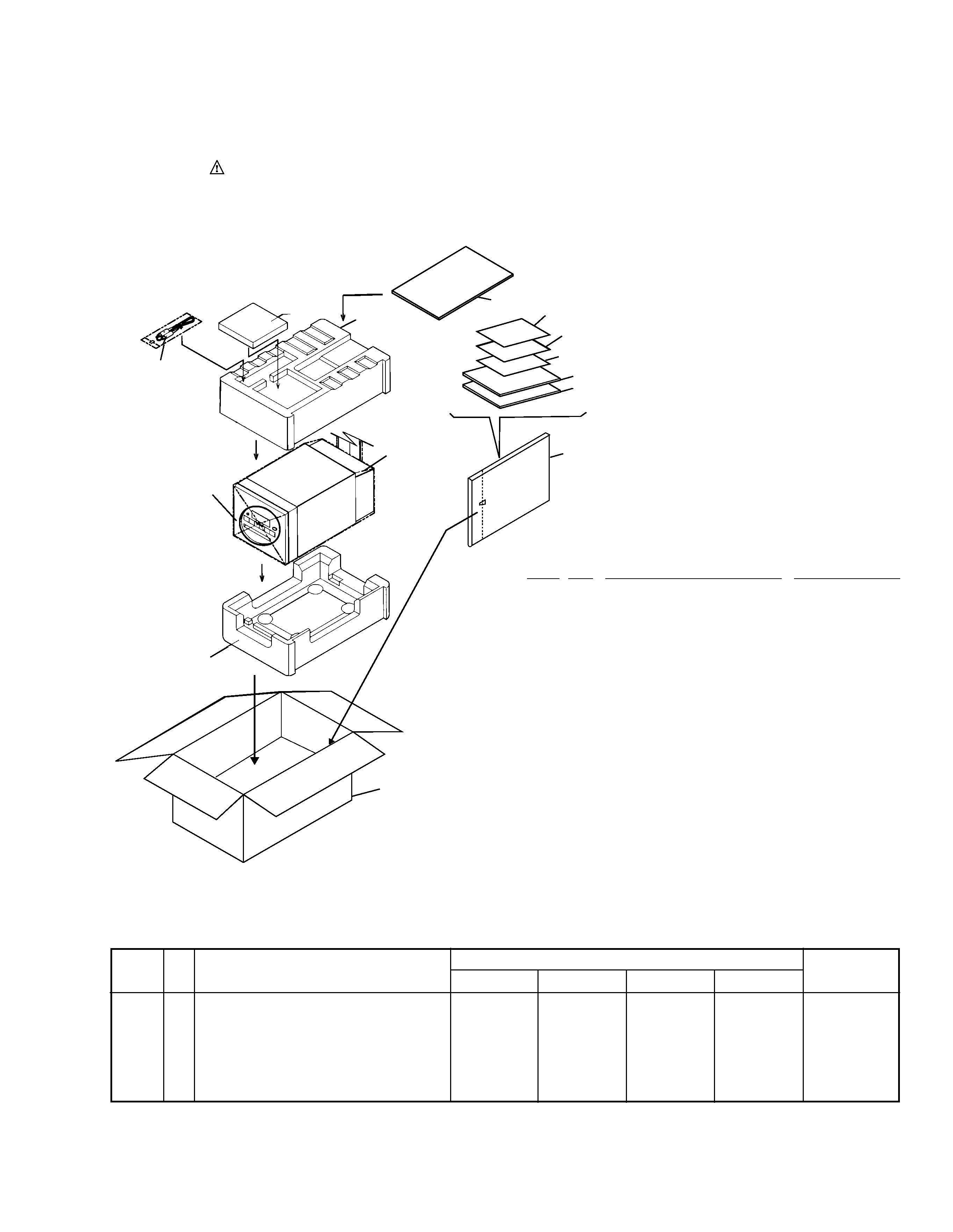
2. EXPLODED VIEWS AND PARTS LIST
2.1 PACKING
(1)PACKING PARTS LIST
1
Polyfoam (TOP)
66680
2
Polyfoam (BOTTOM)
66681
3
Display Carton
See Contrast table (2)
4
Mirormat Mat(380x300x0.5)
66694
5
Exclusive use CD-MD Cable
60233
(L=1.0 m)
6
Sound Scape MD
AFB7011-A
7
MD RECORDER
See Contrast table (2)
8
Operating Instructions (English) 66780-MDU
8
Operating Instructions (French)
66780-MDF
9
Operating Instructions
See Contrast table (2)
10
Guarantee Card
See Contrast table (2)
11
Polyethylene Bag
53117
(0.03
× 200 × 300)
12
Initial Instruction Manual
66783
13
Carton Sheet C
66669
14
Safety Directions
See Contrast table (2)
Mark No.
Description
Parts No.
(2) CONTRAST TABLE
MJ-HX5000, MJ-HX3000, MJ-HX2000 and MJ-HX700 are constructed the same except for the following:
NOTES :
÷ Parts marked by " NSP " are generally unavailable because they are not in our Master Spare Parts List.
÷ The
mark found on some component parts indicates the importance of the safety factor of the part.
Therefore, when replacing, be sure to use parts of identical designation.
÷ Screw adjacent to
mark on the product are used for disassembly.
6
1
5
2
7
3
4
9
8
13
11
10
14
12
MJ-HX5000 MJ-HX3000 MJ-HX2000
MJ-HX700
Part No.
Mark
Remarks
Symbol and Description
No.

MJ-HX5000, MJ-HX3000, MJ-HX2000, MJ-HX700
4
2.2 EXTERIOR
39
41
8
40
42
45
32
9
32
32
46
8
43
38
44
37
17
16
15
14
13
12
36
35
51
52
8
8
32
32
8
8
8
8
8
8
7
5
6
3
2
1
4
11
10
9
9
9
18
19
22
21
Refer to "2.3 MD MECHA. (1/2)"
"2.4 MD MECHA. (2/2)"
23
24
48
25
26
27
28
31
33
44
34
34
34
50
40
49
34
34
8
29
20
23
47
53
30
34
A
B
A
B
MJ-HX5000, MJ-HX3000, MJ-HX2000, MJ-HX700
5
NSP
1
Front Cover (A, B)
66714-05M
66715-03M
66714-02M
66714-K7M
NSP
2
Front Door (A, B)
66708-05M
66709-03M
66708-02M
66708-K7M
3
Button B (MD)
66717-05M
66717-03M
66717-02M
66717-K7M
10
MD Front Case
66702-05
66702-03
66702-02
66702-K7
11
Button D (REC)
66719-05R
66719-03R
66719-02R
66719-K7R
19
Eject Button
66721-05
66721-03
66721-02
66721-K7
20
Button C (MD EDIT)
66718-05ME
66718-03ME
66718-02ME
66718-K7ME
24
Inner Panel (MD)
66711-05M
66711-03M
66711-02M
66711-K7M
36
Leg Rubber (A, B)
66758-01
66758-02
66758-02
66758-01
37
Foot (A, B)
66722-05
66723-03
66723-02
66722-K7
38
MD Rear Case
66704-05
66704-03
66704-02
66704-K7
46
Back Plate (MD)
66762-50U
66762-30U
66762-20U
66762-70
47
Front Door Assy (MD)
10000-05M
10000-03M
10000-02M
10000-K7M
52
Label Plate
66690B
66690B
66690B
66690E
53
Label Plate (MD Caution A)
Not used
Not used
Not used
66690A
(1) EXTERIOR PARTS LIST
Mark No.
Description
Parts No.
(2) CONTRAST TABLE
MJ-HX5000, MJ-HX3000, MJ-HX2000 and MJ-HX700 are constructed the same except for the following:
NSP
1
Front Cover A, B (MD)
See Contrast table (2)
NSP
2
Front Door A, B (MD)
See Contrast table (2)
3
Button B (MD)
See Contrast table (2)
4
Lens
66734-MD
5
Cushion A
66795
6
Door Shaft A
66746
7
Dumper Gear
60227
8
Screw PAN TAPP. T3x10
PMZ30P100FNI
9
Plate Nut
66741
10
MD Front Case
See Contrast table (2)
11
Button D (REC)
See Contrast table (2)
12
LCD Window
66735
13
LCD Assy
52715
14
LCD Sheet
66756
15
LCD Holder
66727
16
MD COMBI PCB Assy
66785C
(LED PCB)
17
MD COMBI PCB Assy
66785A
(FRONT PCB)
18
Push Door Lock
60226
19
Eject Button
See Contrast table (2)
20
Button C (MD EDIT)
See Contrast table (2)
21
MD Mechanism Assy
61416
22
Front Door Spring
66748
23
Screw PAN TAPP. T2x8
PBZ20P080FMC
24
Inner Panel (MD)
See Contrast table (2)
25
MD Door
66732
26
MD Door Shaft
66750
27
MD Door Spring
66751
28
Screw PAN M3x6
PMZ30P060FZK
29
Screw BIND TAPP. M3x6
BMZ30P060FZK
30
Shield Case (Bottom)
66739
31
Shield Case (Up)
66738
32
Screw PLAT M3x6
CMZ30P060FNI
33
MD COMBI PCB Assy
66785B
(AD/DA PCB)
34
Screw PAN M2x4
PMZ20P040FZK
35
Screw PAN M3x10
PBZ30P100FMC
36
Leg Rubber (A, B)
See Contrast table (2)
37
Foot (A, B)
See Contrast table (2)
38
MD Rear Case
See Contrast table (2)
39
12P Connector Holder A
66728
NSP
40
12P Connector Assy
66763
41
12P Connector Holder B
66729
42
Wire Clamper
66726
43
10P Connector Holder A
66730
NSP
44
10P Connector Assy
66778
45
10P Connector Holder B
66731
46
Back Plate (MD)
See Contrast table (2)
47
Front Door Assy A,B (MD)
See Contrast table (2)
48
Panel Tape B
66761
49
16P FFC (SUMI Card)
66775
50
19P FFC (SUMI Card)
66776
51
Label Plate (CAUTION)
66690I
52
Label Plate
See Contrast table (2)
53
Label Plate (MD Caution A)
See Contrast table (2)
Mark No.
Description
Parts No.
MJ-HX5000 MJ-HX3000 MJ-HX2000
MJ-HX700
Part No.
Mark
Remarks
Symbol and Description
No.