ORDER NO.
PIONEER ELECTRONIC CORPORATION
4-1, Meguro 1-Chome, Meguro-ku, Tokyo 153-8654, Japan
PIONEER ELECTRONICS SERVICE, INC. P.O. Box 1760, Long Beach, CA 90801-1760, U.S.A.
PIONEER ELECTRONIC (EUROPE) N.V . Haven 1087, Keetberglaan 1, 9120 Melsele, Belgium
PIONEER ELECTRONICS ASIACENTRE PTE. LTD. 253 Alexandra Road, #04-01, Singapore 159936
PIONEER ELECTRONIC CORPORATION 1999
7. GENERAL INFORMATION .............................. 49
7.1 DIAGNOSIS ................................................ 49
7.1.1 TROUBLESHOOTING ...................... 49
7.1.2 DISASSEMBLY ................................. 52
7.2 PARTS ....................................................... 55
7.2.1 IC ....................................................... 45
7.2.2 DISPLAY ........................................... 66
8. PANEL FACILITIES AND SPECIFICATIONS
....................................................... 68
MINIDISC RECORDER
RRV2144
MJ-D508
1. SAFETY INFORMATION .................................... 2
2. EXPLODED VIEWS AND PARTS LIST ............. 4
3. BLOCK DIAGRAM AND SCHEMATIC DIAGRAM
....................................................... 12
4. PCB CONNECTION DIAGRAM ....................... 28
5. PCB PARTS LIST ............................................. 37
6. ADJUSTMENT .................................................. 41
CONTENTS
TZZE MAY 1999 Printed in Japan
Type
Power Requirement
Remarks
Model
MJ-D508
THIS MANUAL IS APPLICABLE TO THE FOLLOWING MODEL(S) AND TYPE(S).
KUXJ
AC120V
MYXJ
AC220230V
MYXJGR/FR
AC220230V
NVXJ
AC230V
DAC
MODE
INPUT
SELECTOR
DISPLAY
/CHARA
NAME
CLIP
REC/PLAY
MODE
SYNCHRO
REC
DIGITAL
REC LEVEL
4
¢
ANALOG
REC LEVEL
EDIT/NO
!/
&
*
#
NAME
PUSH ENTER
LEVEL
PHONES
MIN
MAX
AB
0 EJECT
DISC LOADING MECHANISM
POWER
MINIDISC RECORDER
OFF - ON
DIGITAL
NR
TIMER
REC OFF PLAY
vC¿Û.?
1
0
2
3
4
5
6
7
8
9
10
MJ-D508
2
1. SAFETY INFORMATION
This service manual is intended for qualified service technicians; it is not meant for the casual
do-it-yourselfer. Qualified technicians have the necessary test equipment and tools, and have been
trained to properly and safely repair complex products such as those covered by this manual.
Improperly performed repairs can adversely affect the safety and reliability of the product and may
void the warranty. If you are not qualified to perform the repair of this product properly and safely, you
should not risk trying to do so and refer the repair to a qualified service technician.
WARNING
This product contains lead in solder and certain electrical parts contain chemicals which are known to the state of California to
cause cancer, birth defects or other reproductive harm.
Health & Safety Code Section 25249.6 Proposition 65
NOTICE
(FOR CANADIAN MODEL ONLY)
Fuse symbols
(fast operating fuse)
and/or
(slow operating fuse) on PCB indicate that replacement
parts must be of identical designation.
REMARQUE
(POUR MODÈLE CANADIEN SEULEMENT)
Les symboles de fusible
(fusible de type rapide)
et/ou
(fusible de type lent) sur CCI indiquent que
les pièces de remplacement doivent avoir la même désignation.
ANY MEASUREMENTS NOT WITHIN THE
LIMITS OUTLINED ABOVE ARE INDICATIVE
OF A POTENTIAL SHOCK HAZARD AND
MUST BE CORRECTED BEFORE RETURN-
ING THE APPLIANCE TO THE CUSTOMER.
2. PRODUCT SAFETY NOTICE
Many electrical and mechanical parts in the appliance
have special safety related characteristics. These are
often not evident
from visual
inspection nor the
protection afforded by them necessarily can be obtained
by using replacement components rated for voltage,
wattage, etc. Replacement parts which have these
special safety characteristics are identified in this
Service Manual.
Electrical components having such features are
identified by marking with a
on the schematics and
on the parts list in this Service Manual.
The use of a substitute replacement component which
does not have the same safety characteristics as the
PIONEER recommended replacement one, shown in the
parts list in this Service Manual, may create shock, fire,
or other hazards.
Product Safety is continuously under review and new
instructions are issued from time to time. For the latest
information, always consult the current PIONEER
Service Manual. A subscription to, or
additional copies
of, PIONEER Service Manual may be obtained at a
nominal charge from PIONEER.
(FOR USA MODEL ONLY)
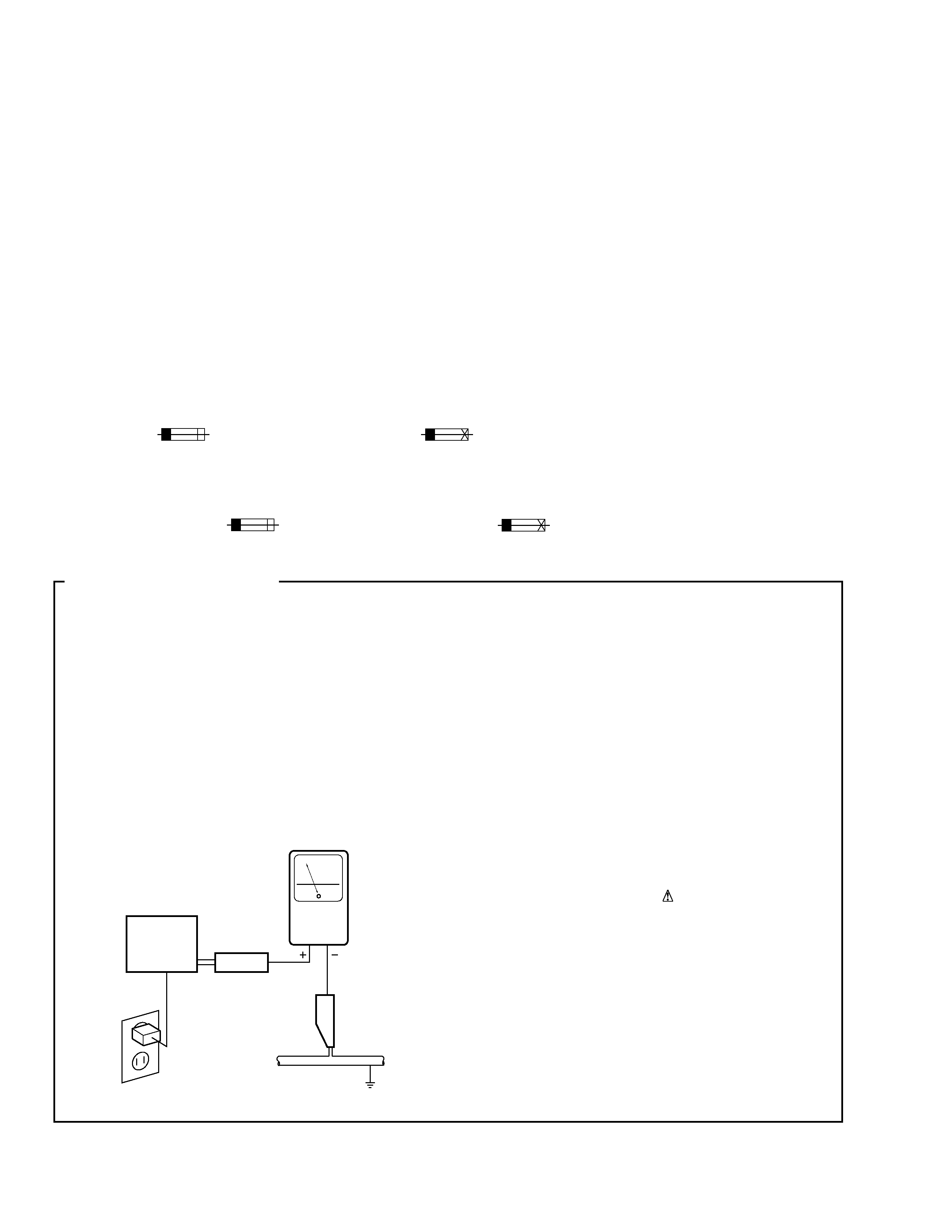
1. SAFETY PRECAUTIONS
The following check should be performed for the
continued protection of the customer and service
technician.
LEAKAGE CURRENT CHECK
Measure leakage current to a known earth ground
(water pipe, conduit, etc.) by connecting a leakage
current tester such as Simpson Model 229-2 or
equivalent between the earth ground and all exposed
metal parts of the appliance (input/output terminals,
screwheads, metal overlays, control shaft, etc.). Plug
the AC line cord of the appliance directly into a 120V
AC 60 Hz outlet and turn the AC power switch on. Any
current measured must not exceed 0.5 mA.
Device
under
test
Leakage
current
tester
Earth
ground
Reading should
not be above
0.5 mA
Also test with
plug reversed
(Using AC adapter
plug as required)
Test all
exposed metal
surfaces
AC Leakage Test
MJ-D508
3
IMPORTANT
THIS PIONEER APPARATUS CONTAINS
LASER OF CLASS 1.
SERVICING OPERATION OF THE APPARATUS
SHOULD BE DONE BY A SPECIALLY
INSTRUCTED PERSON.
LASER DIODE CHARACTERISTICS
MAXIMUM OUTPUT POWER: 27.4 mW
WAVELENGTH: 785 nm
Control method of the current through a laser diode.
The resistor R105 on the CORD MAIN UNIT ASSY (For MD
mechanism assembly) are for the limiting of current through a laser
diode.
Control method of the laser output power
The laser pick-up assembly provide the photo-diodes and APC
(Auto Power Control) circuit.
The photo-diode detect output of the laser diode then IC104 control
the APC circuit according to the signal voltage of the photo-diode via
IC101.
The Variable resistancer on the FPC in the Laser pick-up assembly
can be adjusted the output level of Laser diode to fix the rated output
level.
Laser Interlock Switch
The loading position detect switch S101 is set to " LOAD ON " (ON:
low level, OFF: high level) position, IC104 get the " LOAD " signal,
and hand the laser " LDON " signal to No. 9 terminal (LDON) of the
Laser pick-up assembly.
Then a laser diode can be lighted exept when the level of signal
"LOAD " is low.
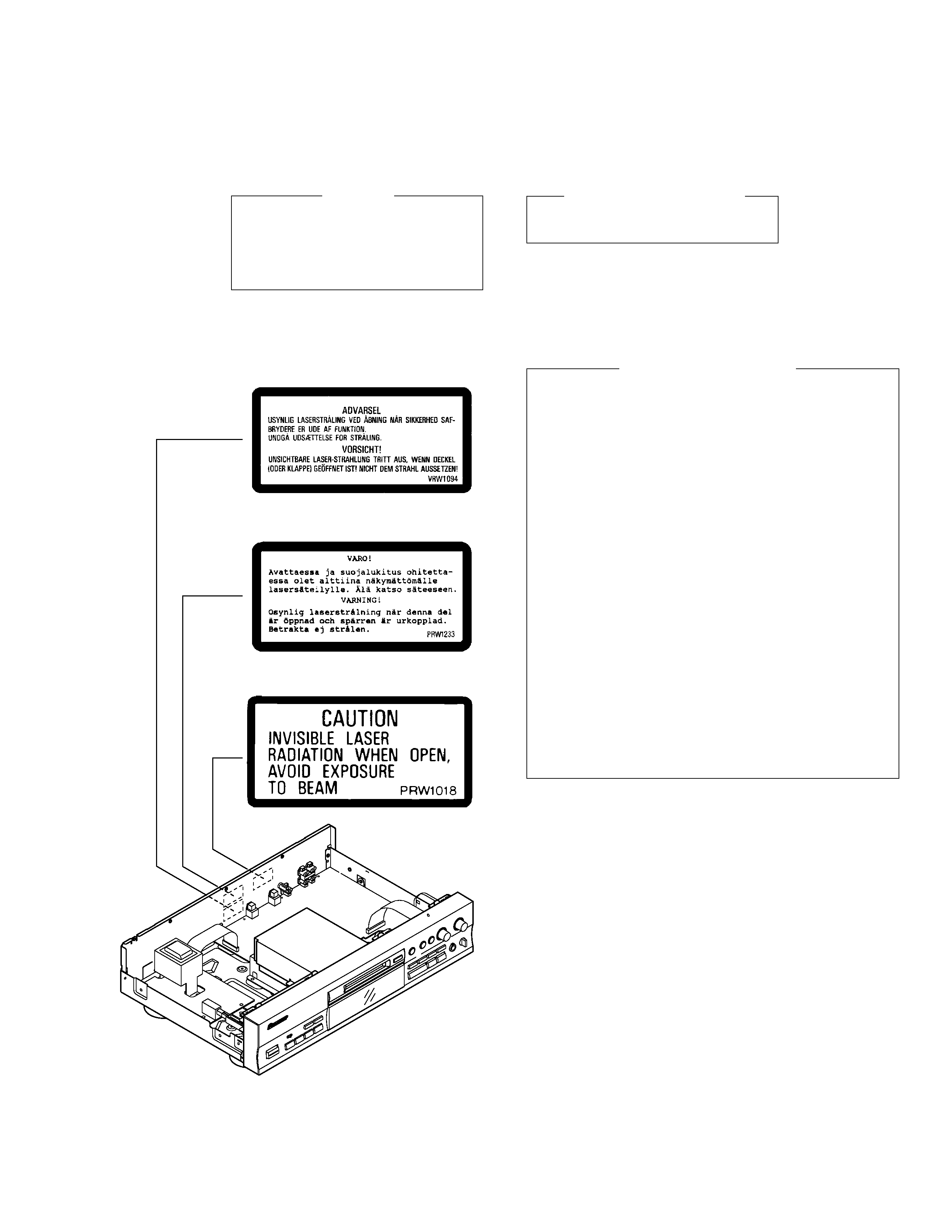
Additional Laser Caution
LABEL CHECK
NVXJ type
MYXJ and MYXJGR/FR types
MYXJ and MYXJGR/FR types
Refer to page 42.
MJ-D508
4
RAN
DOM
HI-LIT
E
MED
LEY FAD
ER
REPE
ATP
GM
CHEC
K
CLEA
R
DISP
/
CHAR
A
EDIT
/NO
ENTE
R
A
B
SYN
CHRO
REC
REC
CURS
OR
1
2
3
4
5
6
&
*
#
!
!
$
$
3
8
11 (KUXJ, MYXJ and NVXJ types only)
10
7
6
9
5
4
1 (1/2)
2 (1/2)
2 (2/2)
1 (2/2)
12 (MYXJ and MYXJGR/FR types only)
MYXJ type only
13
14
15
16 (MYXJ, MYXJGR/FR
and NVXJ types only)
18
3
Front
17
1 (1/2)
2 (1/2)
1 (2/2)
2 (2/2)
NVXJ type only
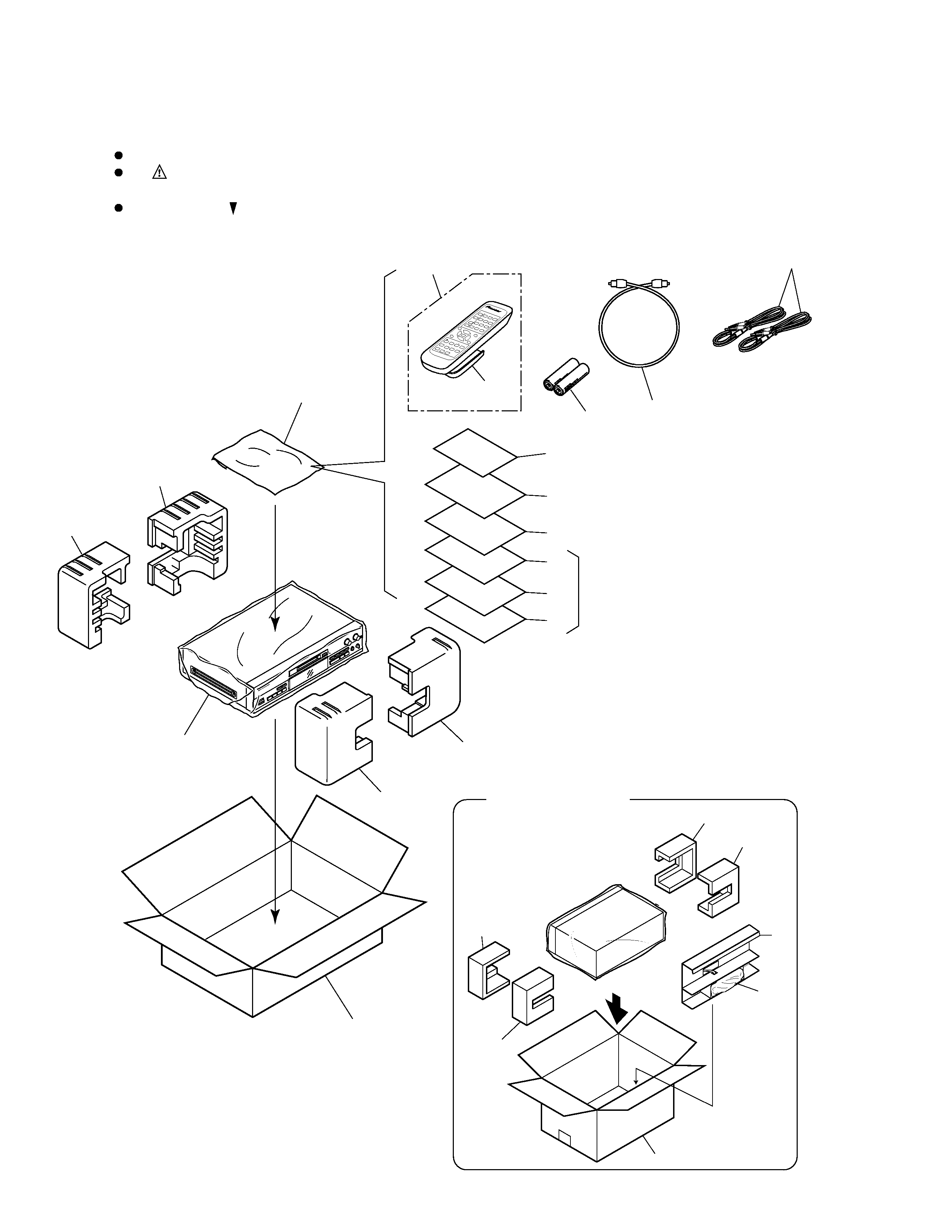
2. EXPLODED VIEWS AND PARTS LIST
NOTES :
Parts marked by " NSP " are generally unavailable because they are not in our Master Spare Parts List.
The
mark found on some component parts indicates the importance of the safety factor of the part.
Therefore, when replacing, be sure to use parts of identical designation.
Screw adjacent to
mark on the product are used for disassembly.
2.1 PACKING
MJ-D508
5
Mark No.
Description
Part No.
(1) PACKING PARTS LIST
(2) CONTRAST TABLE
1
Protector (F)
PHA1339
2
Protector (R)
PHA1340
3
Packing Case
See Contrast table (2)
4
Sheet (750
× 600 × 0.5)
Z23007
5
Stereo Audio Cord (L= 1m)
RDE1036
6
Remote Control Unit
PWW1157
(CU-MJ016)
7
Battery Cover
RZN1156
NSP
8
Batteries (AA/R6P)
VEM013
9
Polyethylene Bag
Z21038
(0.03
× 230 × 340)
NSP
10
Warranty Card
See Contrast table (2)
MJ-D508/KUXJ, MYXJ, MYXJGR/FR and NVXJ are constructed the same except for the following:
3
Packing Case
PHG2386
PHG2387
PHG2387
PHG2364
NSP
10
Warranty Card
ARY7023
ARY7022
ARY7022
ARY7022
11
Operating Instructions (English)
PRB1285
PRB1285
not used
PRB1285
12
Operating Instructions (French/German)
not used
PRD1044
PRD1044
not used
13
Operating Instructions (Italian/Dutch)
not used
PRD1045
not used
not used
14
Operating Instructions (Spanish)
not used
PRD1046
not used
not used
15
Operating Instructions
not used
PRD1058
not used
not used
(Portuguese/Swedish)
16
Optical Digital Cord (L= 0.8m)
not used
ADE7021
ADE7021
ADE7021
17
V Spacer
not used
not used
not used
PHC1092
18
Vinyl Bag
not used
not used
not used
Z21-013
KUXJ
MYXJ
MYXJGR/FR
NVXJ
Part No.
Mark
Remarks
Symbol and Description
No.
MJ-D508
Mark No.
Description
Part No.
11
Operating Instructions
See Contrast table (2)
12
Operating Instructions
See Contrast table (2)
13
Operating Instructions
See Contrast table (2)
14
Operating Instructions
See Contrast table (2)
15
Operating Instructions
See Contrast table (2)
16
Optical Digital Cord
See Contrast table (2)
17
V Spacer
See Contrast table (2)
18
Vinyl Bag
See Contrast table (2)
NAME
G H I
J K L
DISP/CHARA
SYNCHRO REC
M N O
EDIT/NO
HI-LITE
REPEAT
CHECK
CLEAR
RANDOM
PROGRAM
MEDLEY
A B C
D E F
NAME CLIP
P Q R S
T U V
MARK
W X Y Z
FADER
REC
TIME SKIP
A
B
CURSOR
1
2
3
4
5
6
7
8
9
10
10/0
>10
!
!
Î
MINIDISC RECORDER
REMOTE CONTROL UNIT
&
#
$
$
ENTER
*
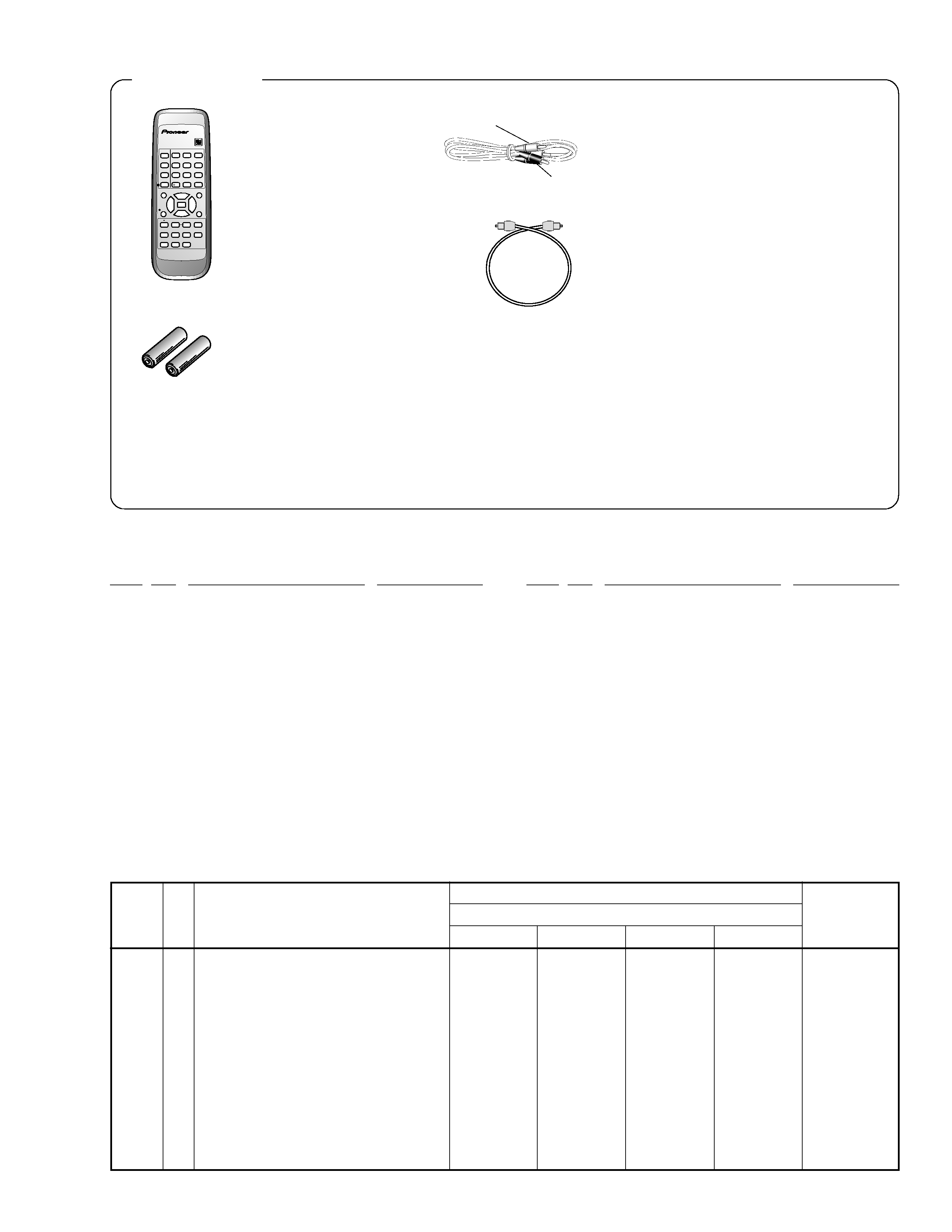
Remote control unit
CU-MJ016 (PWW1157)
Batteries (AA/R6P) x 2
(VEM013)
Accessories
Stereo Audio cord x 2
(RDE1036) (L = 1m)
White
Red
Optical digital cord x 1
(MYXJ, MYXJGR/FR and NVXJ types only)
(ADE7021) (L = 0.8m)
Other included items
÷ Warranty card (ARY7023: KUXJ type)
(ARY7022: MYXJ, MYXJGR/FR and NVXJ types)
÷ Operating Instructions
(PRB1285: KUXJ, MYXJ, MYXJGR/FR and NVXJ types)
(PRD1044: MYXJ and MYXJGR/FR types)
(PRD1045: MYXJ type)
(PRD1046: MYXJ type)
(PRD1058: MYXJ type)