ENG/MASTER 97
ENGLISH
Multi-CD/MD control High power Minidisc player
with RDS tuner
MEH-P5000R
Operation Manual
ESPAÑOL
DEUTSCH
FRANÇAIS
ITALIANO
NEDERLANDS
1

2
Contents
ENG/MASTER 98
2
Connecting the Units ................................ 5
RFP Alert Installation ................................ 8
Description ........................................................ 8
Door Switches .................................................. 8
DOOR SWITCH (White/Yellow) .................... 9
-
Grounding Type Switch:
-
Positive (Non-grounding) Type Switch:
-
Installing New Pin Switches
Installation ................................................ 11
Installation with the rubber bush .................... 12
Removing the Unit .......................................... 13
Key Finder .................................................. 14
-
Head Unit
-
Remote Controller (CD-R66)
Before Using This Product .................... 15
About This Product ........................................ 15
About This Manual .......................................... 15
About Optional Remote Controller (CD-R66) .. 16
Resetting the Microprocessor .......................... 16
Precaution ........................................................ 17
In Case of Trouble .......................................... 17
Basic Operation ...................................... 18
To Listen to Music .......................................... 18
Basic Operation of Tuner ................................ 20
-
Manual and Seek Tuning
-
Band
-
Preset Tuning
Basic Operation of Built-in MD Player .......... 21
-
Switching the Display
-
Scrolling the Display
-
Disc Loading Slot
-
Eject
-
Track Search and Fast Forward/Reverse
Basic Operation of Multi-CD Player .............. 22
-
Switching the Multi-CD Player
-
Switching the Display
-
Disc Search
-
Track Search and Fast Forward/Reverse
-
Disc Number Search
(for 6-Disc, 12-Disc types)
-
Disc Number Rough Search
(for 50-Disc type only)
Corresponding Display Indications and
Buttons ...................................................... 24
Entering the Function Menu ............................ 24
Function Menu Functions ................................ 25
Entering the Detailed Setting Menu ................ 27
Detailed Setting Menu Functions .................... 28
Tuner Operation ...................................... 29
-
Local Seek Tuning (LOCAL)
-
Best Stations Memory (BSM)
Using RDS Functions .............................. 30
What is RDS ? ................................................ 30
Program Service Name Display ...................... 30
AF Function (AF) ............................................ 31
-
Activating/Deactivating the AF Function
PI Seek Function ............................................ 32
-
PI Seek
-
Auto PI Seek (for preset station)
Regional Function (REG) ................................ 32
-
Activating REG
TA Function (TA) .......................................... 33
-
Activating/Deactivating the TA Function
-
Canceling Traffic Announcements
-
Adjusting the TA Volume
-
TP Alarm Function
PTY Function .................................................. 35
-
Searching the PTY
-
News Program Interruption Setting
-
PTY Alarm
-
Canceling Emergency Announcements
-
PTY List
Using the Built-in MD Player ................ 39
-
Repeat Play (REPEAT)
-
Random Play (RANDOM)
-
Scan Play (T-SCAN)
-
Pause (PAUSE)
Using Multi-CD Players .......................... 41
-
Repeat Modes (REPEAT)
-
Random Play (RANDOM)
-
Scan Play (SCAN)
-
Pause (PAUSE)
-
CD Sound Quality Adjustment (COMP)
ITS (Instant Track Selection) .......................... 44
-
ITS Programming (ITS)
-
ITS Play (ITS-P)
-
Erase a Track Pprogram
-
Erase a Disc Program
Disc Title ........................................................ 46
-
Disc Title Input (TITLE IN)
-
Disc Title List (TITLE LIST)

3
ENGLISH
ESPAÑOL
DEUTSCH
FRANÇAIS
ITALIANO
NEDERLANDS
ENG/MASTER 98
3
Audio Adjustment .................................... 48
Selecting the Equalizer Curve ........................ 48
Entering the Audio Menu ................................ 48
Audio Menu Functions .................................... 49
-
Balance Adjustment (FADER)
-
Equalizer Curve Adjustment
(EQ-LOW/MID/HIGH)
-
Equalizer Curve Fine Adjustment
-
Loudness Adjustment (LOUD)
-
Front Image Enhancer Function (FIE)
-
Source Level Adjustment (SLA)
Detaching and Replacing
the Front Panel .................................. 52
Theft Protection .............................................. 52
-
Detaching the Front Panel
-
Replacing the Front Panel
-
Warning Tone
Initial Setting ............................................ 53
Entering the Initial Setting Menu .................... 53
Initial Setting Menu Functions ........................ 54
-
Setting the Time
-
Changing the FM Tuning Step (FM STEP)
-
Switching the Auto PI Seek (A-PI)
-
Setting the Warning Tone (WARN)
-
Swithing the AUX Mode (AUX)
-
Setting the Dimmer (DIMMER)
-
Selecting the Illumination Color (ILL. CLR)
RFP Alert Function .................................. 57
Activating the RFP Alert Feature .................... 57
Setting Entry Delay Time ................................ 57
Activating Internal Speaker ON/OFF ............ 58
-
Speaker Volume Output Adjustment
Selecting Door Switching Systems ................ 59
-
Door System Confirmation
Operation of "RFP Alert" ................................ 60
Arming Alert .................................................. 60
Disarming Alert .............................................. 60
Entry Detection .............................................. 60
Other Functions ........................................ 61
Time Display .................................................. 61
-
Displaying the Time
Using the PGM Button (PGM-FUNC) ............ 61
-
Setting the PGM Button
-
Using the PGM Button
Using the AUX Source .................................... 63
-
Selecting the AUX Source
-
AUX Title Input
Cellular Telephone Muting ............................ 63
MD Player and Care ................................ 64
Precaution ........................................................ 64
Built-in MD Player's Error Message .............. 65
Specifications .......................................... 66

4
ENG/MASTER 98
4
Connecting the Units
5
ENGLISH
ESPAÑOL
DEUTSCH
FRANÇAIS
ITALIANO
NEDERLANDS
ENG/MASTER 98
5
Note:
· This unit is for vehicles with a 12-volt battery and
negative grounding. Before installing it in a recre-
ational vehicle, truck, or bus, check the battery
voltage.
· To avoid shorts in the electrical system, be sure to
disconnect the battery cable before beginning
installation.
· Refer to the owner's manual for details on con-
necting the power amp and other units, then make
connections correctly.
· Secure the wiring with cable clamps or adhesive
tape. To protect the wiring, wrap adhesive tape
around them where they lie against metal parts.
· Route and secure all wiring so it cannot touch any
moving parts, such as the gear shift, handbrake,
and seat rails. Do not route wiring in places that
get hot, such as near the heater outlet. If the insu-
lation of the wiring melts or gets torn, there is a
danger of the wiring short-circuiting to the vehicle
body.
· Don't pass the yellow lead through a hole into the
engine compartment to connect to the battery.
This will damage the lead insulation and cause a
very dangerous short.
· Do not shorten any leads. If you do, the protection
circuit may fail to work when it should.
· Never feed power to other equipment by cutting
the insulation of the power supply lead of the unit
and tapping into the lead. The current capacity of
the lead will be exceeded, causing overheating.
· When replacing fuse, be sure to use only fuse of
the rating prescribed on the fuse holder.
· Since a unique BPTL circuit is employed, never
wire so the speaker leads are directly grounded or
the left and right speaker leads are common.
· The black lead is ground. Please ground this lead
separately from the ground of high-current prod-
ucts such as power amps.
If you ground the products together and the
ground becomes detached, there is a risk of dam-
age to the products or fire.
· Speakers connected to this unit must be high-
power types possessing minimum rating of 40 W
and impedance of 4 to 8 ohms. Connecting speak-
ers with output and/or impedance values other
than those noted here can damage the speakers.
· When an external power amp is being used with
this system, be sure not to connect the blue/white
lead to the amp's power terminal. Likewise, do
not connect the blue/white lead to the power ter-
minal of the auto-antenna. Such connection could
cause excessive current drain and malfunction.
· To prevent incorrect connection, the input side of
the IP-BUS connector is blue, and the output side
is black. Connect the connectors of the same col-
ors correctly.
· If this unit is installed in a vehicle that does not
have an ACC (accessory) position on the ignition
switch, the red lead of the unit should be connect-
ed to a terminal coupled with ignition switch
ON/OFF operations. If this is not done, the vehi-
cle battery may be drained when you are away
from the vehicle for several hours.
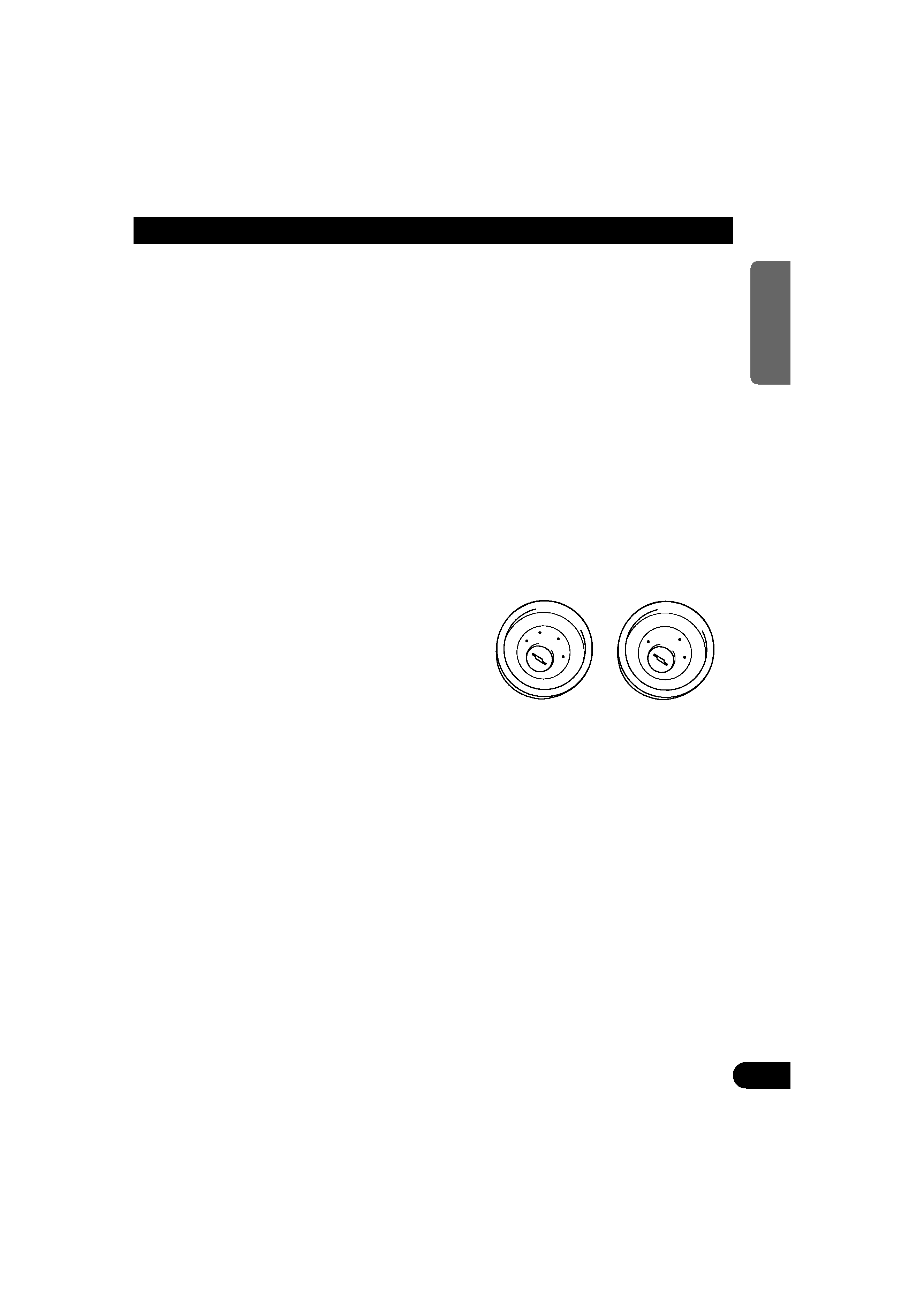
No ACC position
ACC position
ON
S
T
A
R
T
O
FF
ACC
ON
S
T
A
R
T
O
FF
Note:
· This unit is for vehicles with a 12-volt battery and
negative grounding. Before installing it in a recre-
ational vehicle, truck, or bus, check the battery
voltage.
· To avoid shorts in the electrical system, be sure to
disconnect the battery cable before beginning
installation.
· Refer to the owner's manual for details on con-
necting the power amp and other units, then make
connections correctly.
· Secure the wiring with cable clamps or adhesive
tape. To protect the wiring, wrap adhesive tape
around them where they lie against metal parts.
· Route and secure all wiring so it cannot touch any
moving parts, such as the gear shift, handbrake,
and seat rails. Do not route wiring in places that
get hot, such as near the heater outlet. If the insu-
lation of the wiring melts or gets torn, there is a
danger of the wiring short-circuiting to the vehicle
body.
· Don't pass the yellow lead through a hole into the
engine compartment to connect to the battery.
This will damage the lead insulation and cause a
very dangerous short.
· Do not shorten any leads. If you do, the protection
circuit may fail to work when it should.
· Never feed power to other equipment by cutting
the insulation of the power supply lead of the unit
and tapping into the lead. The current capacity of
the lead will be exceeded, causing overheating.
· When replacing fuse, be sure to use only fuse of
the rating prescribed on the fuse holder.
· Since a unique BPTL circuit is employed, never
wire so the speaker leads are directly grounded or
the left and right speaker leads are common.
· The black lead is ground. Please ground this lead
separately from the ground of high-current prod-
ucts such as power amps.
If you ground the products together and the
ground becomes detached, there is a risk of dam-
age to the products or fire.
· Speakers connected to this unit must be high-
power types possessing minimum rating of 40 W
and impedance of 4 to 8 ohms. Connecting speak-
ers with output and/or impedance values other
than those noted here can damage the speakers.
· When an external power amp is being used with
this system, be sure not to connect the blue/white
lead to the amp's power terminal. Likewise, do
not connect the blue/white lead to the power ter-
minal of the auto-antenna. Such connection could
cause excessive current drain and malfunction.
· To prevent incorrect connection, the input side of
the IP-BUS connector is blue, and the output side
is black. Connect the connectors of the same col-
ors correctly.
· If this unit is installed in a vehicle that does not
have an ACC (accessory) position on the ignition
switch, the red lead of the unit should be connect-
ed to a terminal coupled with ignition switch
ON/OFF operations. If this is not done, the vehi-
cle battery may be drained when you are away
from the vehicle for several hours.
No ACC position
ACC position
ON
S
T
A
R
T
O
FF
ACC
ON
S
T
A
R
T
O
FF