ORDER NO.
PIONEER CORPORATION 4-1, Meguro 1-chome, Meguro-ku, Tokyo 153-8654, Japan
PIONEER ELECTRONICS SERVICE, INC. P.O. Box 1760, Long Beach, CA 90801-1760, U.S.A.
PIONEER EUROPE NV Haven 1087, Keetberglaan 1, 9120 Melsele, Belgium
PIONEER ELECTRONICS ASIACENTRE PTE. LTD. 253 Alexandra Road, #04-01, Singapore 159936
PIONEER CORPORATION 2000
c
M-AX10
RRV2345
1. SAFETY INFORMATION ...................................... 2
2. EXPLODED VIEWS AND PARTS LIST ................ 3
3. SCHEMATIC DIAGRAM ..................................... 12
4. PCB CONNECTION DIAGRAM .......................... 24
5. PCB PARTS LIST ............................................... 36
6. ADJUSTMENT .................................................... 41
CONTENTS
7. GENERAL INFORMATION ................................ 42
7.1 IC ................................................................. 42
7.2 PROTECTION CIRCUIT ............................. 52
7.3 EXPLANATION ............................................ 54
7.3.1 PRODUCT OVERVIEW ....................... 54
7.3.2 CIRCUIT DESCRIPTION ..................... 55
8. PANEL FACILITIES AND SPECIFICATIONS .... 58
T ZZV JULY. 2000 Printed in Japan
Type
Model
Power Requirement
Remarks
M-AX10
KU/CA
AC120V
NY
AC230V
THIS MANUAL IS APPLICABLE TO THE FOLLOWING MODEL(S) AND TYPE(S).
DUAL DRIVE AMPLIFIER
2
M-AX10
1. SAFETY INFORMATION
This service manual is intended for qualified service technicians ; it is not meant for the casual do-it-
yourselfer. Qualified technicians have the necessary test equipment and tools, and have been trained
to properly and safely repair complex products such as those covered by this manual.
Improperly performed repairs can adversely affect the safety and reliability of the product and may
void the warranty. If you are not qualified to perform the repair of this product properly and safely, you
should not risk trying to do so and refer the repair to a qualified service technician.
WARNING
This product contains lead in solder and certain electrical parts contain chemicals which are known to the state of California to cause
cancer, birth defects or other reproductive harm.
Health & Safety Code Section 25249.6 Proposition 65
NOTICE
(FOR CANADIAN MODEL ONLY)
Fuse symbols
(fast operating fuse) and/or
(slow operating fuse) on PCB indicate that replacement parts must
be of identical designation.
REMARQUE
(POUR MODÈLE CANADIEN SEULEMENT)
Les symboles de fusible
(fusible de type rapide) et/ou
(fusible de type lent) sur CCI indiquent que les pièces
de remplacement doivent avoir la même désignation.
ANY MEASUREMENTS NOT WITHIN THE LIMITS
OUTLINED ABOVE ARE INDICATIVE OF A POTENTIAL
SHOCK HAZARD AND MUST BE CORRECTED BEFORE
RETURNING THE APPLIANCE TO THE CUSTOMER.
2. PRODUCT SAFETY NOTICE
Many electrical and mechanical parts in the appliance
have special safety related characteristics. These are
often not evident from visual inspection nor the protection
afforded by them necessarily can be obtained by using
replacement components rated for voltage, wattage, etc.
Replacement parts which have these special safety
characteristics are identified in this Service Manual.
Electrical components having such features are identified
by marking with a
on the schematics and on the parts list
in this Service Manual.
The use of a substitute replacement component which does
not have the same safety characteristics as the PIONEER
recommended replacement one, shown in the parts list in
this Service Manual, may create shock, fire, or other hazards.
Product Safety is continuously under review and new
instructions are issued from time to time. For the latest
information, always consult the current PIONEER Service
Manual. A subscription to, or additional copies of, PIONEER
Service Manual may be obtained at a nominal charge from
PIONEER.
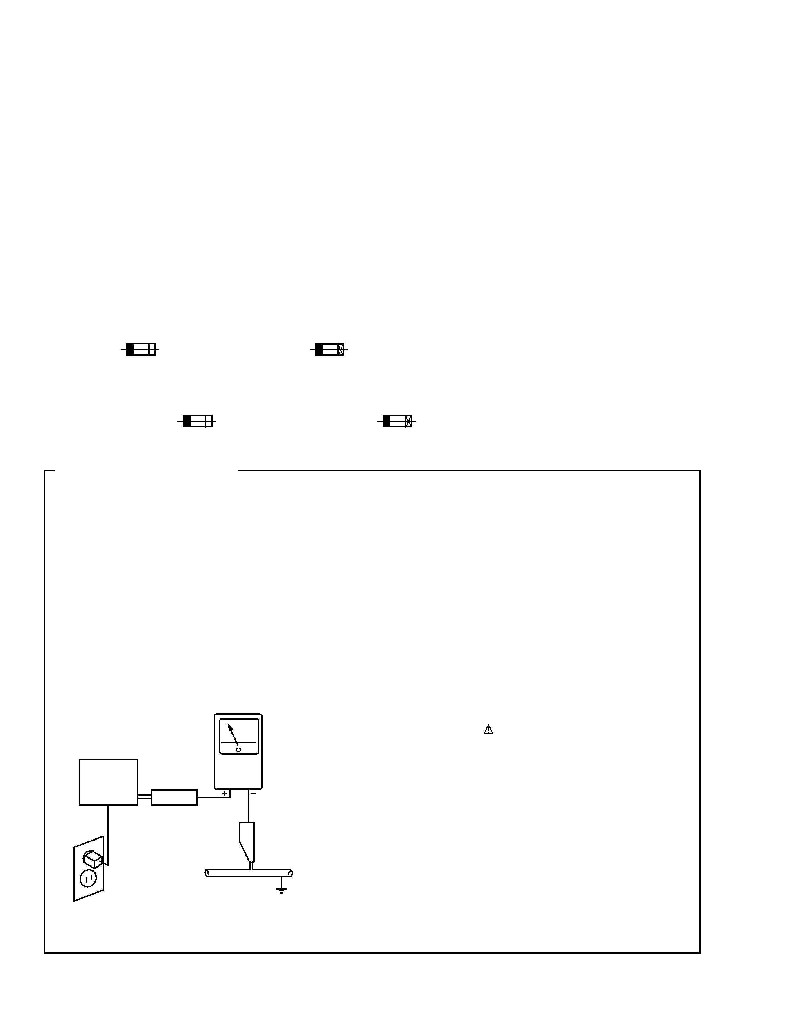
1. SAFETY PRECAUTIONS
The following check should be performed for the
continued protection of the customer and service
technician.
LEAKAGE CURRENT CHECK
Measure leakage current to a known earth ground (water
pipe, conduit, etc.) by connecting a leakage current tester
such as Simpson Model 229-2 or equivalent between the
earth ground and all exposed metal parts of the appliance
(input/output terminals, screwheads, metal overlays, control
shaft, etc.). Plug the AC line cord of the appliance directly
into a 120V AC 60Hz outlet and turn the AC power switch
on. Any current measured must not exceed 0.5mA.
(FOR USA MODEL ONLY)
Leakage
current
tester
Reading should
not be above
0.5mA
Device
under
test
Test all
exposed metal
surfaces
Also test with
plug reversed
(Using AC adapter
plug as required)
Earth
ground
AC Leakage Test
3
M-AX10
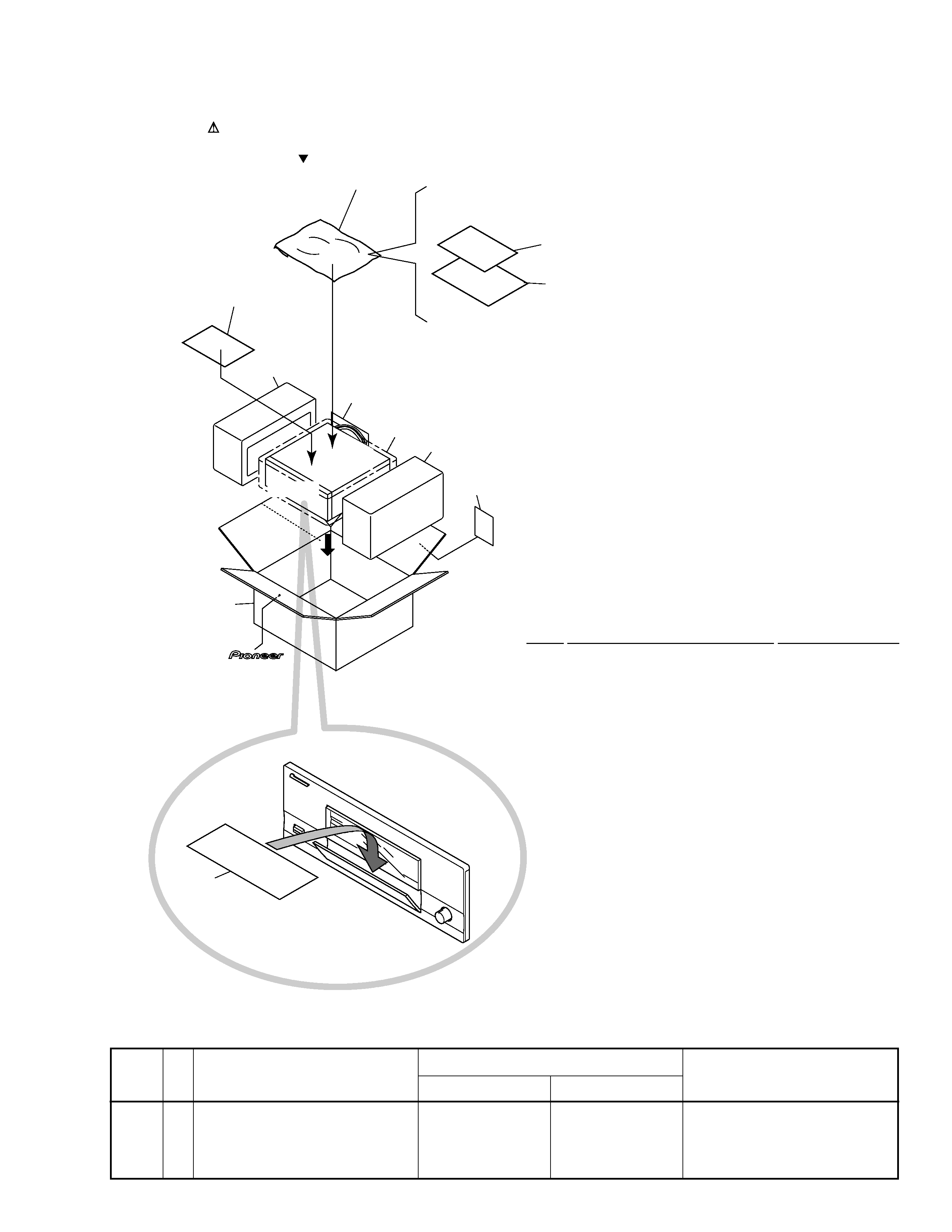
2.1 PACKING
NSP
1
Literature Bag
AHG-117
2
Instruction Manual (E)
ARB7217
NSP
3
Warranty Card
See Contrast table (2)
NSP
4
Warranty Card
See Contrast table (2)
5
Styrol Protector L
AHA9014
6
Styrol Protector R
AHA9015
7
Packing Case
See Contrast table (2)
8
Door Sheet
AHG7064
9
Mirror Mat
RHC1024
10
Polyester Bag
VHL1004
11
Recycle Label
See Contrast table (2)
(1) PACKING PARTS LIST
Mark No.
Description
Part No.
2. EXPLODED VIEWS AND PARTS LIST
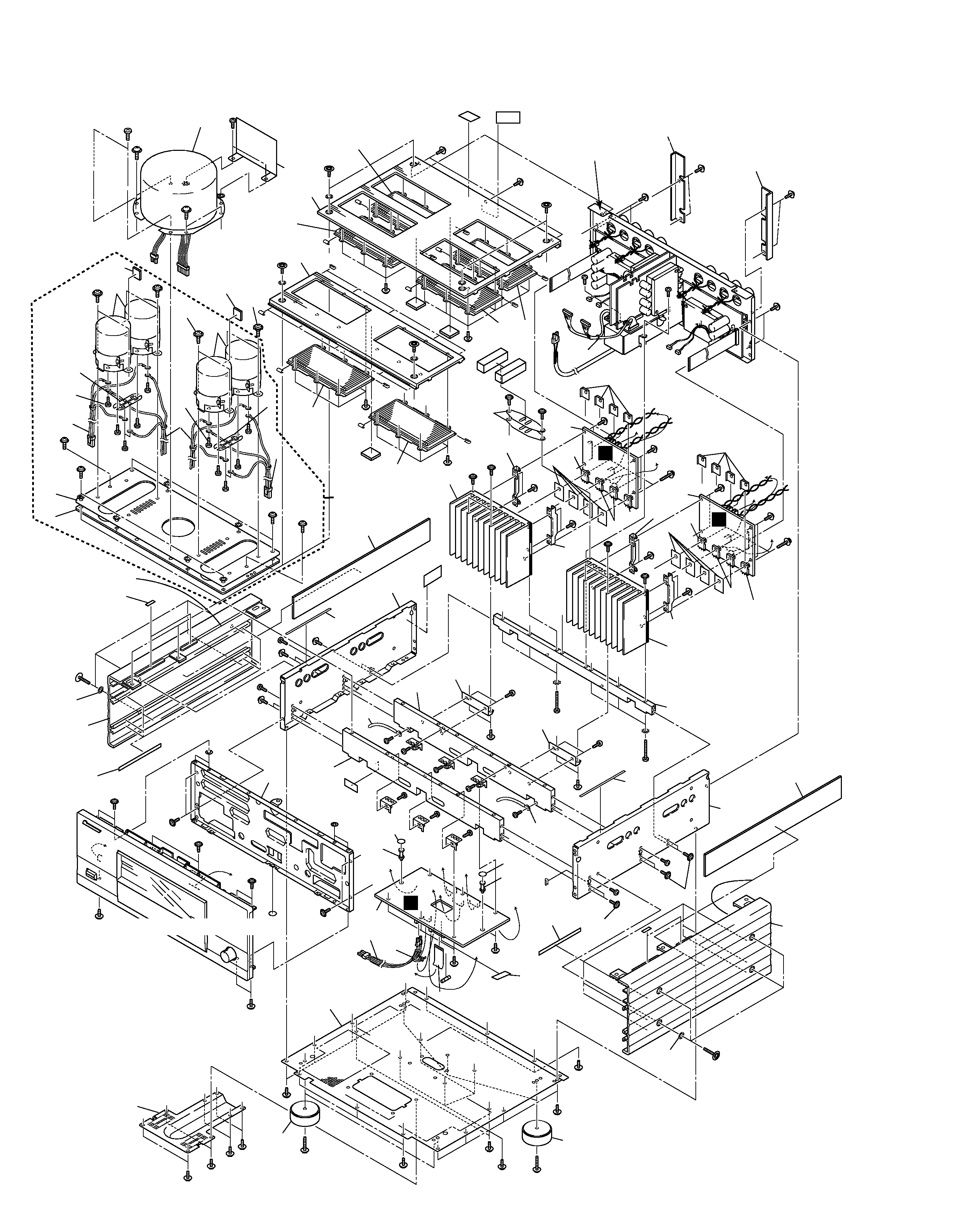
NOTES:
· Parts marked by "NSP" are generally unavailable because they are not in our Master Spare Parts List.
· The mark found on some component parts indicates the importance of the safety factor of the part.
Therefore, when replacing, be sure to use parts of identical designation.
· Screws adjacent to mark on the product are used for disassembly.
Mark
(2) CONTRAST TABLE
M-AX10/KU/CA and M-AX10/NY are constructed the same except for the following:
Part No.
Remarks
Symbol and Description
No.
NSP
3
Warranty Card
ARY7045
Not used
NSP
4
Warranty Card
Not used
ARY7022
7
Packing Case
AHD7875
AHD7874
11
Recycle Label
ARW7091
Not used
M-AX10/KU/CA
M-AX10/NY
FRONT
7
6
9
10
11
8
1
3
4
5
2
4
M-AX10
2.2 EXTERIOR
H
I
J
K
A
B
C
D
E
F
G
G
H
I
J
K
L
M
N
O
P
D
A B
C
F
E
H
I
J
K
L
M
N
O
Q
Q
P
7
77
77
49
68
90
89
45
39
67
39
67
39
39
39
39
49
42
45
45
62
42
62
39
39
36
36
32
32
73
73
73
73
73
64 83
for NY type
73
75
73
64
83
73
49
49
39
39
73
67
39
34
39
67
79
56
55
52
6
57
57
57
57
59
58
57
76
31
31
78
78
78
78
23
75
67
67
67
43
67
43
14
76
57
52
11
52
52
11
71
71
71
46
71
27
71
71
71
46
25
25
38
47
28
68
45
80
68
60
73
53
37
21
44
44
69
80
65
65
44
44
10
71
6
64
64
23
15
4
5
15
1
2
4
22
44
44
26
33
37
45
38
61
61
45
54
33
61
45
61
45
45
37
19
88
24
62
62
62
62
70
70
70
70
70
70
62
62
62
62
16
16
85
40
42
42
44
44
42
42
42
51
40
20
30
35
50
75
3
9
35
36
50
67
8
67
91
24
73
29
4
44
44
22
4
26
74
48
72
76
72
76
74
48
22
22
17
47
29
18
37
30
5
Refer to "2.4 FRONT PANEL"
73
73
73
34
34
Refer to "2.3 REAR PANEL"
Take care to the edge
when servicing
Take care to the edge
when sevicing
L
I
B
5
M-AX10
C
D
E
F
32
32
73
73
73
73
64
73
75
73
64
52
6
52
11
52
52
11
71
71
71
46
71
27
71
71
71
46
25
25
60
71
6
87
83
81
82
75
12
12
75
86
12
12
82
81
83
for KU type