ORDER NO.
PIONEER CORPORATION 4-1, Meguro 1-chome, Meguro-ku, Tokyo 153-8654, Japan
PIONEER ELECTRONICS (USA) INC. P.O. Box 1760, Long Beach, CA 90801-1760, U.S.A.
PIONEER EUROPE NV Haven 1087, Keetberglaan 1, 9120 Melsele, Belgium
PIONEER ELECTRONICS ASIACENTRE PTE. LTD. 253 Alexandra Road, #04-01, Singapore 159936
PIONEER CORPORATION 2008
KRP-SE01
ARP3516
T-ZZR SEP. 2008 Printerd in Japan
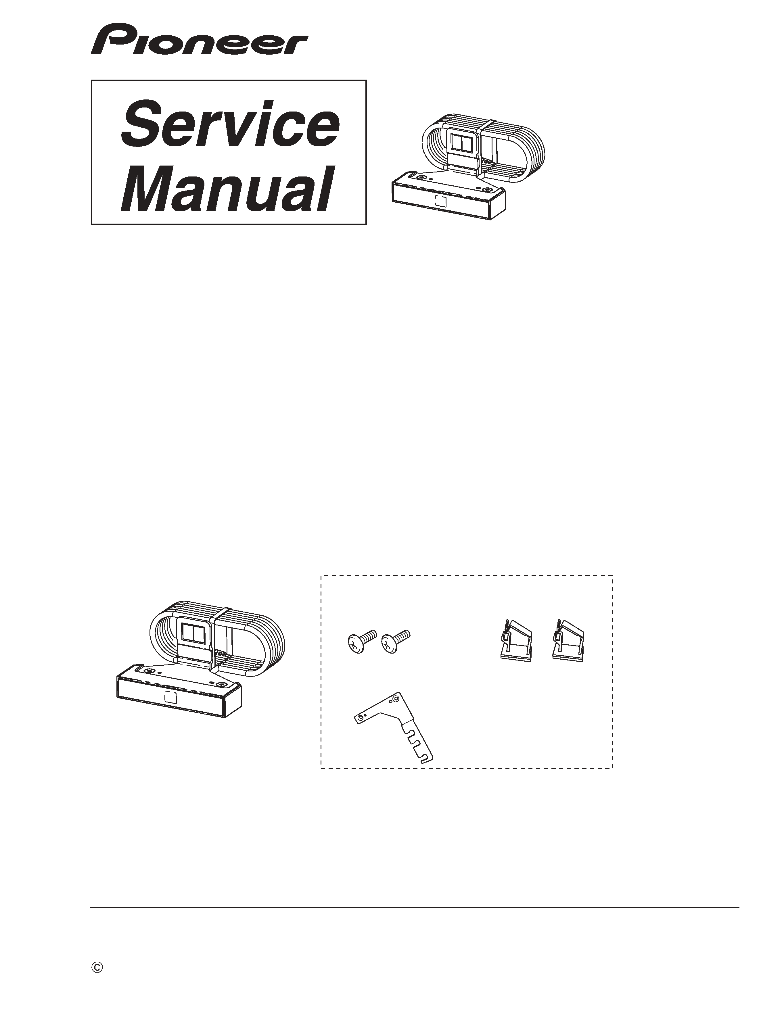
COLOR SENSOR
KRP-SE01
/XZC1/WL5
1.1 ACCESSORIES
· Color Sensor Module × 1
(AXF1196)
(AEC2169)
(JAP0002-880010)
(JAP0002-340010)
· Screw (M5 x 8 mm) × 2
· Cable Clamp × 2
· Color Sensor Bracket
1.2 SPECIFICATIONS
Weight :
KRP-SE01 .......................... 0.1 kg
Rated voltage :
KRP-SE01 .......................... DC5 V
Max.current consumption :
KRP-SE01 .......................... 50 mA or less
· Accessories
1. SPECIFICATIONS
KRP-SE01 /XZC1/CN5
NOTES :
· This is an optional color sensor dedicated for the KRP-500A/600A.
· For operation check of this product, it is necessary to connect it to the Display.
Operation check cannot be performed with this product alone.
2
KRP-SE01
12
3
4
C
D
F
A
B
E
1
23
4
2. EXPLODED VIEWS AND PARTS LIST
Parts marked by "NSP" are generally unavailable because they are not in our Master Spare Parts List.
The
mark found on some component parts indicates the importance of the safety factor of the part.
Therefore, when replacing, be sure to use parts of identical designation.
NOTES:
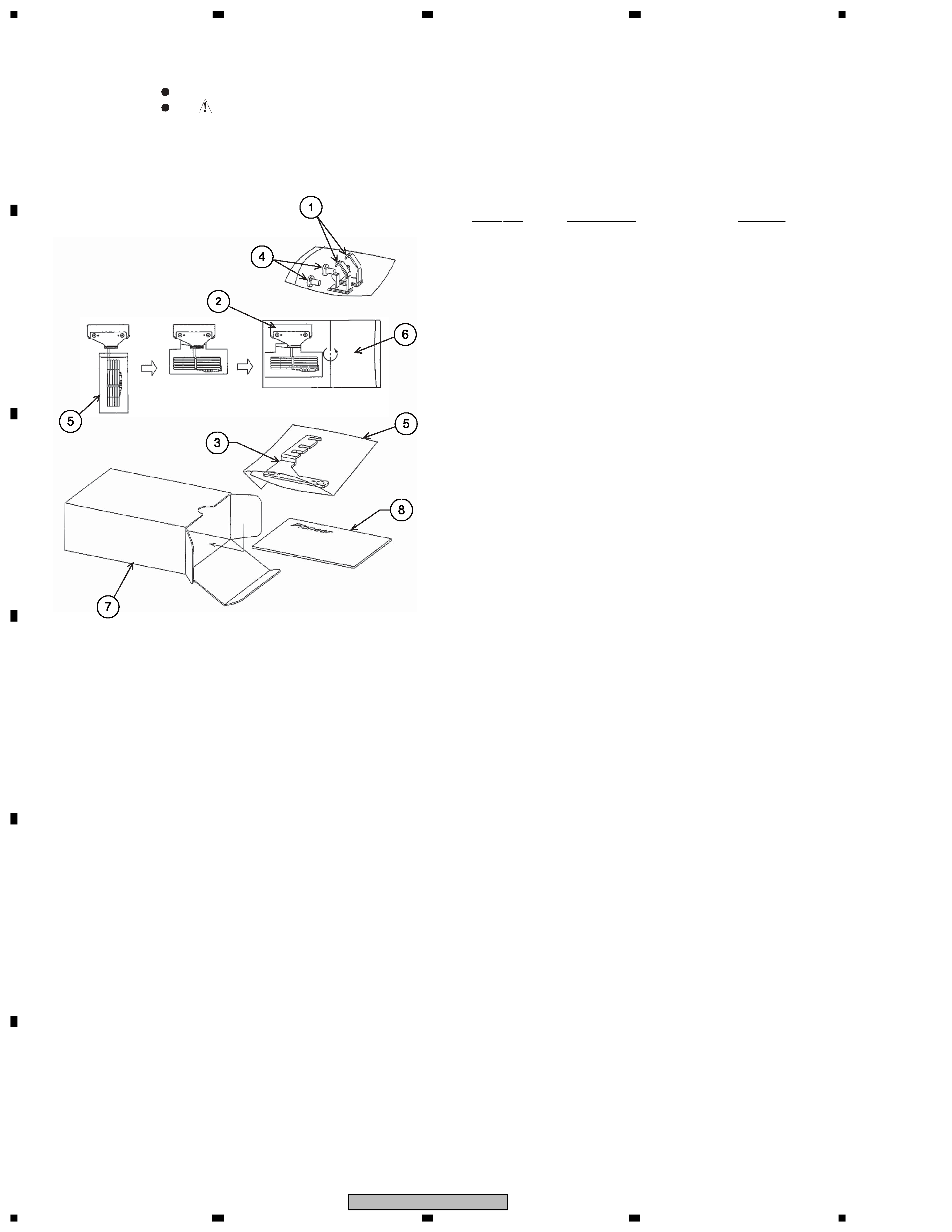
2.1 PACKING
1
Cable Clamp × 2
AEC2169
2
Color Sensor Module
AXF1196
(See "Parts Replacement.")
3
Color Sensor Bracket
JAP0002-340010
4
Screw (M5 x 8 mm) × 2
JAP0002-880010
5
Mirror Mat
JAP0002-890010
6
Air Capusle
JAP0002-890020
7
Packing Case
(for KRP-SE01/XZC1/WL5)
JAP0002-900040
(for KRP-SE01/XZC1/CN5)
JAP0002-900050
8
Operating Instructions
(for KRP-SE01/XZC1/WL5)
JAP0002-101010
(Japanese/English/French/Spanish/
German/Italian/Dutch/Russian)
8
Operating Instructions
(for KRP-SE01/XZC1/CN5)
JAP0002-101020
(Chinese)
PACKING Parts List
Mark No.
Description
Part No.
3. CONNECTION CHECK AND OPERATION
CHECK METHOD
· After connecting this color sensor to the Display, operation check can be performed with the methods described below.
In Normal Use
Check the indication for the color sensor on the "Optimum Performance" screen. In normal operation,"Enable" is displayed.
In Factory Mode
Check the CLS-RGB value and Status indication on the "PANEL WORKS" screen in Panel Factory mode.
(Before checking, set the "CLS" item for "ETC" to ON.) For details, refer to the service manual of the KRP-500P/600P.
4. PARTS REPLACEMENT
For replacement of the color sensor, use the Color Sensor Module (AXF1196) for replacement parts.
The Color Sensor Module (AXF1196) comprises the following parts:
·
Color sensor (×1)
·
Color sensor bracket (×1)
·
Screw (×2)
·
Cable clamp (×1)
·
Mirror mat (large) (×1)
·
Mirror mat (small) (×2)
Replace the parts, as required, and discard unnecessary parts.
The model name indicated on the label attached at the rear of the color sensor is "KRP-SE01" for merchandised products and
"AXF1196" for replacement parts. Although the indicated model names are different, they are the same product.