
Multi-CD control High power cassette player
with RDS tuner
Operation Manual
KEH-P2830R
KEH-P2800R

&RQWHQWV
Installation ............................................ 3
Installation with the rubber bush ........................ 3
Removing the Unit .............................................. 3
Connection Diagram ............................ 4
Connecting the Units ........................... 6
Key Finder ............................................ 7
Before Using This Product .................. 8
About This Product ............................................. 8
About This Manual ............................................. 8
Precaution ........................................................... 8
In Case of Trouble .............................................. 8
Detaching and Replacing the
Front Panel ........................................... 9
Theft Protection .................................................. 9
Initial Setting Menu ............................ 10
Entering the Initial Setting Menu ..................... 10
Changing the FM Tuning Step ......................... 10
Switching the Auto PI Seek .............................. 11
Basic Operation ................................. 12
Switching Power On ......................................... 12
Switching Power Off ........................................ 12
Tuner Operation ................................. 13
Basic Operation of Tuner ................................. 13
AF Function Switching ..................................... 14
Entering the Function Menu ............................. 15
Local Seek Tuning ............................................ 16
Preset Tuning .................................................... 16
BSM (Best Stations Memory) .......................... 17
Preset Memory .................................................. 17
Recalling Preset Stations .................................. 18
Using the Programmable Button ...................... 18
Using RDS Functions ........................ 20
What is RDS? ................................................... 20
Program Service Name Display ....................... 20
AF Function ..................................................... 21
PI Seek Function .............................................. 22
REG Function ................................................... 22
TA Function ..................................................... 23
PTY Function ................................................... 25
Using the Cassette Player ................. 28
Basic Operation of Cassette Player .................. 28
Fast Forward/Rewind ....................................... 29
Entering the Function Menu ............................. 29
Radio Intercept ................................................. 30
Cassette Player and Care .................. 31
Precaution ......................................................... 31
Cleaning the Head ........................................... 31
Audio Adjustment .............................. 32
Selecting the Mode ........................................... 32
Balance Adjustment ......................................... 32
Bass/Treble Adjustment ................................... 33
Loudness Adjustment ....................................... 33
Other Functions ................................. 34
Time Display/Setting ....................................... 34
Specifications .................................... 35
,QVWDOODWLRQ
1RWH
· Before finally installing the unit, connect the wiring temporarily, making sure it is all connected up
properly, and the unit and the system work properly.
· Use only the parts included with the unit to ensure proper installation. The use of unauthorized parts
can cause malfunctions.
· Consult with your nearest dealer if installation requires the drilling of holes or other modifications of
the vehicle.
· Install the unit where it does not get in the driver's way and cannot injure the passenger if there is a
sudden stop, like an emergency stop.
· If installation angle exceeds 30° from horizontal, the unit might not give its optimum performance.
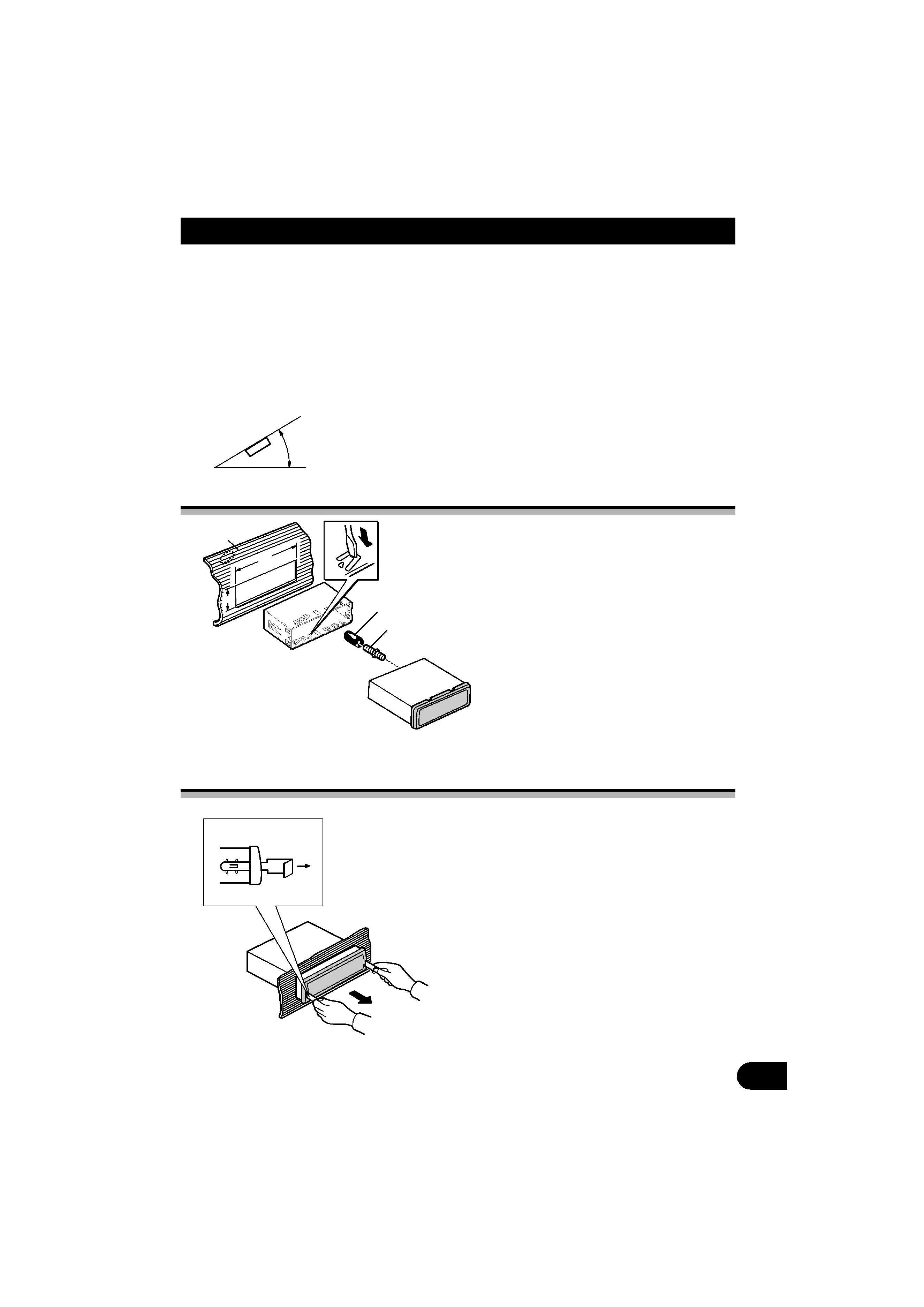
Installation with the rubber bush
Removing the Unit
30°
182
53
1
2
3
4
1. Dashboard
2. Holder
After inserting the holder into the dashboard,
then select the appropriate tabs according to
the thickness of the dashboard material and
bend them.
(Install as firmly as possible using the top
and the bottom tabs. To secure, bend the tabs
90 degrees.)
3. Rubber bush
4. Screw
5
5. Insert the supplied extraction keys into the
unit, as shown in the figure, until they click
into place. Keeping the keys pressed against
the sides of the unit, pull the unit out.
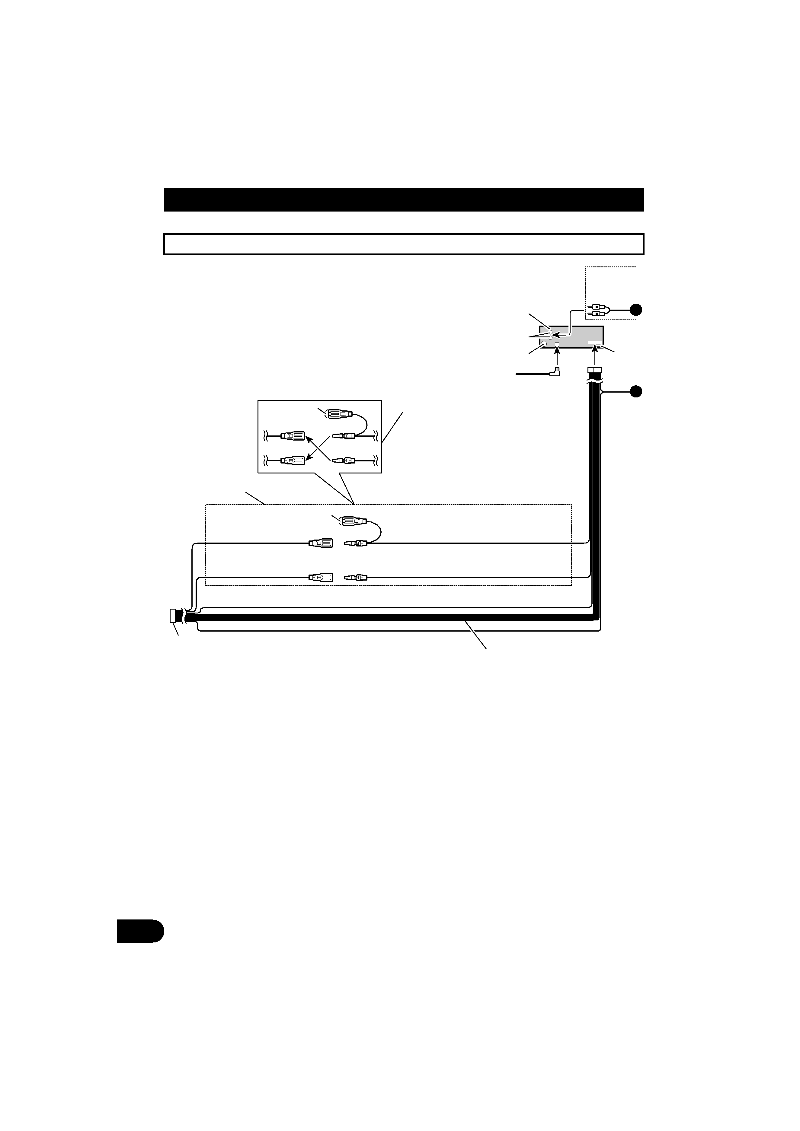
&RQQHFWLRQ 'LDJUDP
This product conforms to new cord colors.
1
3
2
4
5
7
8
9
10
11
7
8
9
10
11
6
13
14
12
15
A
B
1. This unit
2. Rear output
3. Anntenna jack
4. Multi-CD player (sold separately)
5. Connect leads of the same color to each other.
6.
1RWH
· Depending on the kind of vehicle, the function
of 9 and 11 may be different. If this is the case,
be sure to connect 8 to 11 and 9 to 10.
· When the power cord of a component such as
a Multi-CD Player is connected to this unit's
power cord, check that 9 and 11 (Back-up or
Accessory) are operating correctly, and that
connections are correct.
7. Cap
8. Yellow
To terminal always supplied with power
regardless of ignition switch position.
9. Yellow
Back-up (or accessory)
10. Red
To electric terminal controlled by ignition switch
(12 V DC) ON/OFF.
11. Red
Accessory (or Back-up)
12. Black (ground)
To vehicle (metal) body.
13. ISO connector
1RWH
· In some vehicles, the ISO connector may be
divided into two. If this is the case, be sure to
connect to both connectors.
16
17
18
19
20
21
22
23
23
24
A
B
CAUTION
Cords for this product
and those for other
products may be
different colors even if
they have the same
function. When
connecting this product
to another product, refer
to the supplied
Installation manuals of
both products and
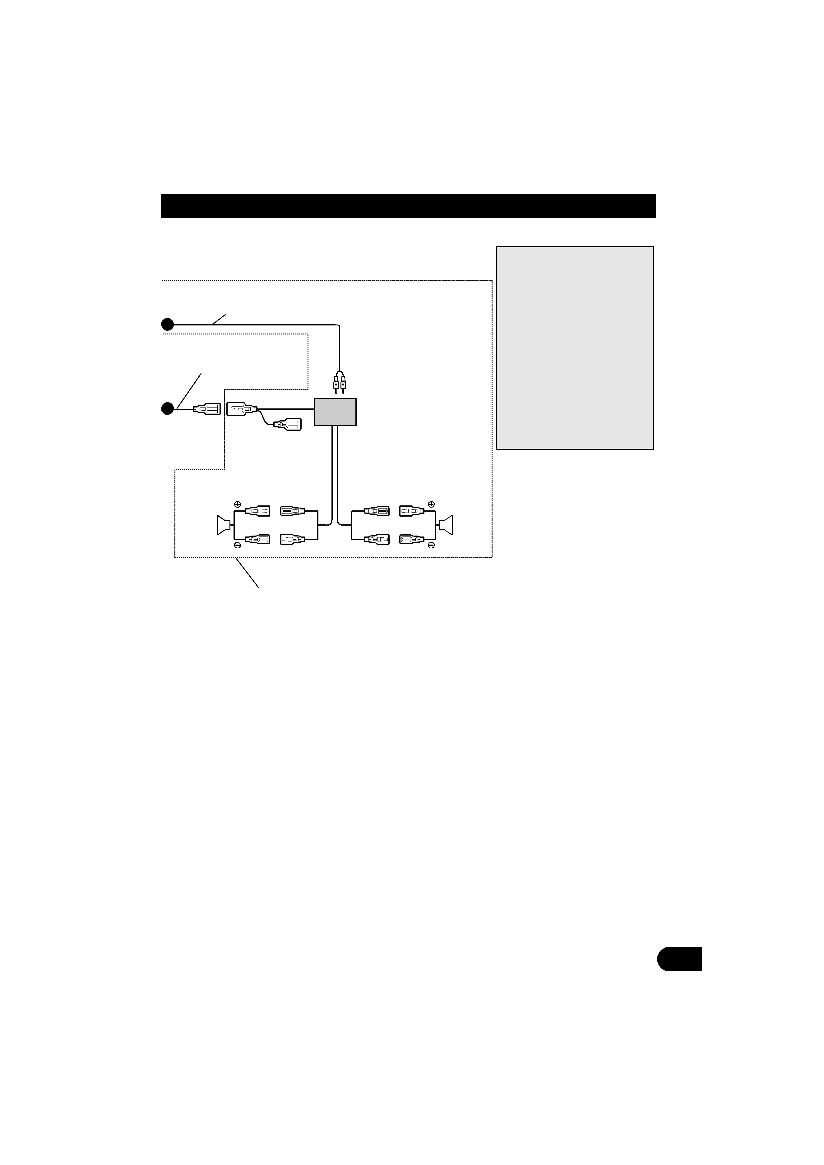
14. Speaker leads
White: Front left
White/black: Front left
Ã
Gray: Front right
Gray/black: Front right
Green: Rear left
Green/black: Rear left
Violet: Rear right
Violet/black: Rear right
15. Fuse
16. Connecting cords with RCA pin plugs (sold
separately).
17. Blue/white
18. System remote control
19. To system control terminal of the power amp or
Auto-antenna relay control terminal.
(Max. 300 mA 12 V DC.)
20. Power amp (sold separately)
21. Left speaker
22. Right speaker
23. Rear
24. Use this for connections when you have the
separately available amplifier.