ORDER NO.
PIONEER ELECTRONIC CORPORATION 4-1, Meguro 1-Chome, Meguro-ku, Tokyo 153-8654, Japan
PIONEER ELECTRONICS SERVICE, INC. P.O. Box 1760, Long Beach, CA 90801-1760, U.S.A.
PIONEER ELECTRONIC (EUROPE) N.V. Haven 1087, Keetberglaan 1, 9120 Melsele, Belgium
PIONEER ELECTRONICS ASIACENTRE PTE. LTD. 253 Alexandra Road, #04-01, Singapore 159936
PIONEER ELECTRONIC CORPORATION 1999
HTZ-7
DVD SURROUND SYSTEM
RRV2111
TZZY FEB. 1999 Printed in Japan
HTZ-C7
HTZ-SW7, HTZ-ST7
DVD CENTER UNIT
POWERED SUBWOOFER
THIS MANUAL IS APPLICABLE TO THE FOLLOWING MODEL(S) AND TYPE(S).
Type
Model
HTZ-7
Power Requirement
Remarks
MY
AC220- 230V
1. SAFETY INFORMATION ....................................... 2
2. EXPLODED VIEWS AND PARTS LIST ................... 4
3. SCHEMATIC DIAGRAM ...................................... 21
4. PCB CONNECTION DIAGRAM ............................ 56
5. PCB PARTS LIST ................................................ 81
6. ADJUSTMENT .................................................... 92
7. GENERAL INFORMATION ................................ 101
7.1 PARTS ........................................................ 101
7.1.1 IC .......................................................... 101
7.1.2 DISPLAY ............................................... 107
This product is a system(s) component.
This product does not function properly when independent; to avoid malfunctions, be sure
to connect it to the prescribed system component(s), otherwise damage may result.
HTZ-7 is a combination of the following components.
DVD SURROUND SYSTEM (HTZ-7)
DVD CENTER UNIT (HTZ-C7)
POWERED SUBWOOFER (HTZ-SW7)
AMP ASSY (A-SW7)
SATELLITE SPEAKER (HTZ-ST7)
CONTENTS
7.2 DIAGNOSIS ................................................. 108
7.2.1 FAIL-SAFE ............................................ 108
7.2.2 SINGLE UNIT OPERATION METHODS .. 109
7.2.3 DISASSEMBLY ..................................... 111
7.2.4 TEST MODE ......................................... 116
7.3 BLOCK DIAGRAM ....................................... 120
7.4 REMOTE CONTROL UNIT ........................... 122
7.4.1 EXPLODED VIEWS AND PARTS LIST ... 122
7.4.2 SCHEMATIC DIAGRAM ......................... 124
8. PANEL FACILITIES AND SPECIFICATIONS ...... 125
SATELLITE SPEAKER
HTZ-7, HTZ-C7, HTZ-SW7, HTZ-ST7
2
(FOR USA MODEL ONLY)
1. SAFETY INFORMATION
1. SAFETY PRECAUTIONS
The following check should be performed for the
continued protection of the customer and service
technician.
ANY MEASUREMENTS NOT WITHIN THE LIMITS
OUTLINED ABOVE ARE INDICATIVE OF A PO-
TENTIAL SHOCK HAZARD AND MUST BE COR-
RECTED BEFORE RETURNING THE APPLIANCE
TO THE CUSTOMER.
2. PRODUCT SAFETY NOTICE
Many electrical and mechanical parts in the appli-
ance have special safety related characteristics. These
are often not evident from visual inspection nor the
protection afforded by them necessarily can be ob-
tained by using replacement components rated for
voltage, wattage , etc.
Replacement parts which have
these special safety
characteristics are identified in
this Service Manual.
Electrical components having such features are
identified by marking with a
on the schematics and
on the parts list in this Service Manual.
The use of a substitute replacement component which
does not have the same safety characteristics as the
PIONEER recommended replacement one, shown in
the parts list in this Service Manual, may create shock,
fire, or other hazards.
Product Safety is continuously under review and
new instructions are issued from time to time. For
the latest information, always consult the current
PIONEER Service Manual. A subscription to, or
ad-
ditional copies of, PIONEER Service Manual may be
obtained at a nominal charge from PIONEER.
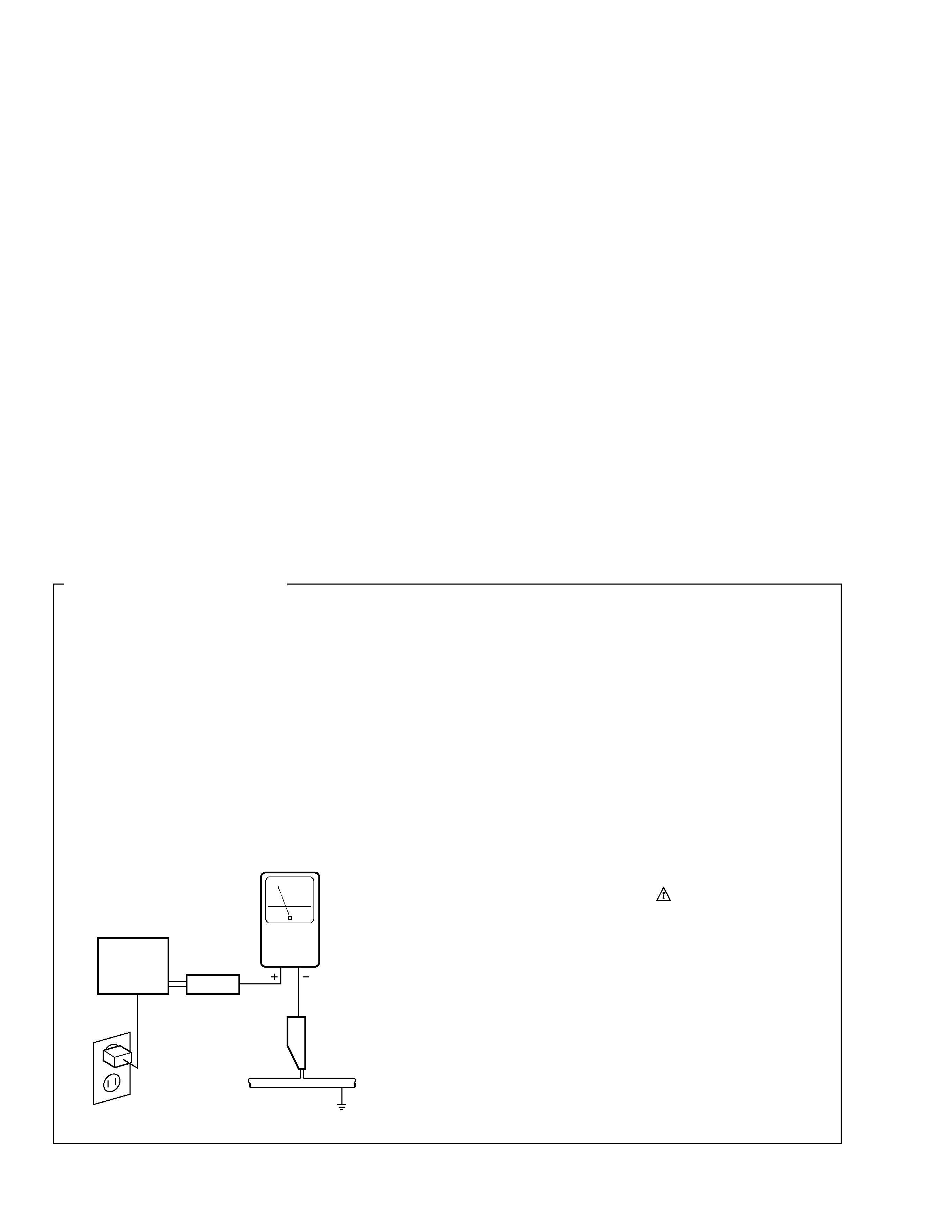
LEAKAGE CURRENT CHECK
Measure leakage current to a known earth ground
(water pipe, conduit, etc.) by connecting a leakage
current tester such as Simpson Model 229-2 or
equivalent between the earth ground and all exposed
metal parts of the appliance (input/output terminals,
screwheads, metal overlays, control shaft, etc.). Plug
the AC line cord of the appliance directly into a 120V
AC 60 Hz outlet and turn the AC power switch on. Any
current measured must not exceed 0.5 mA.
Also test with plug
reversed
(Using AC adapter
plug as required)
Device
under
test
Test all exposed
metal surfaces
Earth ground
Leakage
current
tester
Reading should
not be above
0.5 mA
AC Leakage Test
This service manual is intended for qualified service technicians; it is not meant for the casual
do-it-yourselfer. Qualified technicians have the necessary test equipment and tools, and have been
trained to properly and safely repair complex products such as those covered by this manual.
Improperly performed repairs can adversely affect the safety and reliability of the product and may
void the warranty. If you are not qualified to perform the repair of this product properly and safely, you
should not risk trying to do so and refer the repair to a qualified service technician.
WARNING
This product contains lead in solder and certain electrical parts contain chemicals which are known to the state of California to
cause cancer, birth defects or other reproductive harm.
Health & Safety Cod e Section 25249.6 Proposition 65
HTZ-7, HTZ-C7, HTZ-SW7, HTZ-ST7
3
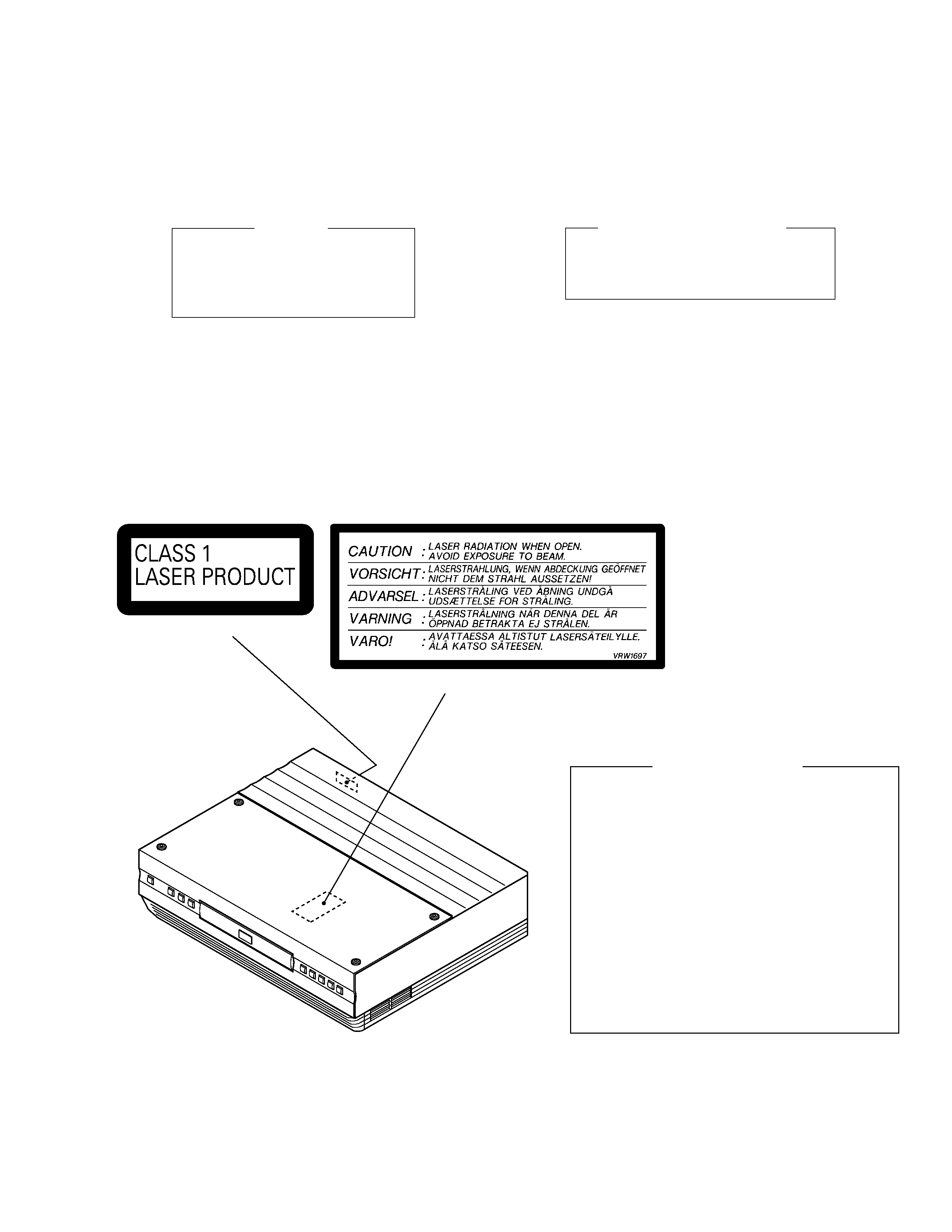
IMPORTANT
THIS PIONEER APPARATUS CONTAINS
LASER OF CLASS 1.
SERVICING OPERATION OF THE APPARATUS
SHOULD BE DONE BY A SPECIALLY
INSTRUCTED PERSON.
LASER DIODE CHARACTERISTICS
FOR DVD : MAXIMUM OUTPUT POWER : 7 mW
WAVELENGTH : 650 nm
FOR CD :
MAXIMUM OUTPUT POWER : 5mW
WAVELENGTH : 780 785 nm
LABEL CHECK
Additional Laser Caution
1. Inside detection switch (S201 on the INSB assy) and loading-
status detection switch (S301 on the LOSB assy) are detected
by the microprocessor (IC501 in the DVDM assy).
· To permit the laser diode to oscillate, it is required to set the
inside detection switch for the inside position (S201 : ON) and to
set the loading-status detection switch for the clamp position (the
center terminal of S301 is shorted to +5V). The laser diode
oscillation will continue if pin 13 of IC101 is shorted to +5V (fault
condition) in the DVDM assy.
In the test mode
, the laser diode oscillates when microproces-
sor detects a PLAY signal, or when the PLAY key is pressed
(S5901 ON in the FRONT(1) assy), with the above requirements
satisfied.
2. When the cover is open, close viewing through the objective lens
with the naked eye will cause exposure to the laser beam.
: Refer to page 94.
( Printed on the Rear Panel )
( FCC Holder Top )
HTZ-7, HTZ-C7, HTZ-SW7, HTZ-ST7
4
1
3
16
17
2
4
5
8
11
14
12
13
19
10
18
15
6
7
9
Refer to " 7.4 REMOTE
CONTROL UNIT ".
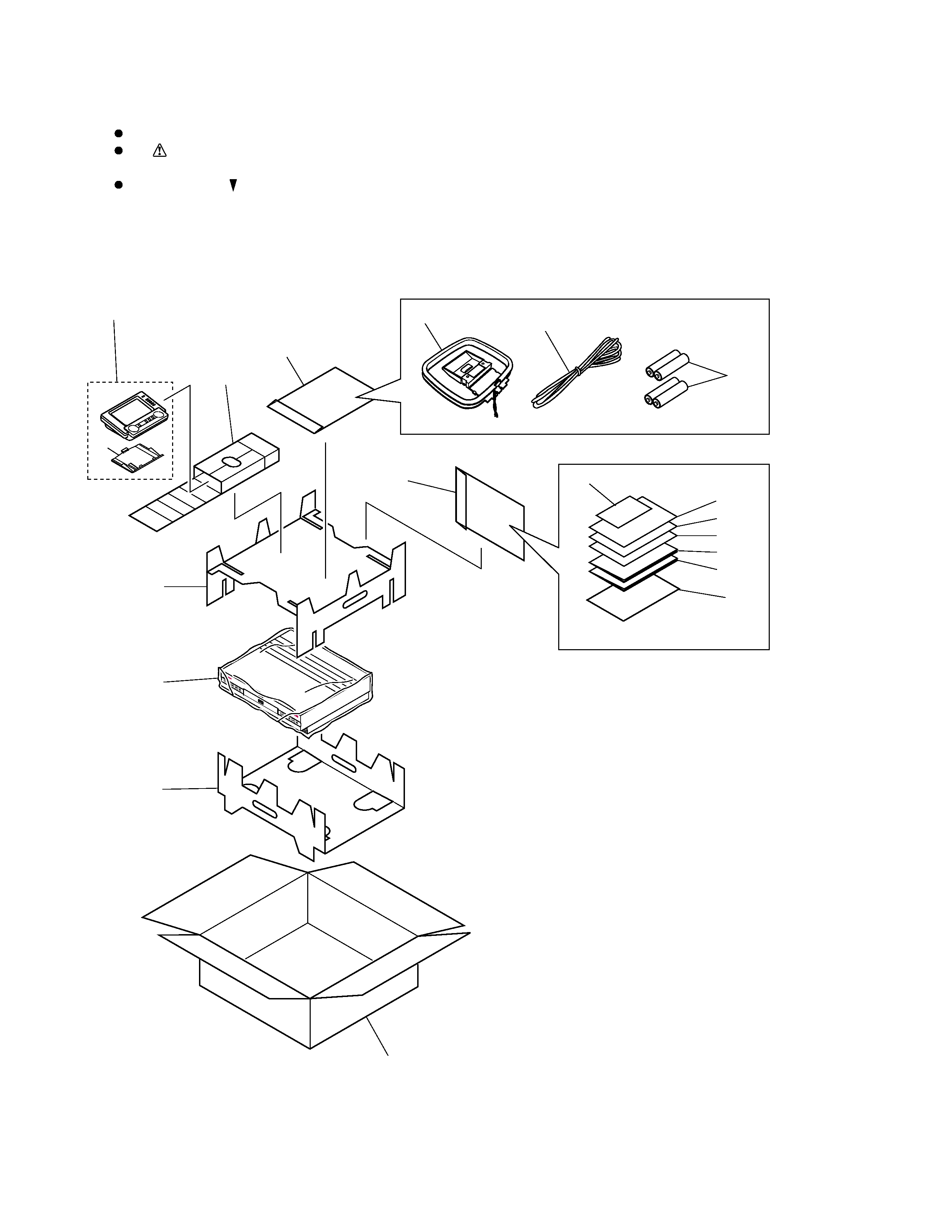
2. EXPLODED VIEWS AND PARTS LIST
2.1 DVD CENTER UNIT (HTZ-C7)
2.1.1 PACKING
NOTES :
Parts marked by " NSP " are generally unavailable because they are not in our Master Spare Parts List.
The
mark found on some component parts indicates the importance of the safety factor of the part.
Therefore, when replacing, be sure to use parts of identical designation.
Screw adjacent to
mark on the product are used for disassembly.

HTZ-7, HTZ-C7, HTZ-SW7, HTZ-ST7
5
1
Protector A
AHA7242
2
Protector B
AHA7257
3
Protector C
AHA7244
4
Packing Case
AHD7772
5
Packing Sheet (750
× 600 × 0.5) Z23007
6
Operating Instructions
ARE7230
(Setting up the HTZ7)
(English/French/German/Italian)
7
Operating Instructions
ARE7231
(Setting up the HTZ7)
(Dutch/Spanish/Swedish)
8
Operating Instructions
ARE7218
(Basic/Detailed) (English/French)
9
Operating Instructions
ARE7226
(Basic/Detailed)
(Italian/German)
10
Operating Instructions
ARE7227
(Basic/Detailed)
(Dutch/Spanish/Swedish)
11
FM Antenna
ADH7005
12
AM Loop Antenna
ATB7009
13
Remote Control (CUHT005)
AXD7232
NSP
14
Alkaline Batteries (AA/LR6)
VEM1012
NSP
15
Warranty
ARY7022
16
Polyethylene Bag
Z21038
(0.03
× 230 × 340)
NSP
17
Polyethylene Bag
Z21040
(0.1
× 350 × 440)
18
Protector E
AHA7258
19
Battery Cover
103RRC14701R
PACKING PARTS LIST
Mark No.
Description
Part No.