ORDER NO.
PIONEER CORPORATION 4-1, Meguro 1-chome, Meguro-ku, Tokyo 153-8654, Japan
PIONEER ELECTRONICS SERVICE, INC. P.O. Box 1760, Long Beach, CA 90801-1760, U.S.A.
PIONEER ELECTRONIC (EUROPE) N.V. Haven 1087, Keetberglaan 1, 9120 Melsele, Belgium
PIONEER ELECTRONICS ASIACENTRE PTE. LTD. 253 Alexandra Road, #04-01, Singapore 159936
PIONEER CORPORATION 1999
c
HTP-55
RRV2164
T IZE OCT. 1999 Printed in Japan
Type
Model
Power Requirement
HTP-55
SDXCN1
AC110V/120-127V/220V/240V
With the voltage selector
THIS MANUAL IS APPLICABLE TO THE FOLLOWING MODEL(S) AND TYPE(S).
HOME THEATER SYSTEM
1. SAFETY INFORMATION ...................................... 2
2. EXPLODED VIEWS AND PARTS LIST ............... 3
3. BLOCK DIAGRAM AND SCHEMATIC DIAGRAM ..... 6
4. PCB CONNECTION DIAGRAM ......................... 17
5. PCB PARTS LIST ............................................... 22
6. ADJUSTMENT .................................................... 24
CONTENTS
7. GENERAL INFORMATION ................................ 26
7.1 PARTS .......................................................... 26
7.1.1 IC ............................................................ 26
7.1.2 DISPLAY ................................................. 33
8. PANEL FACILITIES AND SPECIFICATIONS ....... 35
The voltage can be converted by
the following method.
Component
Model
Service Manual
Remarks
HTP-55/SDXCN1
AUDIO MULTI-CHANNEL RECEIVER
(VSX-108/SDXCN1)
This manual
REAR SPK. BOX&LABEL
SP108250297S
SUBWOOFER BOX&LABEL
SP10830001S
FRONT SPK. BOX&LABEL
SP108400297AS
CENTER SPK. BOX&LABEL
SP108401297BS
The HTP-55 is a combination of the components in the Table below.
2
HTP-55
1. SAFETY INFORMATION
This service manual is intended for qualified service technicians ; it is not meant for the casual do-it-
yourselfer. Qualified technicians have the necessary test equipment and tools, and have been trained
to properly and safely repair complex products such as those covered by this manual.
Improperly performed repairs can adversely affect the safety and reliability of the product and may
void the warranty. If you are not qualified to perform the repair of this product properly and safely, you
should not risk trying to do so and refer the repair to a qualified service technician.
WARNING
This product contains lead in solder and certain electrical parts contain chemicals which are known to the state of California to cause
cancer, birth defects or other reproductive harm.
Health & Safety Code Section 25249.6 Proposition 65
NOTICE
(FOR CANADIAN MODEL ONLY)
Fuse symbols
(fast operating fuse) and/or
(slow operating fuse) on PCB indicate that replacement parts must
be of identical designation.
REMARQUE
(POUR MODÈLE CANADIEN SEULEMENT)
Les symboles de fusible
(fusible de type rapide) et/ou
(fusible de type lent) sur CCI indiquent que les pièces
de remplacement doivent avoir la même désignation.
ANY MEASUREMENTS NOT WITHIN THE LIMITS
OUTLINED ABOVE ARE INDICATIVE OF A POTENTIAL
SHOCK HAZARD AND MUST BE CORRECTED BEFORE
RETURNING THE APPLIANCE TO THE CUSTOMER.
2. PRODUCT SAFETY NOTICE
Many electrical and mechanical parts in the appliance
have special safety related characteristics. These are
often not evident from visual inspection nor the protection
afforded by them necessarily can be obtained by using
replacement components rated for voltage, wattage, etc.
Replacement parts which have these special safety
characteristics are identified in this Service Manual.
Electrical components having such features are identified
by marking with a
on the schematics and on the parts list
in this Service Manual.
The use of a substitute replacement component which does
not have the same safety characteristics as the PIONEER
recommended replacement one, shown in the parts list in
this Service Manual, may create shock, fire, or other hazards.
Product Safety is continuously under review and new
instructions are issued from time to time. For the latest
information, always consult the current PIONEER Service
Manual. A subscription to, or additional copies of, PIONEER
Service Manual may be obtained at a nominal charge from
PIONEER.
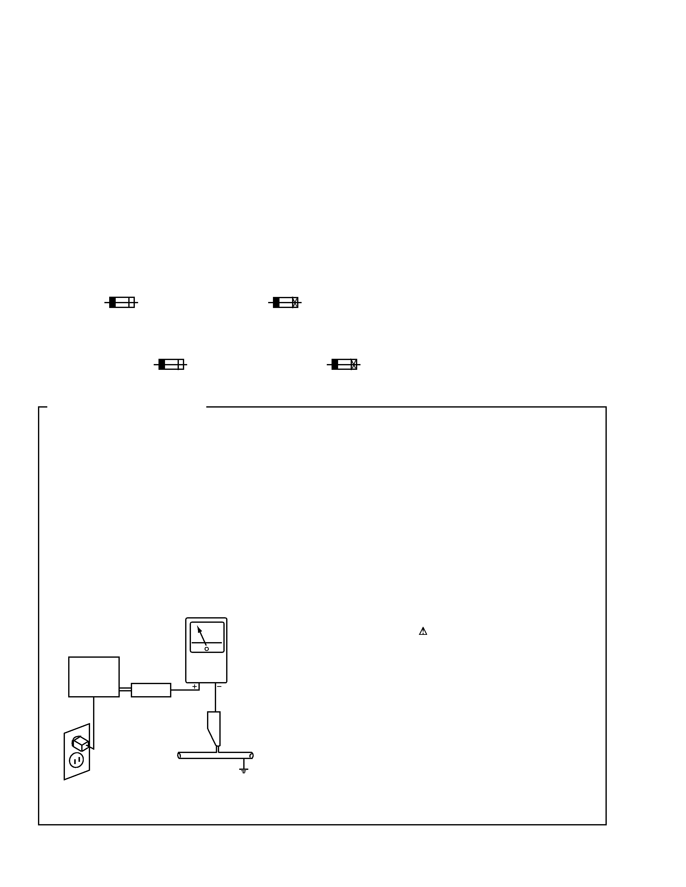
1. SAFETY PRECAUTIONS
The following check should be performed for the
continued protection of the customer and service
technician.
LEAKAGE CURRENT CHECK
Measure leakage current to a known earth ground (water
pipe, conduit, etc.) by connecting a leakage current tester
such as Simpson Model 229-2 or equivalent between the
earth ground and all exposed metal parts of the appliance
(input/output terminals, screwheads, metal overlays, control
shaft, etc.). Plug the AC line cord of the appliance directly
into a 120V AC 60Hz outlet and turn the AC power switch
on. Any current measured must not exceed 0.5mA.
(FOR USA MODEL ONLY)
Leakage
current
tester
Reading should
not be above
0.5mA
Device
under
test
Test all
exposed metal
surfaces
Also test with
plug reversed
(Using AC adapter
plug as required)
Earth
ground
AC Leakage Test
3
HTP-55
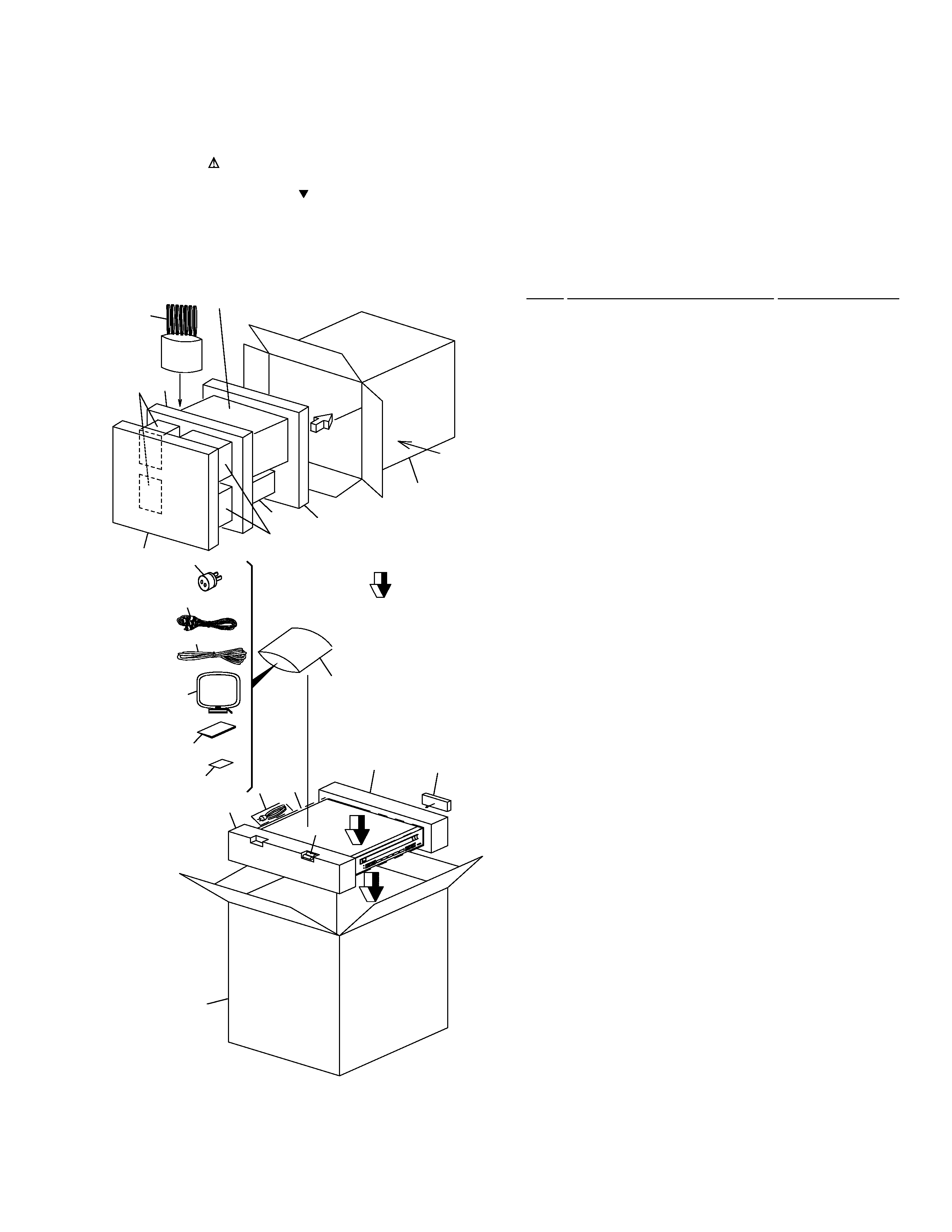
2.1 PACKING
· PACKING PARTS LIST
Mark No.
Description
Part No.
2. EXPLODED VIEWS AND PARTS LIST
NOTES:
· Parts marked by "NSP" are generally unavailable because they are not in our Master Spare Parts List.
· The mark found on some component parts indicates the importance of the safety factor of the part.
Therefore, when replacing, be sure to use parts of identical designation.
· Screws adjacent to mark on the product are used for disassembly.
1
AM Loop Antenna
01582100001S
2
FM Antenna
06410001003S
3
Operating Instructions
152205521297
(English, Spanish)
4
Polyform L
14901081000S
5
Polyform R
14901082000S
6
Remote Control Unit
18201080001S
7
HTP-55SD/Carton Box
151205510297
8
Poly. Bag (4
× 20)
15004011210S
9
Poly. Bag (10
× 15)
15010015510S
10
Poly. Bag (20
× 26)
15020026510S
11
RCA Cable
PDE1248
NSP
12
Dry Cell Battery (LR6, AA)
· · · · ·
NSP
13
Warranty Card
· · · · ·
14
Speaker Cord Set
SP108SPKWIRE
15
Rear SPK. Box&Label
SP108250297S
16
Subwoofer Box&Label
SP10830001S
17
Front SPK. Box&Label
SP108400297AS
18
Center SPK. Box&Label
SP108400297BS
19
AC Adapter Plug
02430000008S
20
VSX108SPK. Polyform
14901080000S
21
VSX108SPK. Polyform
14901083000S
22
VSX108SPK. Polyform
14901084000S
23
S-HTP-55 SPK. Carton Box
15340552000S
FRONT
2
11
14
23
22
21
19
18
17
15
20
16
Refer to "2.3 SUBWOOFER BOX&LABEL".
1
4
10
8
9
12
7
6
3
13
5
4
HTP-55
A
A
4
25
25
20
5
27
29
3
25
Bottom Cover
25
25
25
25
25
22
22
25
18
19
19
17
19
7
25
25
25
25
25
25
25
6
14
15
12
13
11
10
30
9
24
26
26
25
25
34
25
35
8
25
25
2
28
25
33
36
31
25
25
32
28
28
23
25
25
25
25
25
21
1
25
25
26
26
26
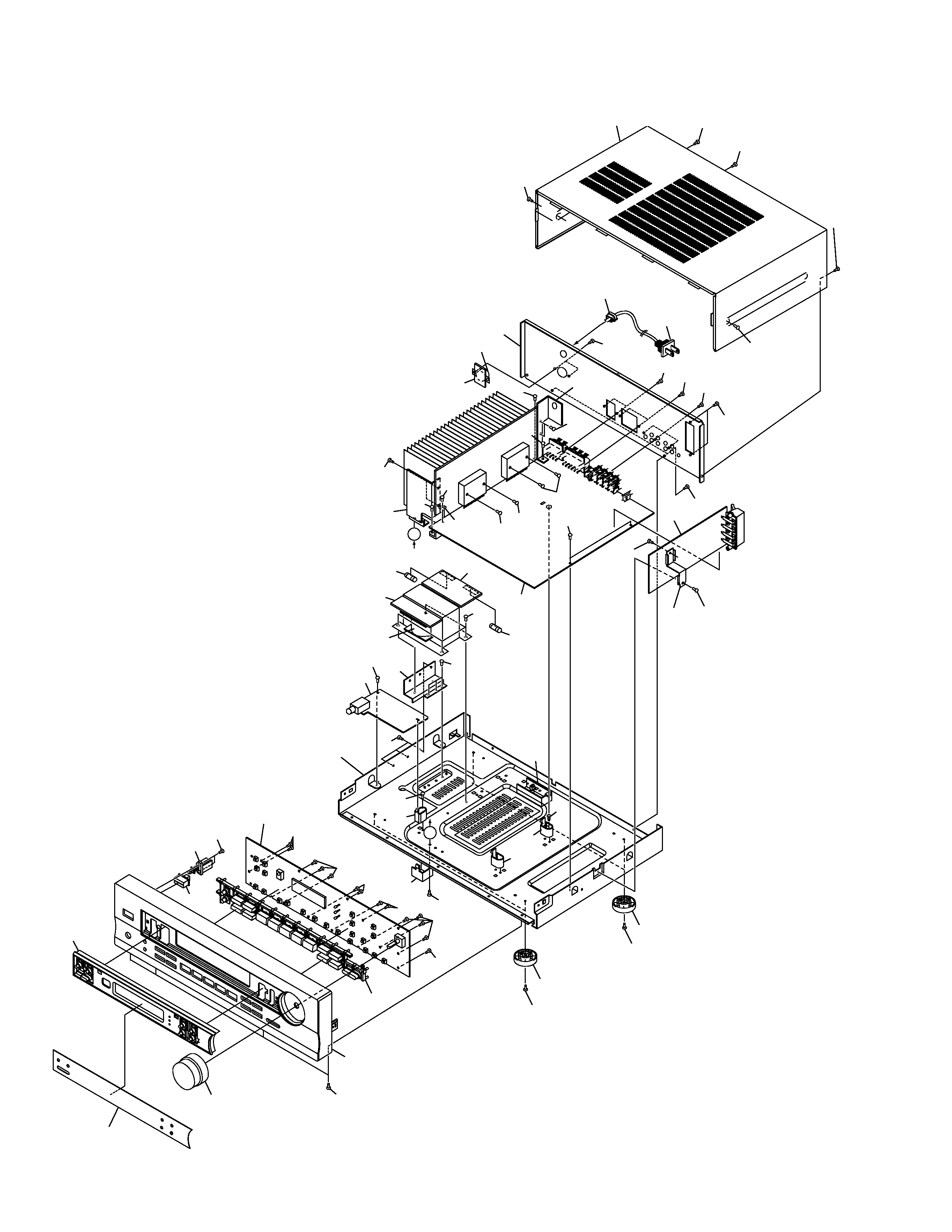
2.2 EXTERIOR
5
HTP-55
· EXTERIOR PARTS LIST
Mark No.
Description
Part No.
NSP
1
TUNER PCB
AZW7259
(Circuit Parts Assy)
NSP
2
MAIN PCB
AZW7259
(Circuit Parts Assy)
NSP
3
PHONE PCB
AZW7259
(Circuit Parts Assy)
NSP
4
AC O/P PCB
AZW7259
(Circuit Parts Assy)
NSP
5
AC I/P PCB
AZW7259
(Circuit Parts Assy)
NSP
6
PW SW PCB
AZW7259
(Circuit Parts Assy)
NSP
7
DISPLAY PCB
AZW7259
(Circuit Parts Assy)
NSP
8
110/220V PCB
AZW7259
(Circuit Parts Assy)
9
AC Cord Stopper
13010550000S
10
Display Lens
11701080101S
11
Volume Knob
12701081010S
12
Front Panel
10801080010S
13
Front Cabinet
10101080001AS
14
Power Button
12801080001S
15
Function Button
12801082001S
16
· · · · ·
17
Mounting Bracket A
12901089000S
18
Mounting Bracket B
12901089100S
19
PCB Holder
13001082000S
20
Mounting Holder
13301082310S
21
PCB Mounting Bracket
13301083310S
22
Insullator
13821007010S
23
Top Cover
18001083010S
24
Rear Cover
18001085201S
25
Screw
BBZ30P080FZK
26
Screw
BBZ30P100FZK
27
Screw
FBT40P080FZK
28
Screw
14453016202S
29
Power transformar
01801088562S
(AC110V/120-127V/220V/240V)
30
AC Power Cord
02360020007S
31
Fuse (F801 : 4A/250V)
05005020402S
NSP
32
Metal Washer
· · · · ·
NSP
33
PCB Mounting Bracket
· · · · ·
NSP
34
Heatsink Mounting Bracket
· · · · ·
35
Voltage Switch 2P
02082400051S
36
Fuse (F802 : 2A/250V)
05005020209S
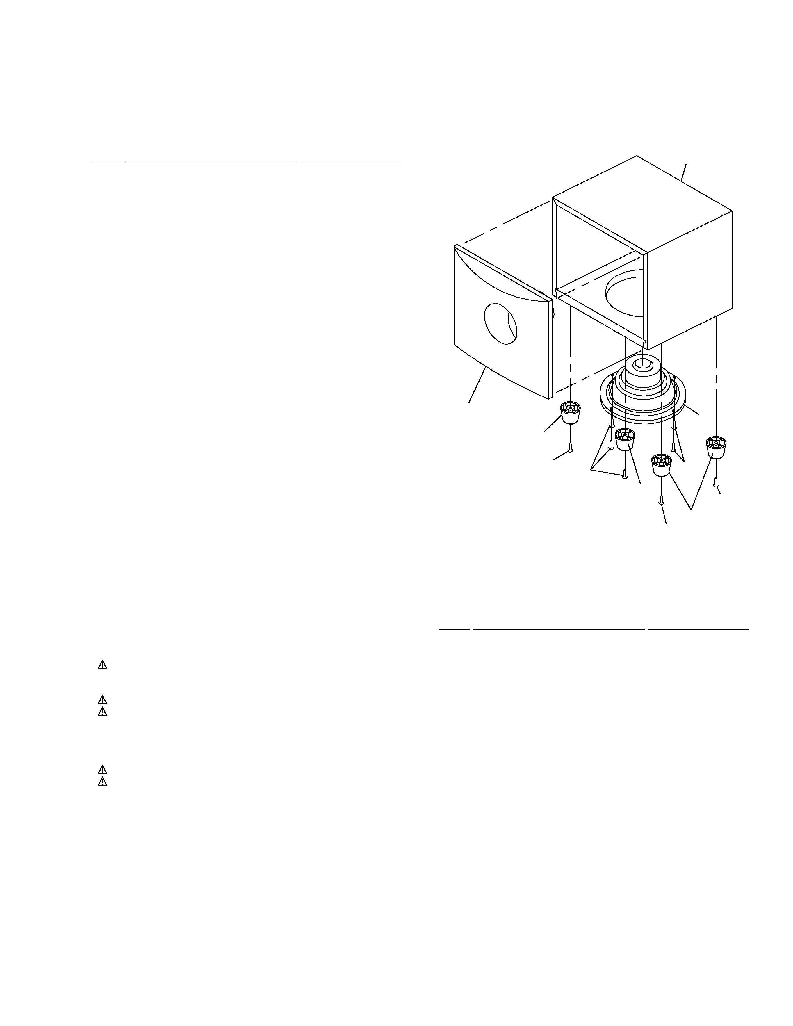
2.3 SUBWOOFER BOX&LABEL
Woofer Speaker Panel
SPK. Box
1
Screw
Screw
Screw
Screw
Screw
Plastic Foot
Plastic Foot
Plastic Foot
· SUBWOOFER BOX&LABEL PARTS LIST
Mark No.
Description
Part No.
1
170MM SPK. 6/6 OHM
02917006412S