
1
HTP305-SW
PIONEER CORPORATION
4-1, Meguro 1-Chome, Meguro-ku, Tokyo 153-8655, Japan
PIONEER ELECTRONICS SERVICE, INC.
P.O.Box 1760, Long Beach, CA 90801-1760, U.S.A.
© PIONEER CORPORATION 1999
CONTENTS
1. SAFETY INFORMATION .............................................. 2
2. DISASSEMBLY .............................................................. 3
3. PACKING, EXPLODED VIEWS AND PARTS LIST ....... 3
4. SCHEMATIC AND PCB CONNECTION DIAGRAMS .... 6
5. PCB PARTS LIST .......................................................... 8
6. PANEL FACILITIES ........................................................ 9
7. SPECIFICATIONS ....................................................... 10
Service
Manual
ORDER NO.
PET99020
POWERED SUBWOOFER
HTP305-SW KUCXC
2
HTP305-SW
1. SAFETY INFORMATION
This service manual is intended for qualified service technicians; it is not meant for the casual do-it-
yourselfer. Qualified technicians have the necessary test equipment and tools, and have been trained to
properly and safely repair complex products such as those covered by this manual.
Improperly preformed repairs can adversely affect the safety and reliability of the product and may void
the warranty. If you are not a qualified to perform the repair of this product properly and safely, you
should not risk trying to do so and refer the repair to a qualified service technician.
WARNING
Lead in solder used in this product is listed by the California Health and Welfare agency as a known reproductive
toxicant which may cause birth defects or other reproductive harm (California Health & Safety Code, Section
25249.5). When servicing or handling circuit boards and other components which contain lead in solder, avoid
unprotected skin contact with the solder. Also, when soldering do not inhale any smoke or fumes produced.
NOTICE
(FOR CANADIAN MODEL ONLY)
Fuse symbols
(fast operating fuse) and/or
(slow operating fuse) on PCB indicate that replacement
parts must be of identical designation.
REMARQUE
(POUR MODÈLE CANADIEN SEULEMENT)
Les symboles de fusible
(fusible de type rapide) et/ou
(fusible de type lent) sur CCI indiquent que
les pièces de remplacement doivent avoir la même désignation.
(FOR USA MODEL ONLY)
1.
SAFETY PRECAUTIONS
The following check should be performed for the
continued protection of the customer and service
technician.
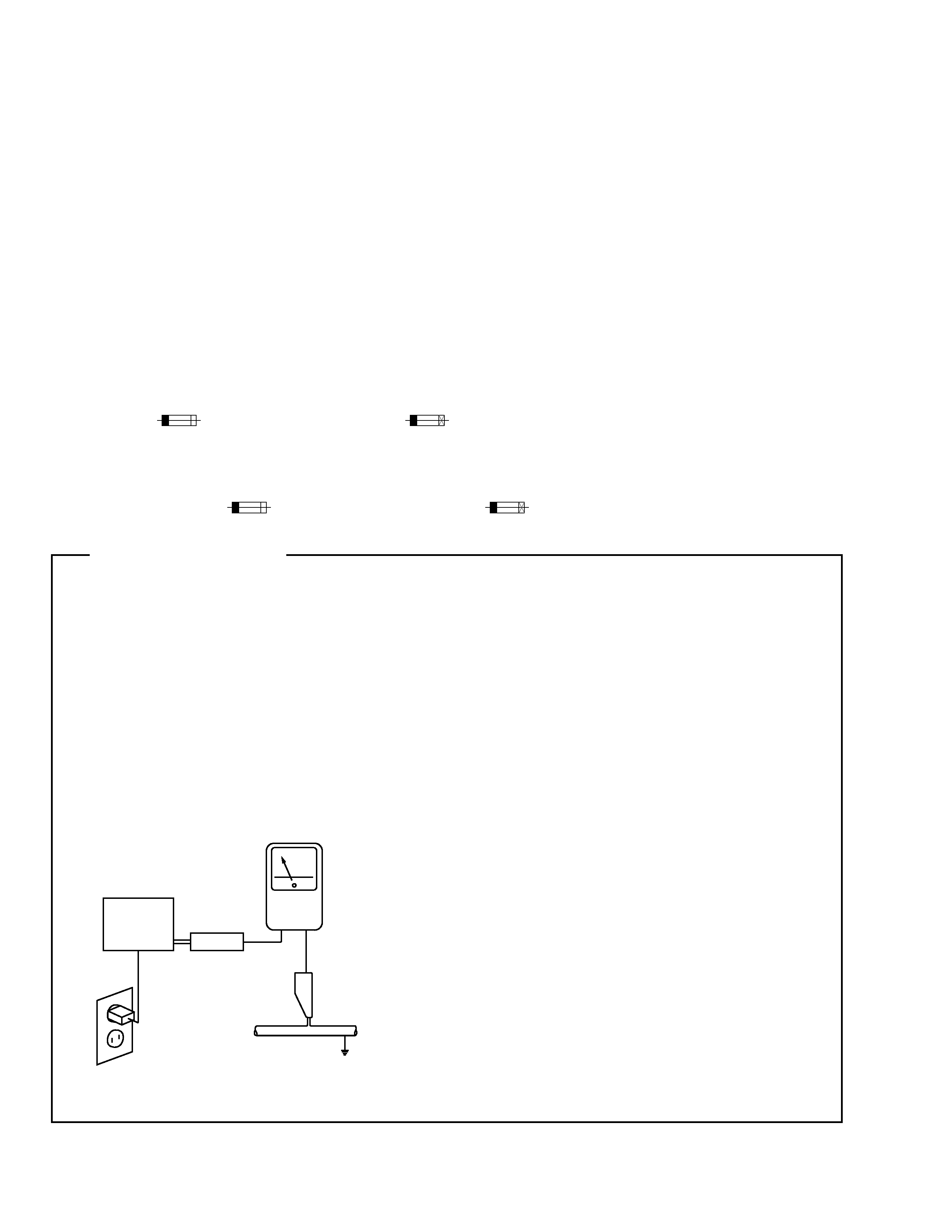
LEAKAGE CURRENT CHECK
Measure leakage current to a know earth ground
(water pipe, conduit, etc.) by connecting a leakage
current tester such as Simpson Model 229-2 or
equivalent between the earth ground and all exposed
metal parts of the appliance (input/output terminals,
screwheads, metal overlays, control shaft, etc.). Plug
the AC line cord of the appliance directly into a 120V
AC 60Hz outlet and turn the AC power switch on. Any
current measured must no exceed 0.5mA.
ANY MEASUREMENT NOT WITHIN THE LIMITS
OUTLINED ABOVE ARE INDICATIVE OF A
POTENTIAL SHOCK HAZARD AND MUST BE
CORRECTED BEFORE RERTURNING THE
APPLIANCE TO THE CUSTOMER.
2.
PRODUCT SAFETY NOTICE
Many electrical and mechanical parts in the appliance
have special safety related characteristic. These are
often not evident from visual inspection nor the
protection afforded by them necessarily can be
obtained by using replacement components rated for
voltage, wattage, etc. Replacement parts which have
these special safety characteristics are identified in
this Service Manual.
Electrical components having such features are
identified by marking with a D on the schematics and
on the parts list in this Service Manual.
The use of a substitute replacement component which
dose not have the same safety characteristics as the
PIONEER recommended replacement one, shown in
the parts list in this Service Manual, may create sock,
fire, or other hazards.
Product Safety is continuously under review and new
instructions are issued from time to time. For the latest
information, always consult the current PIONEER
Service Manual. A subscription to, or additional copies
of, PIONEER Service Manual may be obtained at a
nominal charge from PIONEER.
+
-
Reading should
not be above
0.5mA
Leakage
current
tester
Device
under
test
Test all
exposed metal
surfaces
Earth
ground
Also test with
plug reversed
(Using AC adapter
plug as required)
AC Leakage Test

3
HTP305-SW
2. DISASSEMBLY
q
POWER AMP SECTION
· Remove the 12 screws from the power amplifier.
· Remove the polyswitch assembly.
· Remove the connector lead, etc.
3. PACKING, EXPLODED VIEWS AND PARTS LIST
NOTES:
q
Parts marked by "NSP" are generally unavailable because they are not in our Master Spare Parts List.
q
The
mark found on some component parts indicates the importance of the safety factor of the part. Therefore, when replacing, be sure to use
parts of identical designation.
q
Parts marked by "
" are not always kept in stock. Their delivery time may be longer than usual or they may be unavailable.
q
GRILLE SECTION
· The grill is attached to the cabinet by its bosses applied
with adhesive. To detach it, pry it open by inserting a flate
blad screwdriver between the cabinet and the grille.
q
SPEAKER
· Remove each of the 4 screws.
3.1 PACKING
Parts List
Operating Instructions
268206
RCA Cable Accessory Pack
255245
Corner Pad Assy
264333
Poly Bag
266953
Packing Case
267218
Mark Description
Parts No.
4
HTP305-SW
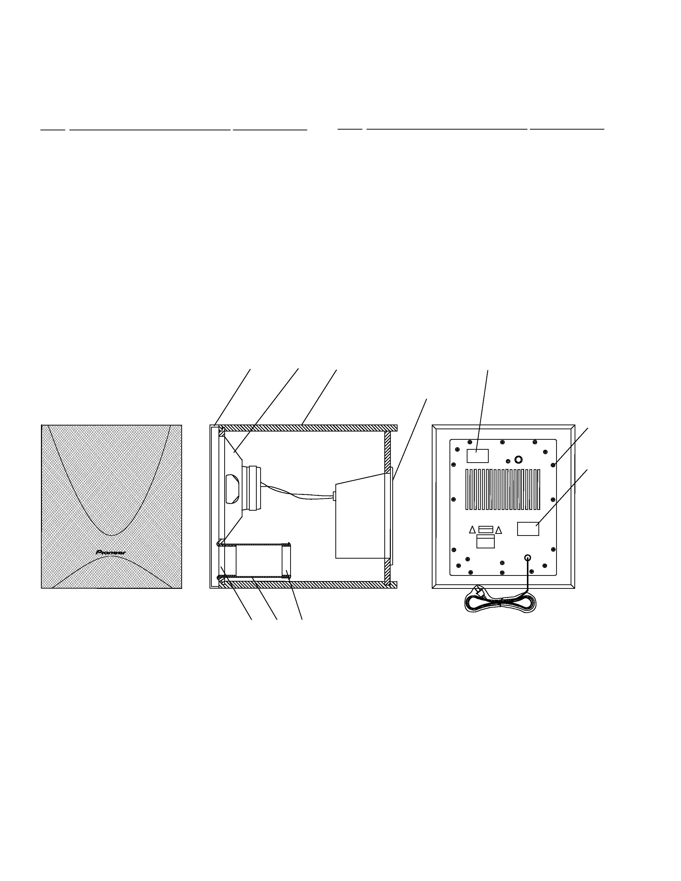
3.2 EXTERIOR SECTION
Parts List
Mark No.
Description
Parts No.
Mark No.
Description
Parts No.
Fig. 1
HTP305-SW
1
2
3
4
56
9
8
7
10
NSP
1
Cabinet Enclosure
264506
NSP
2
Amplifier Assembly
264571
3
Grille Assembly
264353
NSP
4
Paper Port Tube
256946
NSP
5
Front Port Ring
254306
NSP
6
Rear Port Ring
254346
NSP
7
Label FTC Sticker
268286
NSP
8
UL-CUL Label
268197
9
Transducer
264724
10
Screw (for Amplifier and Trans)
221904
5
HTP305-SW
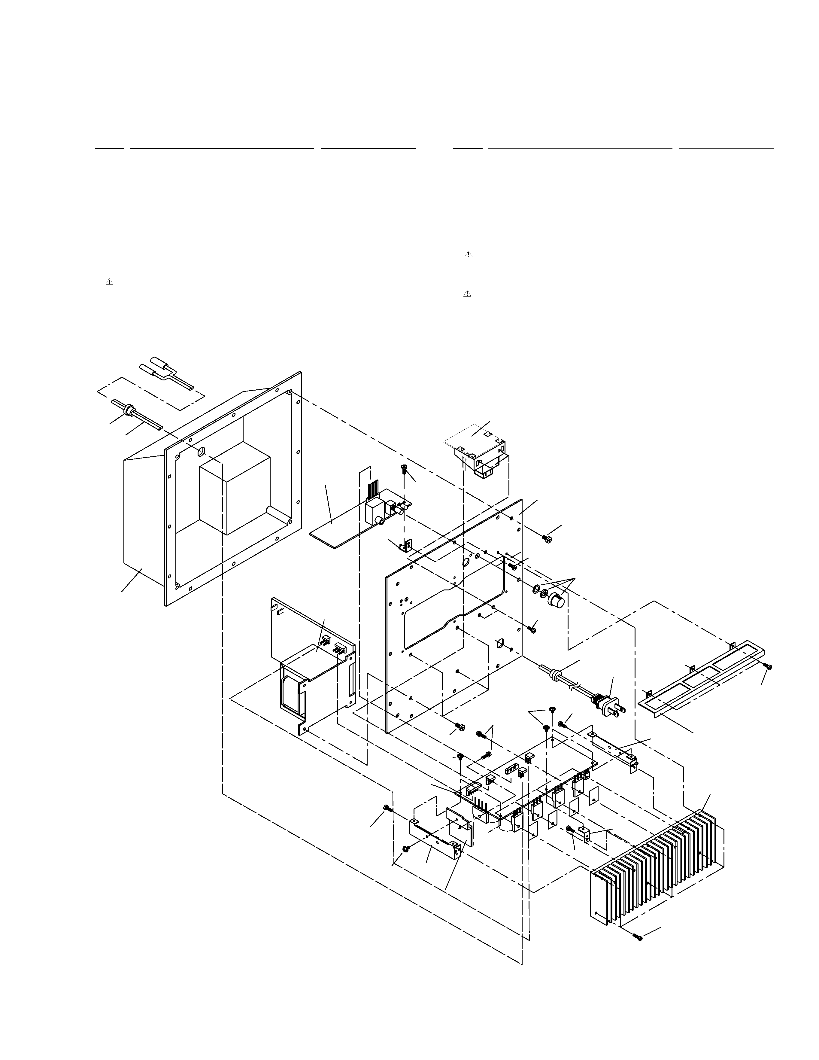
3.3 POWER AMP SECTION
Parts List
Mark No.
Description
Parts No.
20
22, 25
18
18
19
18
22, 25
4
22
5
14
6
18
1(2/2)
10
8
18
3, 12
19
17
21
16
7
9
18
15
23
18
24
1(1/2)
6
22, 25
Mark No.
Description
Parts No.
NSP
1
Main+Cont. Assy
047379
2
Nylon Binder
080558
3
BRKT Cover Heatsink
085424
4
BRKT PCB A
077860
5
BRKT PCB D
077878
6
BRKT PCB C
077876
7
Cushion Gasket
078786
8
Cushion Stopper
078519
9
2P Cord
077365
10
AC Cord
046947
11
Wire-Kit
047424
12
Cushion 3x200
078829
13
BRKT Trans Backup
046984
14
Heatsink Main
064592
15
Knob VR
072992
16
Mold Case
080267
17
Panel Rear Assy
047003
18
Screw (M3X10 BL)
075640
19
Screw (M4X10 BL)
075659
20
Screw (M3x12 BL)
075461
21
Trans Power
074919
22
Screw (3x6 ZC)
075153
23
Heatsink Diode
064596
24
Trans Backup
047073
25
Washer (3.2x6.5xt0.5)
075818