1
RECEIVER
+
+
+
+
+
BASS
OFF
SOUND
TONE
MPX
AUTO
ROOM
SETUP
TEST
TONE
SYSTEM
SETUP
CH LEVEL
TUNING
STATION
FM/AM TAPE/VCR
TV
CLASS
DIGITAL
INPUT SELECTOR
STB
DVD/DVR
TUNER
EDIT
SLEEP
STATUS
DIMMER
STANDBY/ON
MUTE
SURROUND
ENTER
VOLUME
STEREO
TREBLE
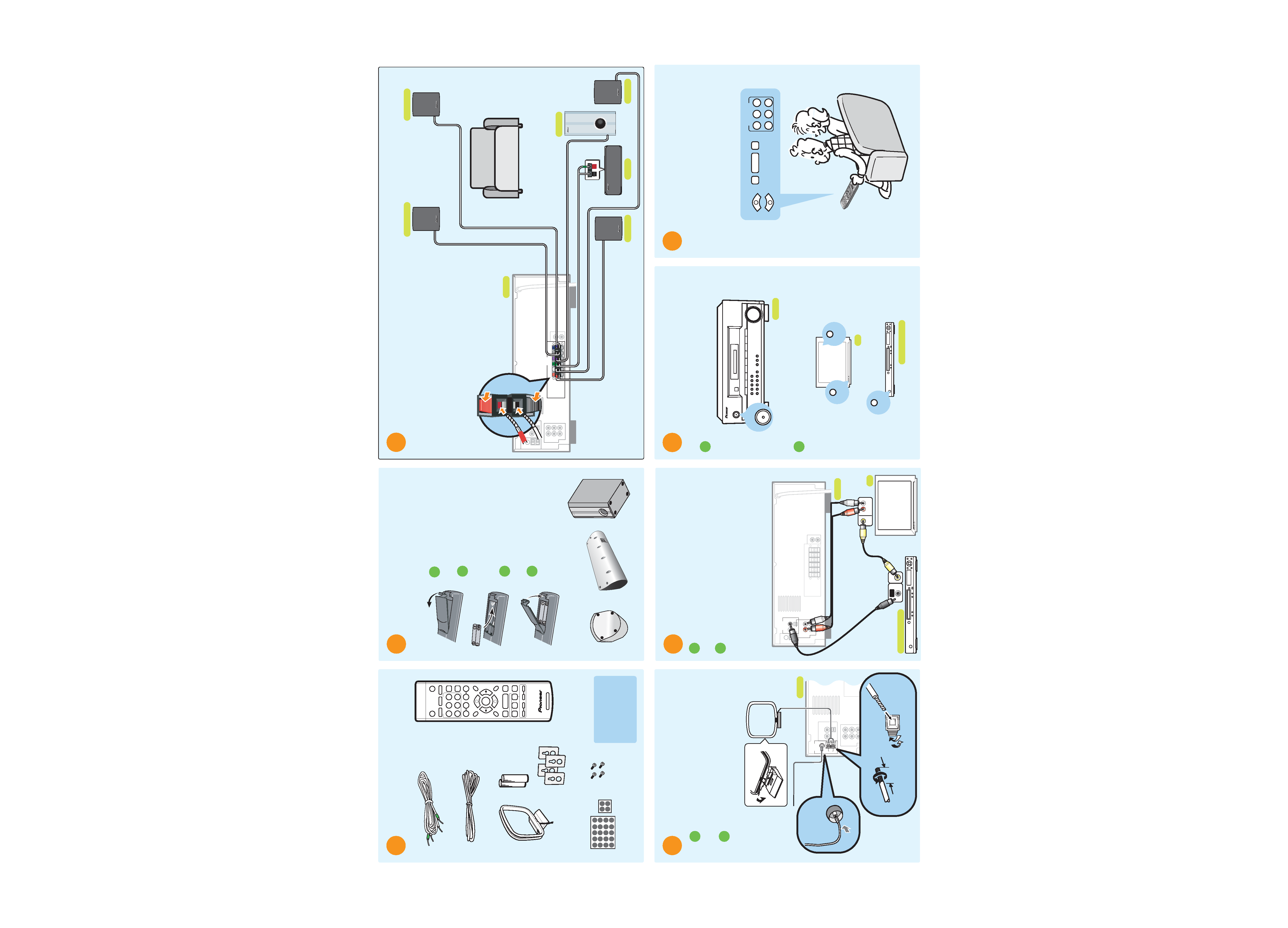
Check that you have all the
accessories.
Speaker cord (x1)
FM wire antenna
You should also have:
· Speakers (x5)
· Subwoofer
· Operating instructions
· Warranty card
AM loop
antenna
Non-skid pads
(1x20, 1x4)
Batteries (x2)
Remote control
Brackets (x4)
Screws (x4)
2
Front and surround speakers
Center speaker
Subwoofer
Put the batteries in the remote
control and stick the non-skid pads
to the base of the speakers.
1 Open the battery compartment on
the rear of the remote control.
Insert the supplied batteries
following the markings inside the
battery compartment to align
them correctly.
Replace the battery compartment
cover.
Stick the self-adhesive non-skid
pads to the underside of each
speaker, and to the underside of
the subwoofer. Use four pads per
speaker (see below).
2
3
4
5
DIGITAL
OUT
+
+
DIGITAL INPUT
(COAXIAL)
DVD/DVR
OUT
RL
IN
TV IN
AUDIO
AUDIO
OUT
VIDEO
IN
VIDEO
OUT
R
L
Connect the receiver to your DVD
player/ recorder.
1
Use a coaxial digital cord (not supplied) to connect the digital
output of your DVD player/ recorder to the DIGITAL INPUT
(COAXIAL) DVD/DVR jack.
2
Use a red/white stereo audio cord (not supplied) to connect the
AUDIO TV IN jack on the receiver to the audio output on your
TV.* This will allow you to listen to your TV through this
speaker system.
* Note that you must also connect the DVD player/ recorder's
video output to your TV's video input to watch a DVD video
(video cable is not supplied).
DVD player/ recorder
Receiver
TV
ANTENNA
FM
UNBAL
75
AM
LOOP
AM loop
antenna
FM wire antenna
3/8 in.
(10mm)
4 Connect antennas
1
Connect the FM wire antenna and fully extend along a
window frame or another suitable place that gives good
reception.
2
To connect the AM loop antenna, twist the exposed wire
strands together and insert into the terminal, then snap
the connector shut as shown below.
Receiver
6
VIDEO 1
STANDBY/ON
STANDBY/ON
STANDBY/ON
STANDBY/ON
VIDEO SELECT
Plug the receiver, DVD player/
recorder and TV into a convenient
AC outlet.
1 Press STANDBY/ON to switch on the receiver.
2
Switch on your DVD player/ recorder and TV, and set the TV to
the correct video input.
DVD player/ recorder
Receiver
TV
7
+
VOLUME
AUTO
SURROUND
STEREO
FM/AM TAPE/VCR
TV
DIGITAL
INPUT SELECTOR
STB
DVD/DVR
After switching on, make any
necessary settings required by the
DVD player/ recorder, then you're
ready to start enjoying your home
theater system.
Refer to the receiver's operating instructions for a detailed
explanation of this system's surround sound features.
3
For the best surround sound, set up your
speakers like this. The front left and right
speakers should be about 69 feet apart.
Connect each speaker to the receiver using the
supplied speaker wires.
To connect, insert the colored wire into the matching colored (
+) tab
and the other wire into the black (
) tab as shown below. Connect the
center speaker the same way (matching the wire the color-coded label).
Note that the color-coded tabs are as follows:
·
Red : Front right speaker
·
Purple : Subwoofer
·
White : Front left speaker
·
Grey : Surround right speaker
·
Green : Center speaker
·
Blue : Surround left speaker
Listening position
SPEAKERS
+
+
RL
R
L
CENTER
SUB
WOOFER
FRONT
SURROUND
Front left
Front right
Surround left
Surround right
Center
Subwoofer
Receiver
HTP-2500/2600 Quick Start Guide
For detailed instructions, see the Operating Instructions supplied and / or contact one of our knowledgeable Pioneer Customer Service Representatives at 1 - (800) 421-1404.
HTP2500.p65
05.1.17, 4:59 PM
1

Setting Up Your HTP-2500/2600 Home Theater System At-a-Glance
For detailed instructions, see the Operating Instructions supplied and / or contact one of our knowledgeable Pioneer Customer Service Representatives at 1 - (800) 421-1404.
AUDIO
DIGITAL INPUT
(COAXIAL)
DVD/DVR
TV IN
SPEAKERS
+
+
RL
R
L
CENTER
SUB
WOOFER
FRONT
SURROUND
DVD player/ recorder
Front L.
Surround L.
Surround R.
Front R.
Center
Subwoofer
COAXIAL OUT
VIDEO OUT
Receiver
+
AUDIO
OUT
VIDEO
IN
Refer to the following diagram when making system connections for a full surround sound
setup. Note that the TV, DVD player/ recorder and some accessories are not included. Refer
to the reverse side of this sheet to check what's supplied with the HTP-2500/2600.
Not supplied
Not supplied
Not supplied
<ARE7375-A>
5 7 mm
Mounting screw
(not supplied)
Bracket screw
(supplied)
5 mm
10 mm
Wall-mounting the front and surround speaker system
Attaching the brackets
÷ Make sure to tighten the supplied screw as securely as possible when attaching
the bracket to the back of the speaker.
÷ Please do not attach the brackets to the center speaker.
Before mounting
÷ Remember that the speaker system is heavy and that its weight could cause the
wood screws to work loose, or the wall material to fail to support it, resulting in the
speaker falling. Make sure that the wall on which you intend to mount the speakers
is strong enough to support them. Do not mount on plywood or soft surface walls.
÷ Mounting screws are not supplied. Use screws that are suitable for the wall
material and that will support the weight of the speaker.
÷ If you are unsure of the material and strength of the walls, consult a professional for advice.
÷ Pioneer is not responsible for any accidents or damage that result from improper installation.
HTP2500.p65
05.1.17, 5:00 PM
2