ORDER NO.
PIONEER CORPORATION 4-1, Meguro 1-chome, Meguro-ku, Tokyo 153-8654, Japan
PIONEER ELECTRONICS SERVICE, INC. P.O. Box 1760, Long Beach, CA 90801-1760, U.S.A.
PIONEER EUROPE N.V. Haven 1087, Keetberglaan 1, 9120 Melsele, Belgium
PIONEER ELECTRONICS ASIACENTRE PTE. LTD. 253 Alexandra Road, #04-01, Singapore 159936
PIONEER CORPORATION 1999
RRV2259
T ZZK DEC. 1999 Printed in Japan
THIS MANUAL IS APPLICABLE TO THE FOLLOWING MODEL(S) AND TYPE(S).
Type
Model
Power Requirement
Remarks
GRM-01
ZBXJ
DC power supply
DIGITAL PRESET SAMPLER
GRM-01
1. SAFETY INFORMATION ...................................... 2
2. EXPLODED VIEWS AND PARTS LIST ................ 3
3. SCHEMATIC DIAGRAM ....................................... 4
4. PCB CONNECTION DIAGRAM ............................ 6
5. PCB PARTS LIST ................................................. 8
CONTENTS
GRM-01
2
1. SAFETY INFORMATION
This service manual is intended for qualified service technicians; it is not meant for the casual
do-it-yourselfer. Qualified technicians have the necessary test equipment and tools, and have been
trained to properly and safely repair complex products such as those covered by this manual.
Improperly performed repairs can adversely affect the safety and reliability of the product and may
void the warranty. If you are not qualified to perform the repair of this product properly and safely, you
should not risk trying to do so and refer the repair to a qualified service technician.
WARNING
This product contains lead in solder and certain electrical parts contain chemicals which are known to the state of California to
cause cancer, bir th defects or other reproductive harm.
Health & Safety Cod e Section 25249.6 Proposition 65
NOTICE
(FOR CANADIAN MODEL ONLY)
Fuse symbols
(fast operating fuse)
and/or
(slow operating fuse) on PCB indicate that replacement
parts must be of identical designation.
REMARQUE
(POUR MODÈLE CANADIEN SEULEMENT)
Les symboles de fusible
(fusible de type rapide)
et/ou
(fusible de type lent) sur CCI indiquent que
les pièces de remplacement doivent avoir la même désignation.
ANY MEASUREMENTS NOT WITHIN THE
LIMITS OUTLINED ABOVE ARE INDICATIVE
OF A POTENTIAL SHOCK HAZARD AND
MUST BE CORRECTED BEFORE RETURN-
ING THE APPLIANCE TO THE CUSTOMER.
2. PRODUCT SAFETY NOTICE
Many electrical and mechanical parts in the appliance
have special safety related characteristics. These are
often not evident
from visual
inspection nor the
protection afforded by them necessarily can be obtained
by using replacement components rated for voltage,
wattage, etc. Replacement parts which have these
special safety characteristics are identified in this
Service Manual.
Electrical components having such features are
identified by marking with a
on the schematics and
on the parts list in this Service Manual.
The use of a substitute replacement component which
does not have the same safety characteristics as the
PIONEER recommended replacement one, shown in the
parts list in this Service Manual, may create shock, fire,
or other hazards.
Product Safety is continuously under review and new
instructions are issued from time to time. For the latest
information, always consult the current PIONEER
Service Manual. A subscription to, or
additional copies
of, PIONEER Service Manual may be obtained at a
nominal charge from PIONEER.
(FOR USA MODEL ONLY)
1. SAFETY PRECAUTIONS
The following check should be performed for the
continued protection of the customer and service
technician.
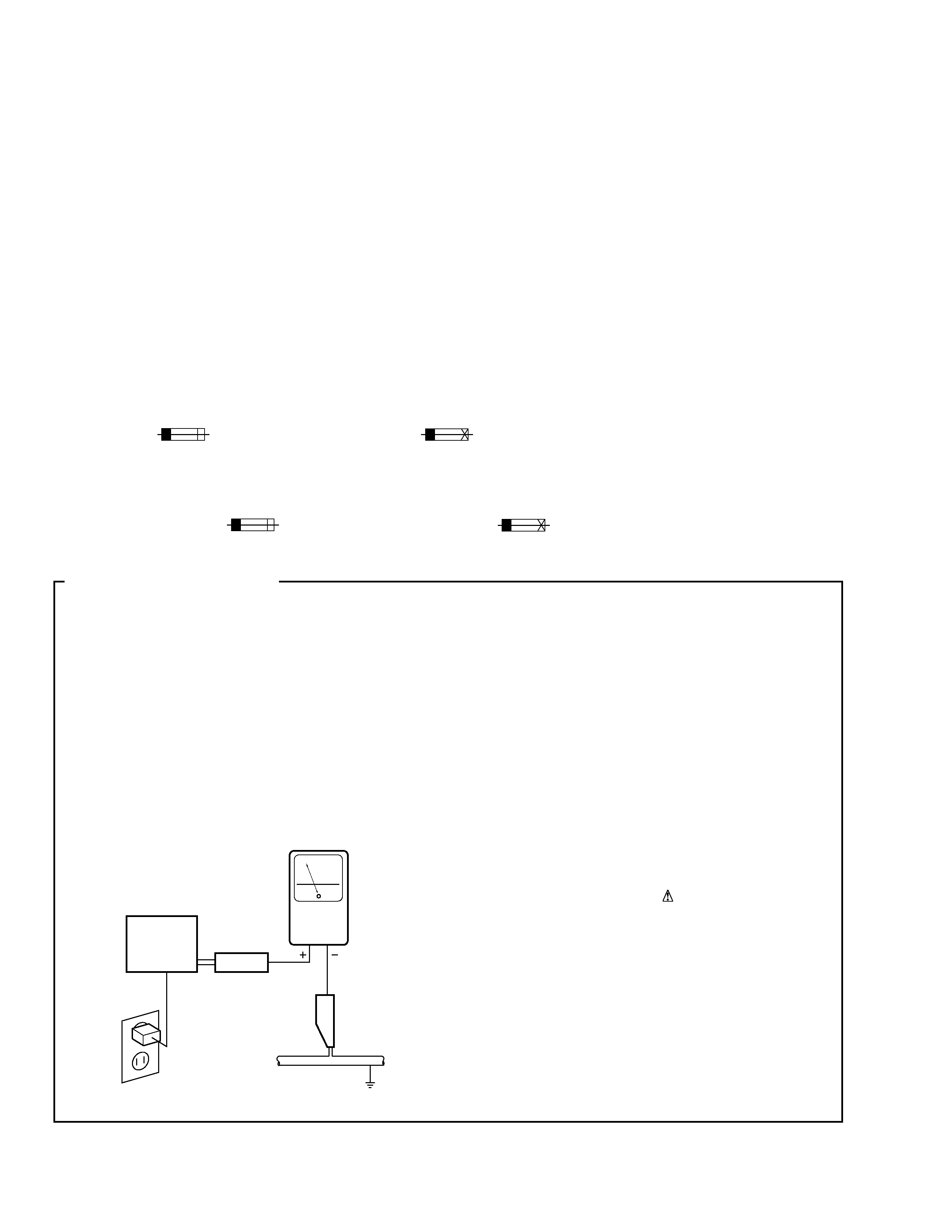
LEAKAGE CURRENT CHECK
Measure leakage current to a known earth ground
(water pipe, conduit, etc.) by connecting a leakage
current tester such as Simpson Model 229-2 or
equivalent between the earth ground and all exposed
metal parts of the appliance (input/output terminals,
screwheads, metal overlays, control shaft, etc.). Plug
the AC line cord of the appliance directly into a 120V
AC 60 Hz outlet and turn the AC power switch on. Any
current measured must not exceed 0.5 mA.
Device
under
test
Leakage
current
tester
Earth
ground
Reading should
not be above
0.5 mA
Also test with
plug reversed
(Using AC adapter
plug as required)
Test all
exposed metal
surfaces
AC Leakage Test
GRM-01
3
1
2
7
3
8
5
10
10
10
10
4
6
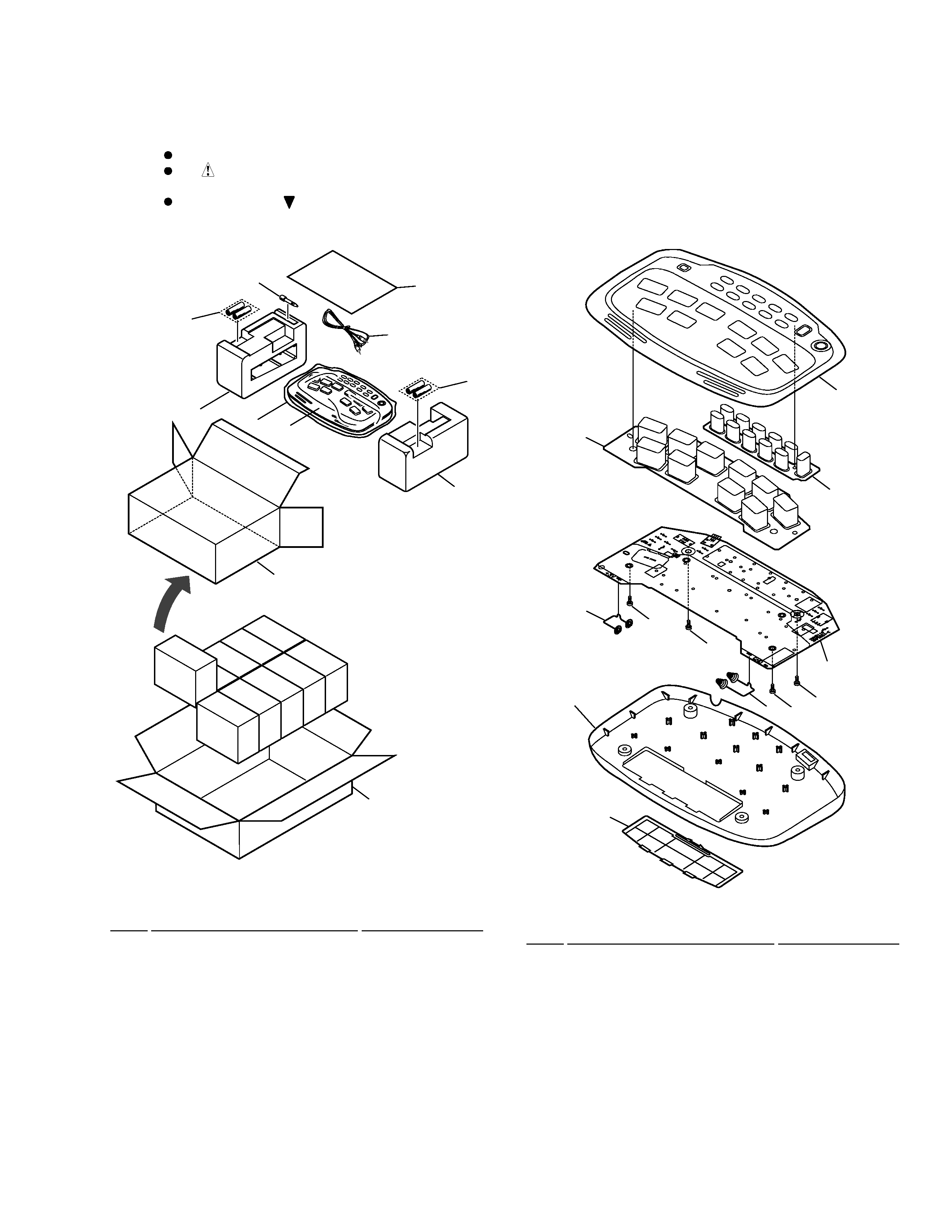
1
MUSIC PAD ASSY
XWM3119
2
Battery Spring A
XBH3004
3
Battery Spring B
XBH3005
4
Rubber Button A
XAD3036
5
Rubber Button B
XAD3037
6
Top Cover
XAK3115
7
Bottom Case
XAK3116
8
Battery Caver
XMR3011
9
· · · · · ·
10
Screw
BPZ30P100FZK
Mark No.
Description
Part No.
÷ MUSIC PAD PARTS LIST
2.2 MUSIC PAD
2. EXPLODED VIEWS AND PARTS LIST
Parts marked by "NSP" are generally unavailable because they are not in our Master Spare Parts List.
The
mark found on some component parts indicates the importance of the safety factor of the part.
Therefore, when replacing, be sure to use parts of identical designation.
Screws adjacent to
mark on product are used for disassembly.
NOTES:
2.1 PACKING
÷ PACKING PARTS LIST
1
Music Pad
XXD3021
NSP
2
Dry Cell Battery (R6P, AA)
VEM-013
3
Cord With Plug
XDE3025
4
Convert Plug
XKM3003
5
Operating Instructions
XRE3029
(English/Arabian/Russian/
Chinese/Spanish/French)
6
Pad L
XHA3022
7
Pad R
XHA3023
8
Packing Case
XHD3116
9
Packing Case
XHD3115
10
Packing Sheet
XHG3007
Mark No.
Description
Part No.
7
8
9
6
10
1
2
4
5
3
2
GRM-01
4
A
B
C
D
1
23
4
12
3
4
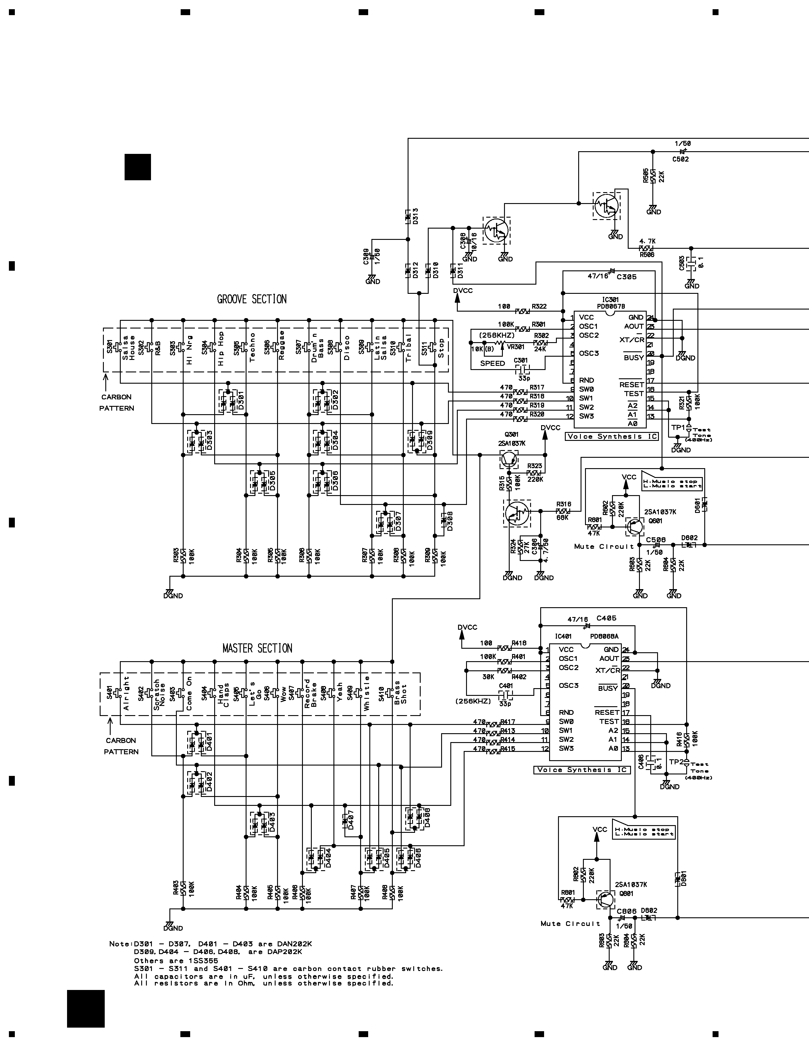
MUSIC PAD ASSY
(XWM3119)
Q302
DTC114TK
Q501
DTC114TK
Q303
DTC144TK
A
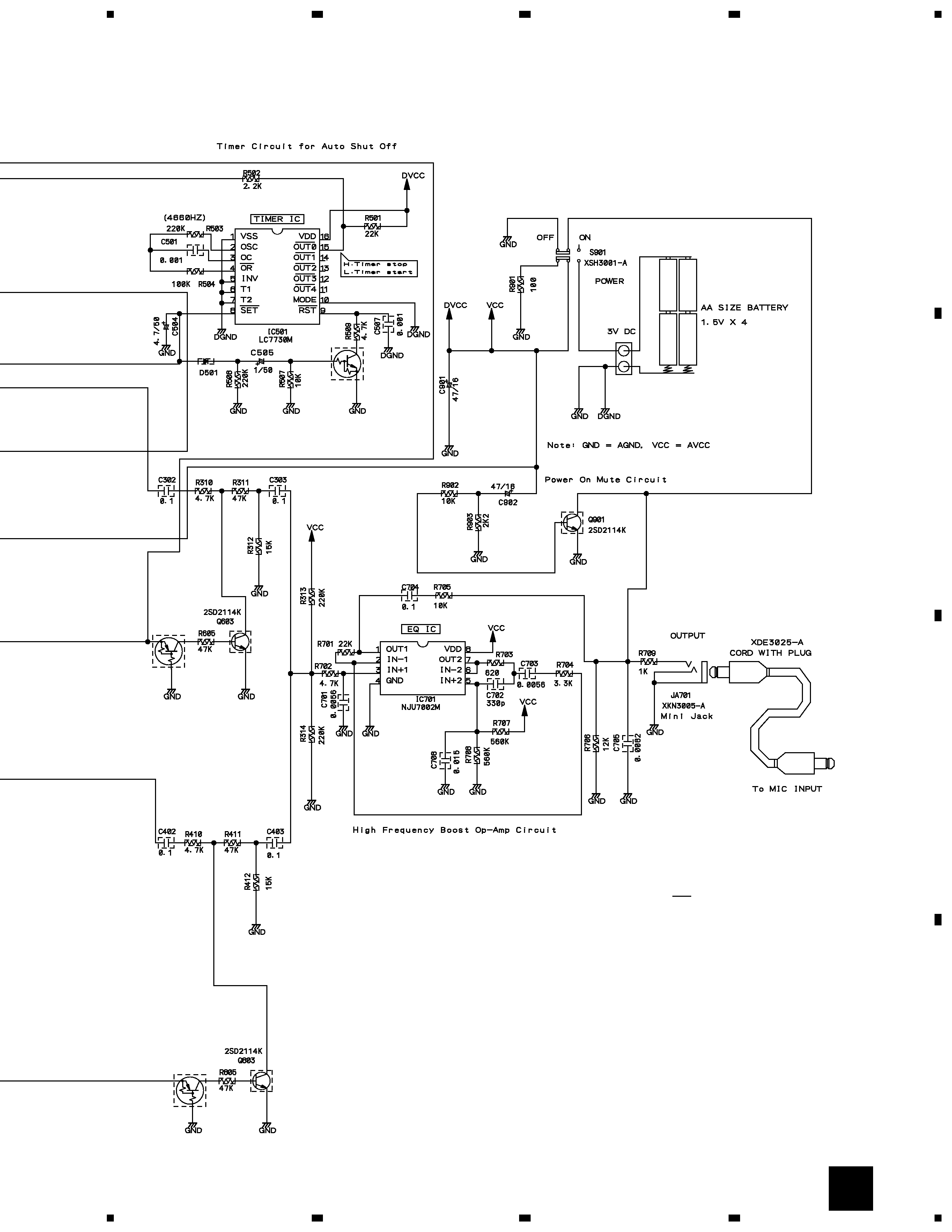
3. SCHEMATIC DIAGRAM
3.1 MUSIC PAD ASSY
A
GRM-01
5
A
B
C
D
5
67
8
5
6
7
8
Q802
DTA114TK
Q602
DTA114TK
Q502
DTC114TK
S301 : SALSA HOUSE
S302 : R&B
S303 : HI NRG
S304 : HIP HOP
S305 : TECHNO
S306 : REGGAE
S307 : DRUM'N BASS
S308 : DISCO
S309 : LATIN SALSA
S310 : TRIBAL
S311 : STOP
S401 : ALRIGHT
S402 : SCRATCH NOISE
S403 : COME ON
S404 : HAND CLAPS
S405 : LET'S GO
S406 : WOW
S407 : RECORD BRAKE
S408 : YEAH
S409 : WHISTLE
S410 : BRASS SHOT
S901 : POWER ON/OFF
Note : When ordering service parts, be sure to refer to "EXPLODED VIEWS and PARTS LIST" or "PCB PARTS LIST"
A