ORDER NO.
PIONEER ELECTRONIC CORPORATION 4-1, Meguro 1-Chome, Meguro-ku, Tokyo 153-8654, Japan
PIONEER ELECTRONICS SERVICE, INC. P.O. Box 1760, Long Beach, CA 90801-1760, U.S.A.
PIONEER ELECTRONIC (EUROPE) N.V. Haven 1087, Keetberglaan 1, 9120 Melsele, Belgium
PIONEER ELECTRONICS ASIACENTRE PTE. LTD. 253 Alexandra Road, #04-01, Singapore 159936
PIONEER ELECTRONIC CORPORATION 1999
c
GR-209
RRV2147
1. SAFETY INFORMATION ...................................... 2
2. EXPLODED VIEWS AND PARTS LIST ................ 3
3. SCHEMATIC DIAGRAM ....................................... 6
4. PCB CONNECTION DIAGRAM ............................ 8
5. PCB PARTS LIST ............................................... 10
6. ADJUSTMENT .................................................... 10
7. GENERAL INFORMATION ................................ 11
7.1 IC .................................................................. 11
8. PANEL FACILITIES AND SPECIFICATIONS .... 13
CONTENTS
T ZZR MAY 1999 Printed in Japan
THIS MANUAL IS APPLICABLE TO THE FOLLOWING MODEL(S) AND TYPE(S).
GRAPHIC EQUALIZER
Type
Model
Power Requirement
Remarks
GR-209
MYXCN1
AC220 230V
SDXCN1
AC110/120127/220/240V
With the voltage selector
209
STANDBY/ON
2
GR-209
1. SAFETY INFORMATION
This service manual is intended for qualified service technicians ; it is not meant for the casual do-it-
yourselfer. Qualified technicians have the necessary test equipment and tools, and have been trained
to properly and safely repair complex products such as those covered by this manual.
Improperly performed repairs can adversely affect the safety and reliability of the product and may
void the warranty. If you are not qualified to perform the repair of this product properly and safely, you
should not risk trying to do so and refer the repair to a qualified service technician.
WARNING
This product contains lead in solder and certain electrical parts contain chemicals which are known to the state of California to cause
cancer, birth defects or other reproductive harm.
Health & Safety Code Section 25249.6 Proposition 65
NOTICE
(FOR CANADIAN MODEL ONLY)
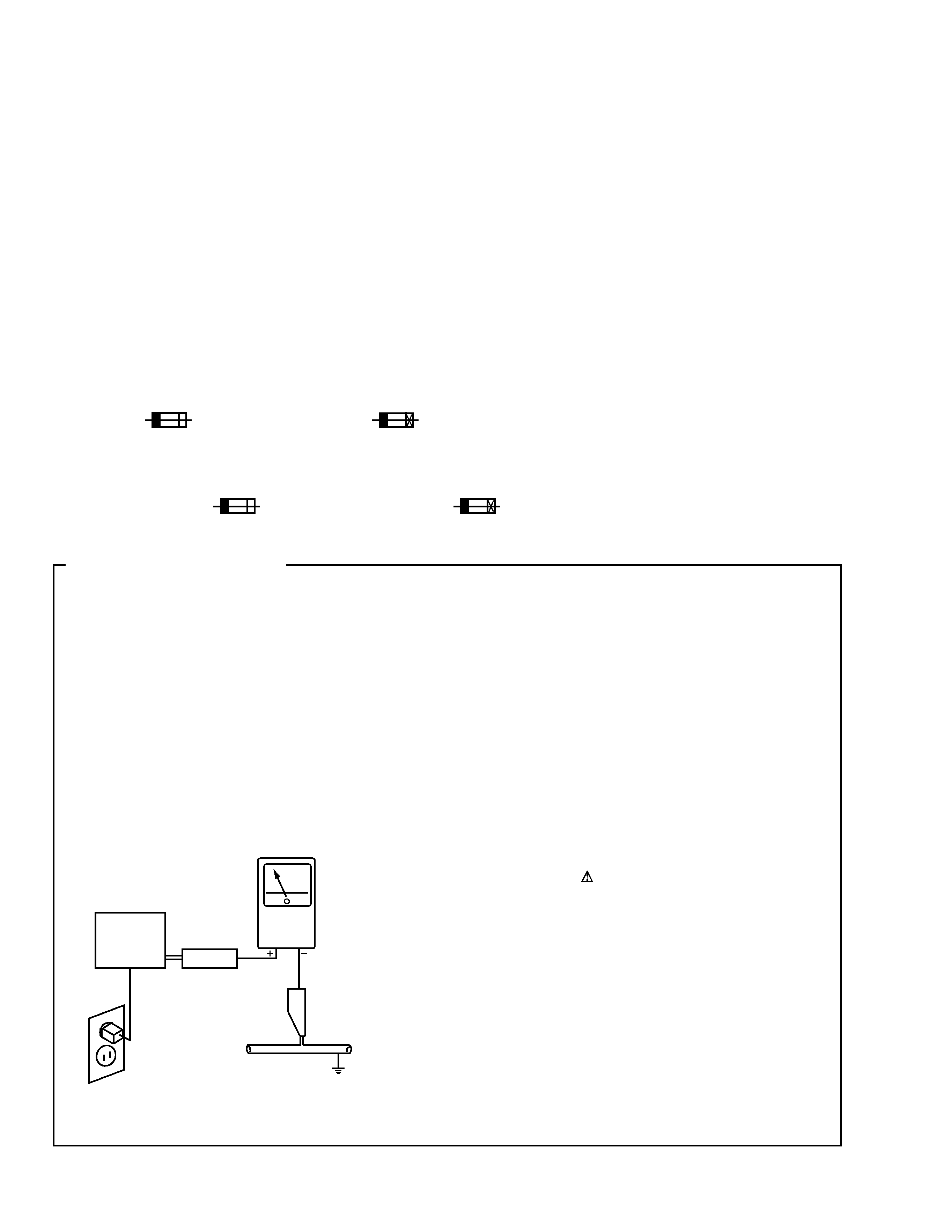
Fuse symbols
(fast operating fuse) and/or
(slow operating fuse) on PCB indicate that replacement parts must
be of identical designation.
REMARQUE
(POUR MODÈLE CANADIEN SEULEMENT)
Les symboles de fusible
(fusible de type rapide) et/ou
(fusible de type lent) sur CCI indiquent que les pièces
de remplacement doivent avoir la même désignation.
ANY MEASUREMENTS NOT WITHIN THE LIMITS
OUTLINED ABOVE ARE INDICATIVE OF A POTENTIAL
SHOCK HAZARD AND MUST BE CORRECTED BEFORE
RETURNING THE APPLIANCE TO THE CUSTOMER.
2. PRODUCT SAFETY NOTICE
Many electrical and mechanical parts in the appliance
have special safety related characteristics. These are
often not evident from visual inspection nor the protection
afforded by them necessarily can be obtained by using
replacement components rated for voltage, wattage, etc.
Replacement parts which have these special safety
characteristics are identified in this Service Manual.
Electrical components having such features are identified
by marking with a
on the schematics and on the parts list
in this Service Manual.
The use of a substitute replacement component which does
not have the same safety characteristics as the PIONEER
recommended replacement one, shown in the parts list in
this Service Manual, may create shock, fire, or other hazards.
Product Safety is continuously under review and new
instructions are issued from time to time. For the latest
information, always consult the current PIONEER Service
Manual. A subscription to, or additional copies of, PIONEER
Service Manual may be obtained at a nominal charge from
PIONEER.
1. SAFETY PRECAUTIONS
The following check should be performed for the
continued protection of the customer and service
technician.
LEAKAGE CURRENT CHECK
Measure leakage current to a known earth ground (water
pipe, conduit, etc.) by connecting a leakage current tester
such as Simpson Model 229-2 or equivalent between the
earth ground and all exposed metal parts of the appliance
(input/output terminals, screwheads, metal overlays, control
shaft, etc.). Plug the AC line cord of the appliance directly
into a 120V AC 60Hz outlet and turn the AC power switch
on. Any current measured must not exceed 0.5mA.
(FOR USA MODEL ONLY)
Leakage
current
tester
Reading should
not be above
0.5mA
Device
under
test
Test all
exposed metal
surfaces
Also test with
plug reversed
(Using AC adapter
plug as required)
Earth
ground
AC Leakage Test
3
GR-209
(English/French/German/Italian
/Dutch/Swedish/Spanish/Portuguese)
5
Operating Instructions
Not used
15202091-0297
(English/Spanish/Chinese)
6
Power Plag Adaptor
Not used
VKX1007
7
Carton Box
15302090-0297
15302091-0297
10
CAUTION 220V LABEL
Not used
ARR7003
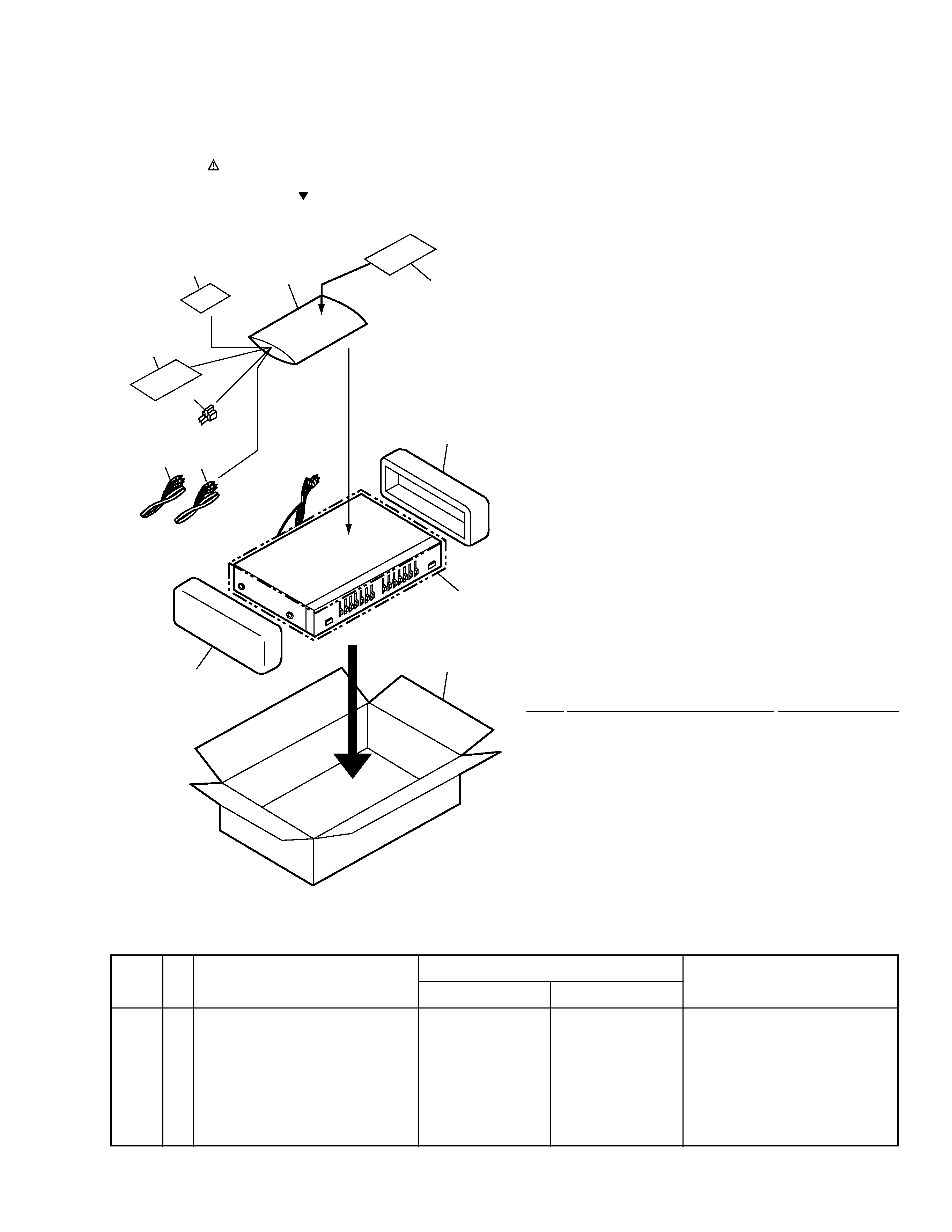
2.1 PACKING
(1)PACKING PARTS LIST
Mark No.
Description
Part No.
2. EXPLODED VIEWS AND PARTS LIST
NOTES:
· Parts marked by "NSP" are generally unavailable because they are not in our Master Spare Parts List.
· The mark found on some component parts indicates the importance of the safety factor of the part.
Therefore, when replacing, be sure to use parts of identical designation.
· Screws adjacent to mark on the product are used for disassembly.
4
8
6
3
2
5
1
1
7
9
10
1
Pin Plug Cords (L = 1m)
PDE1248
2
Polyform L
14904081-000
3
Polyform R
14904082-000
4
Polyethlene Bag
Z21-038
(0.03X230X340)
5
Operating Instructions
See Contrast table (2)
6
Power Plag Adaptor
See Contrast table (2)
7
Carton Box
See Contrast table (2)
NSP
8
Warranty Card
· · · · ·
NSP
9
Packing Sheet
· · · · ·
10
CAUTION 220V LABEL
See Contrast table (2)
Mark
MYXCN1 type
SDXCN1 type
(2) CONTRAST TEBLE
GR-209/MYXCN1 and SDXCN1 are constructed the same except for the following:
5
Operating Instructions
15202090-0297
Not used
Part No.
Remarks
Symbol and Description
No.
4
GR-209
9
18
18
18
18
18
18
10 (1/4 : EQ PCB )
10 (3/4 : EQ ON/OFF PCB)
10
(2/4 : POWER PCB )
1
5
4
6
6
6
6
7
2
2
19
18
18
18
18
18
18
18
18
18
18
18
18
18
18
18
13
18
3
3
19
18
18
20
20
18
19
19
22
23
3
3
17
6
8
10(4/4 : JACK PCB)
6
6
6
13
13
13
18
18
15
16
21
SDXCN1 type Only
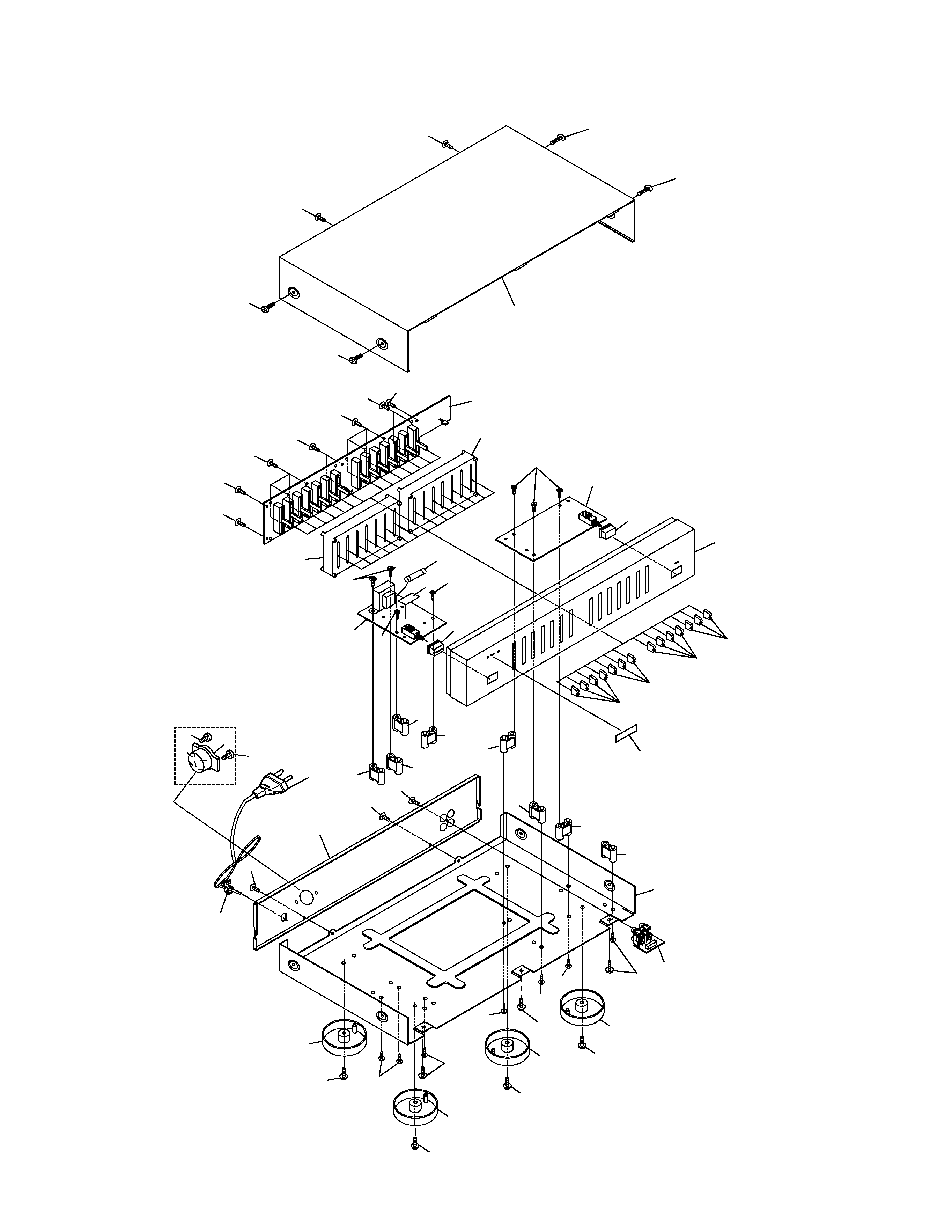
2.2 EXTERIOR SECTION
5
GR-209
(1) EXTERIOR SECTION PARTS LIST
Mark No.
Description
Part No.
1
Front Cabinet
10104080-002
2
EQ Bracket
12904082-010
3
EQ Knob(Black)
12704082-010
4
Power Button
12804080-010
5
EQ On/Off Button
12804080-110
6
Post
13004082-000
7
Rear Panel
See Contrast table (2)
NSP
8
Bottom Cabinet
· · · · ·
9
Bonnet Cover
18004083-010
10
Main Bord Assy
See Contrast table (2)
11
· · · · ·
12
· · · · ·
13
Foot(Black)W/O H/S
13821007-010
14
· · · · ·
15
AC Power Cord
02360020-004
NSP
16
Bushing
13000000-001
17
Name Plate
PAM1776
18
Screw
BBZ30P080FZK
19
Screw
IBZ30P080FMC
20
Screw
BPZ26P080FMC
21
Voltage Selector
See Contrast table (2)
22
Fuse (630mA/250V)
05005020-063
23
Fuse Caution Label
15454081-003
Mark
MYXCN1 type
SDXCN1 type
(2) CONTRAST TEBLE
GR-209/MYXCN1 and SDXCN1 are constructed the same except for the following:
7
Rear Panel
18004085-102
18004085-201
10
Main Bord Assy
GR209/MY
GR209/SD
21
Voltage Selector
Not used
AKX-507
Part No.
Remarks
Symbol and Description
No.