ORDER NO.
CRT2167
Service
Manual
BRIDGEABLE POWER AMPLIFIER
PIONEER ELECTRONIC CORPORATION
4-1, Meguro 1-Chome, Meguro-ku, Tokyo 153-8654, Japan
PIONEER ELECTRONICS SERVICE INC.
P.O.Box 1760, Long Beach, CA 90801-1760 U.S.A.
PIONEER ELECTRONIC [EUROPE] N.V.
Haven 1087 Keetberglaan 1, 9120 Melsele, Belgium
PIONEER ELECTRONICS ASIACENTRE, PTE.LTD. 501 Orchard Road, #10-00, Wheelock Place, Singapore 238880
C PIONEER ELECTRONIC CORPORATION 1998
K-ZEU. JAN. 1998 Printed in Japan
GM-X422
X1R/UC, ES, EW
CONTENTS
1. SAFETY INFORMATION ............................................1
2. EXPLODED VIEWS AND PARTS LIST .......................2
3. SCHEMATIC DIAGRAM .............................................6
4. PCB CONNECTION DIAGRAM ..................................8
5. ELECTRICAL PARTS LIST ........................................12
6. ADJUSTMENT..........................................................14
7. GENERAL INFORMATION .......................................15
7.1 DISASSEMBLY ...................................................15
8. OPERATIONS AND SPECIFICATIONS.....................16
1. SAFETY INFORMATION
This service manual is intended for qualified service technicians; it is not meant for the casual do-it-yourselfer.
Qualified technicians have the necessary test equipment and tools, and have been trained to properly and safely repair
complex products such as those covered by this manual.
Improperly performed repairs can adversely affect the safety and reliability of the product and may void the warranty.
If you are not qualified to perform the repair of this product properly and safely, you should mot risk trying to do so
and refer the repair to a qualified service technician.
UC model
CAUTION
This service manual is intended for qualified service technicians; it is not meant for the casual do-it-yourselfer.
Qualified technicians have the necessary test equipment and tools, and have been trained to properly and safely repair
complex products such as those covered by this manual.
Improperly performed repairs can adversely affect the safety and reliability of the product and may void the warranty.
If you are not qualified to perform the repair of this product properly and safely; you should not risk trying to do so
and refer the repair to a qualified service technician.
WARNING
Lead in solder used in this product is listed by the California Health and Welfare agency as a known reproductive toxi-
cant which may cause birth defects or other reproductive harm (California Health & Safety Code, Section 25249.5).
When servicing or handling circuit boards and other components which contain lead in solder, avoid unprotected skin
contact with the solder. Also, when soldering do not inhale any smoke or fumes produced.
GM-X322
X1R/UC
2
GM-X422, GM-X322
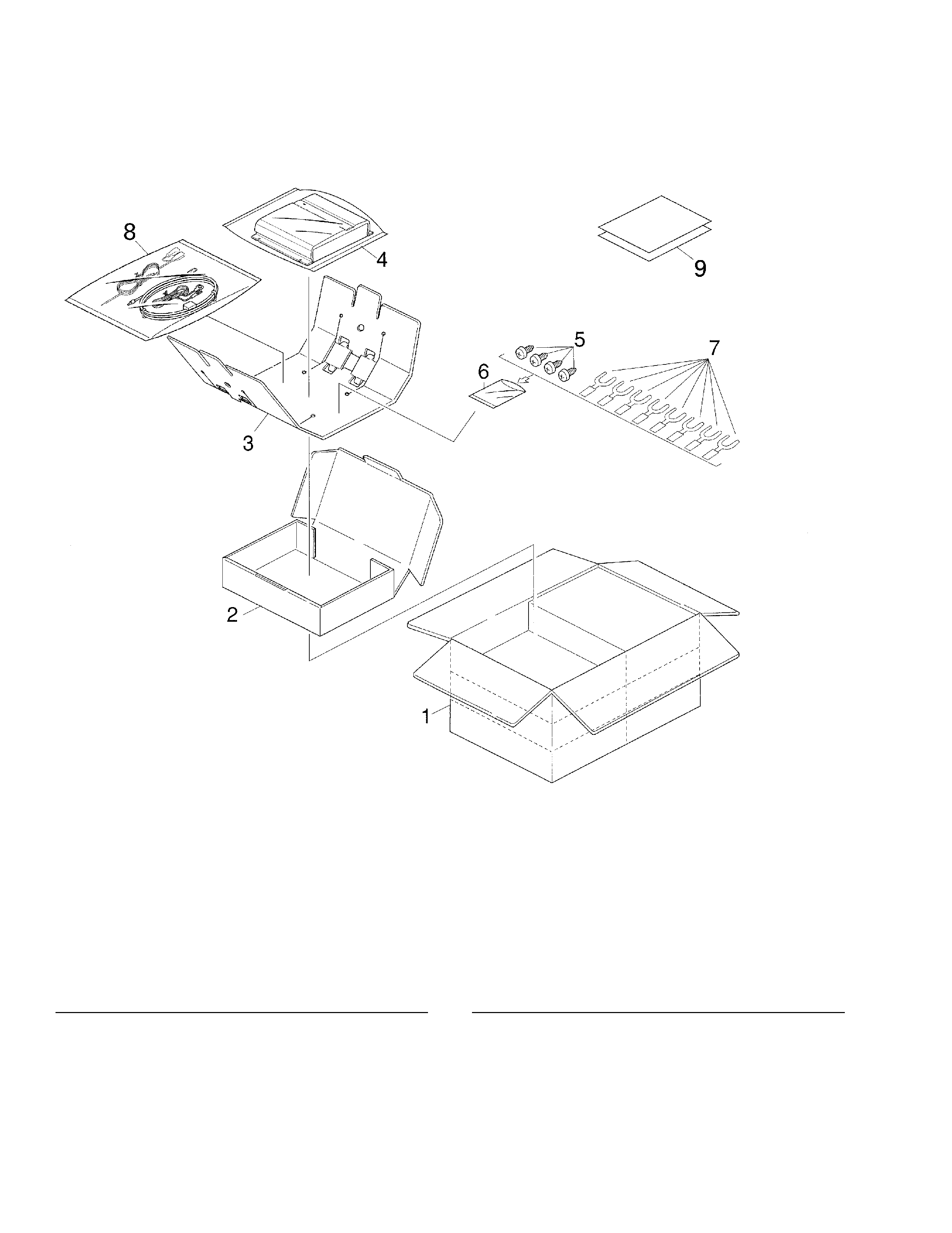
2. EXPLODED VIEWS AND PARTS LIST
2.1. PACKING
1 Contain Box
See Contrast table (2)
2 Carton
See Contrast table (2)
3 Protector
HHP0020
4 Polyethylene Bag
HEG0010
5 Screw(x4)
BYC40P180FZK
6 Polyethylene Bag
HEG0011
7 Terminal(x8)
See Contrast table (2)
8 Cord Assy
See Contrast table (2)
9-1 Owner's Manual
See Contrast table (2)
9-2 Owner's Manual
See Contrast table (2)
*
9-3 Warranty Card
HRY1070
*
9-4 Caution Card
See Contrast table (2)
*
9-5 Card
See Contrast table (2)
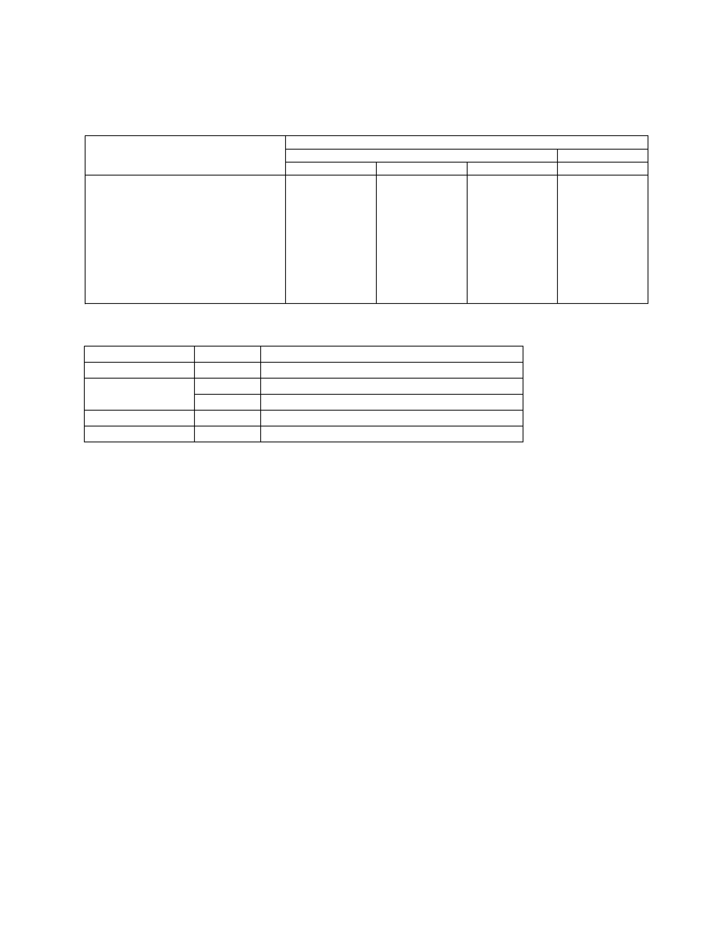
(1) PACKING SECTION PARTS LIST
Mark No. Description
Part No.
Mark No. Description
Part No.
NOTE:
- Parts marked by "*"are generally unavailable because they are not in our Master Spare Parts List.
- Screws adjacent to
mark on the product are used for disassembly.
Fig. 1
3
GM-X422, GM-X322
(2) CONTRAST TABLE
GM-X422/X1R/UC, GM-X422/X1R/ES, GM-X422/X1R/EW and GM-X322/X1R/UC are constructed the same except for the
following:
Part No.
GM-X422
GM-X322
Mark
No.
Symbol and Description
X1R/UC
X1R/ES
X1R/EW
X1R/UC
1
Contain Box
HHL0134
HHL0135
HHL0136
HHL0133
2
Carton
HHG0134
HHG0135
HHG0136
HHG0133
7
Terminal(x8)
HKC0001
HKC0003
HKC0003
HKC0003
8
Cord Assy
Not used
HDE4419
HDE4419
Not used
9-1
Owner's Manual
HRD0048
HRD0045
HRD0047
HRD0046
9-2
Owner's Manual
Not used
HRD0049
Not used
Not used
*
9-3
Warranty Card
HRY1070
Not used
HRY1087
Not used
*
9-4
Caution Card
HRP0006
Not used
Not used
Not used
*
9-5
Card
Not used
Not used
Not used
ARY1048
- Owner's Manual
Model
Part No.
Language
GM-X422/X1R/UC
HRD0048
English, French
GM-X422/X1R/ES
HRD0045
English, Spanish
HRD0049
Arabic, Portuguese(B)
GM-X422/X1R/EW
HRD0047
English, French, German, Dutch, Spanish, Italian
GM-X322/X1R/UC
HRD0046
English, French
4
GM-X422, GM-X322
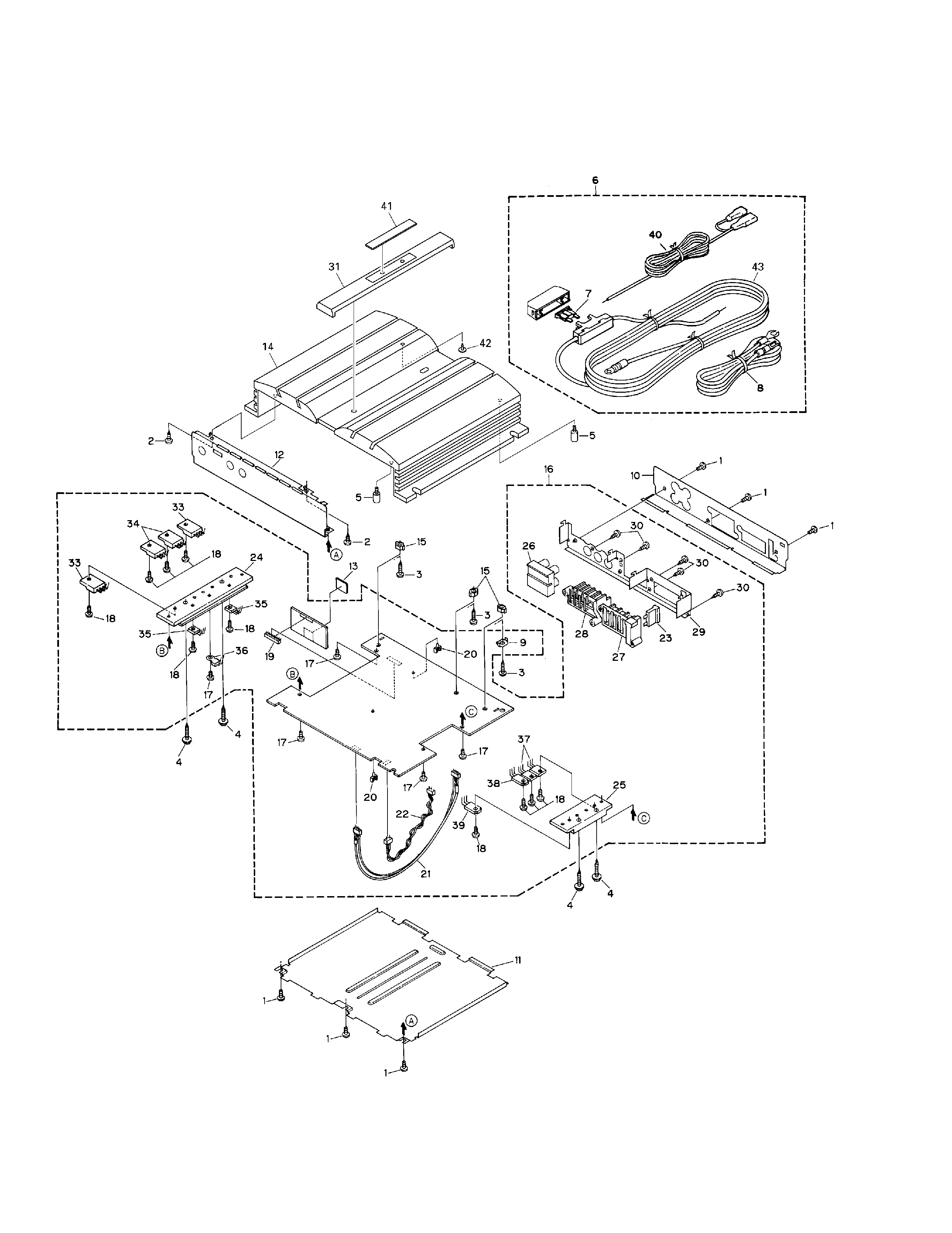
2.2. EXTERIOR
Fig. 2
5
GM-X422, GM-X322
1 Screw
BSZ30P050FZK
2 Screw(M3x6)
CBA1320
3 Screw(M3x12)
CBA1323
4 Screw
CBA1382
5 Screw
HBA0006
6 Cord Assy
See Contrast table (2)
7 Fuse(15A)
See Contrast table (2)
8 Ground Wire(Black)
See Contrast table (2)
9 Holder
CNC5399
10 Panel
See Contrast table (2)
11 Case
HNB0016
12 Panel
See Contrast table (2)
13 Spacer
HNM0026
14 Heat Sink
See Contrast table (2)
15 Spacer
HNV3975
16 Amp Unit
See Contrast table (2)
17 Screw
BMS30P060FZK
18 Screw
BMS30P080FMC
19 Plug(CN855)
CKS1618
20 Clamper
HNV0006
21 Connector(CN853)
HDE4418
22 Cord(CN551)
HDE4610
23 Fuse(20A)
HEK0020
24 Heat Sink(Sub Heat Sink) HNR0053
25 Heat Sink(Sub Heat Sink) HNR0054
26 Pin Jack(CN851)
See Contrast table (2)
27 Terminal(CN901)
See Contrast table (2)
28 Terminal(CN651)
See Contrast table (2)
29 Holder
HNC0006
30 Screw
PPZ30P060FZK
31 Plate Unit
See Contrast table (2)
32 ·····
33 Transistor(Q561,562)
2SD2438
34 Transistor(Q563,564)
2SB1587
35 Transistor(Q555,556)
2SD2343
36 Thermistor(TH901)
CCX1013
37 FET(Q905,906)
IRFIZ44N
38 Diode(D907)
ESAC25M-02C
39 Diode(D910)
ESAC25M-02N
40 System Remote Control See Contrast table (2)
41 Badge Unit
See Contrast table (2)
42 Light Pipe Unit
HXA0182
43 Special Red Battery Wire See Contrast table (2)
(1) EXTERIOR SECTION PARTS LIST
Mark No. Description
Part No.
Mark No. Description
Part No.
(2) CONTRAST TABLE
GM-X422/X1R/UC, GM-X422/X1R/ES, GM-X422/X1R/EW and GM-X322/X1R/UC are constructed the same except for the
following:
Part No.
GM-X422
GM-X322
Mark
No.
Symbol and Description
X1R/UC
X1R/ES
X1R/EW
X1R/UC
6
Cord Assy
Not used
HDE4453
HDE4453
Not used
7
Fuse(15A)
Not used
HEK0015
HEK0015
Not used
8
Ground Wire(Black)
Not used
HDE4455
HDE4455
Not used
10
Panel
HNB0055
HNB0073
HNB0056
HNB0058
12
Panel
HNB0050
HNB0072
HNB0072
HNB0051
14
Heat Sink
HNR0092
HNR0099
HNR0099
HNR0096
16
Amp Unit
HWH0059
HWH0057
HWH0056
HWH0058
26
Pin Jack(CN851)
HKB0006
HKB0005
HKB0005
HKB0003
27
Pin Jack(CN901)
HKE0002
HKE0001
HKE0001
HKE0001
28
Pin Jack(CN651)
HKE0008
HKE0007
HKE0003
Not used
31
Plate Unit
HXA0166
HXA0163
HXA0163
HXA0163
40
System Remote Control
Not used
HDE0007
HDE0007
Not used
41
Badge Unit
HXA0168
HXA0164
HXA0164
HXA0164
43
Special Red Battery Wire
Not used
HDE4454
HDE4454
Not used