PIONEER CORPORATION
4-1, Meguro 1-Chome, Meguro-ku, Tokyo 153-8654, Japan
PIONEER ELECTRONICS (USA) INC.
P.O.Box 1760, Long Beach, CA 90801-1760 U.S.A.
PIONEER EUROPE NV
Haven 1087 Keetberglaan 1, 9120 Melsele, Belgium
PIONEER ELECTRONICS ASIACENTRE PTE.LTD. 253 Alexandra Road, #04-01, Singapore 159936
C PIONEER CORPORATION 2002
K-ZZY. NOV. 2002 Printed in Japan
BRIDGEABLE POWER AMPLIFIER
GM-X372
XH/UC,XH/EW,XH/ES
For details, refer to "Important symbols for good services".
ORDER NO.
CRT3006
Service
Manual
GM-X372/XH/UC
BRIDGEABLE
2-CH POWER AMPLIFIER
BRIDGED
2
1
234
12
34
F
E
D
C
B
A
GM-X372/XH/UC
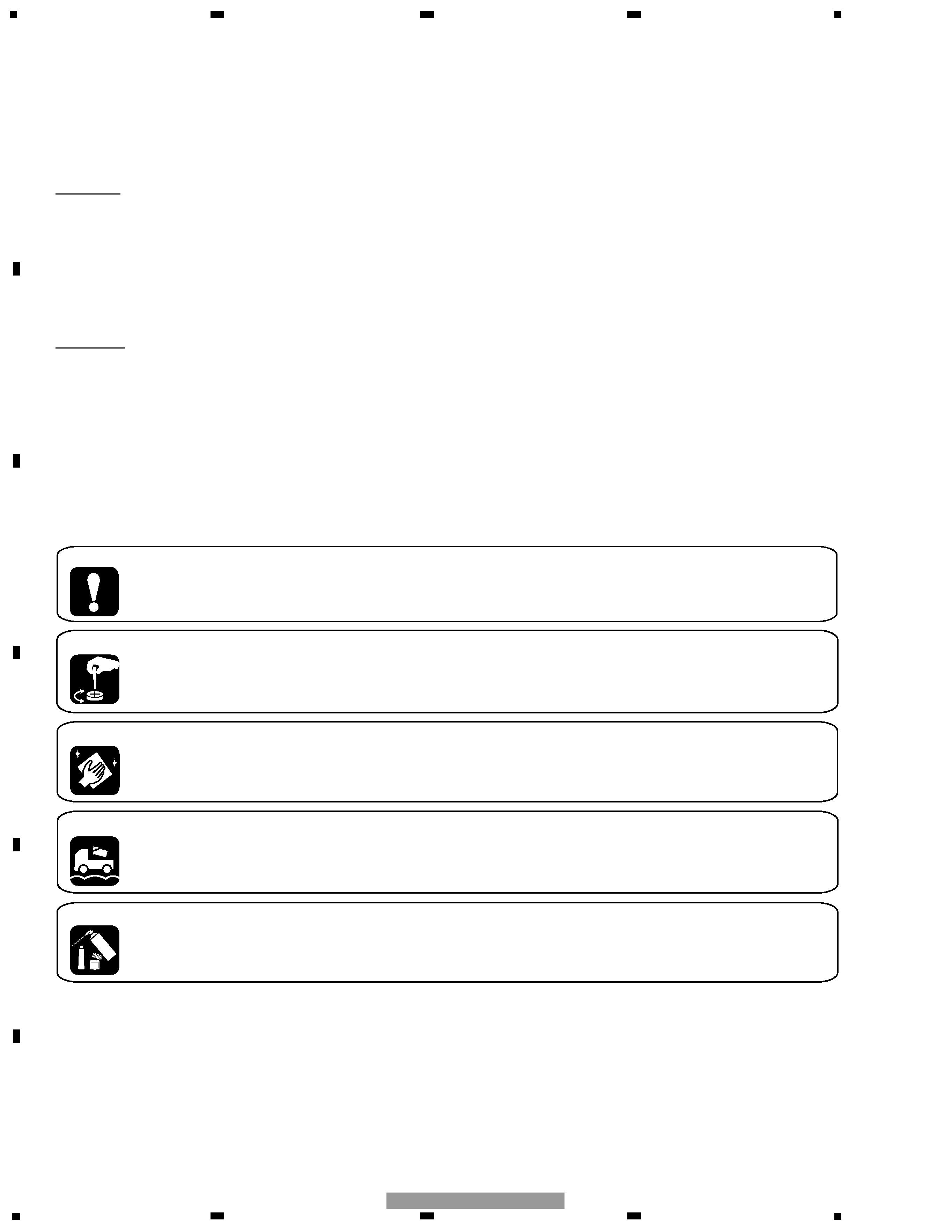
[ Important symbols for good services ]
In this manual, the symbols shown-below indicate that adjustments, settings or cleaning should be made securely.
When you find the procedures bearing any of the symbols, be sure to fulfill them:
2. Adjustments
To keep the original performances of the product, optimum adjustments or specification confirmation is indispensable.
In accordance with the procedures or instructions described in this manual, adjustments should be performed.
3. Cleaning
For optical pickups, tape-deck heads, lenses and mirrors used in projection monitors, and other parts requiring cleaning,
proper cleaning should be performed to restore their performances.
5. Lubricants, glues, and replacement parts
Appropriately applying grease or glue can maintain the product performances. But improper lubrication or applying
glue may lead to failures or troubles in the product. By following the instructions in this manual, be sure to apply the
prescribed grease or glue to proper portions by the appropriate amount.For replacement parts or tools, the prescribed
ones should be used.
4. Shipping mode and shipping screws
To protect the product from damages or failures that may be caused during transit, the shipping mode should be set or
the shipping screws should be installed before shipping out in accordance with this manual, if necessary.
1. Product safety
You should conform to the regulations governing the product (safety, radio and noise, and other regulations), and
should keep the safety during servicing by following the safety instructions described in this manual.
CAUTION
This service manual is intended for qualified service technicians; it is not meant for the casual do-it-yourselfer.
Qualified technicians have the necessary test equipment and tools, and have been trained to properly and safely repair
complex products such as those covered by this manual.
Improperly performed repairs can adversely affect the safety and reliability of the product and may void the warranty.
If you are not qualified to perform the repair of this product properly and safely, you should not risk trying to do so
and refer the repair to a qualified service technician.
WARNING
This product contains lead in solder and certain electrical parts contain chemicals which are known to the state of
California to cause cancer, birth defects or other reproductive harm.
Health & Safety Code Section 25249.6 - Proposition 65
SAFETY INFORMATION
- GM-X372/XH/UC

3
5
6
7
8
F
E
D
C
B
A
5
6
7
8
GM-X372/XH/UC
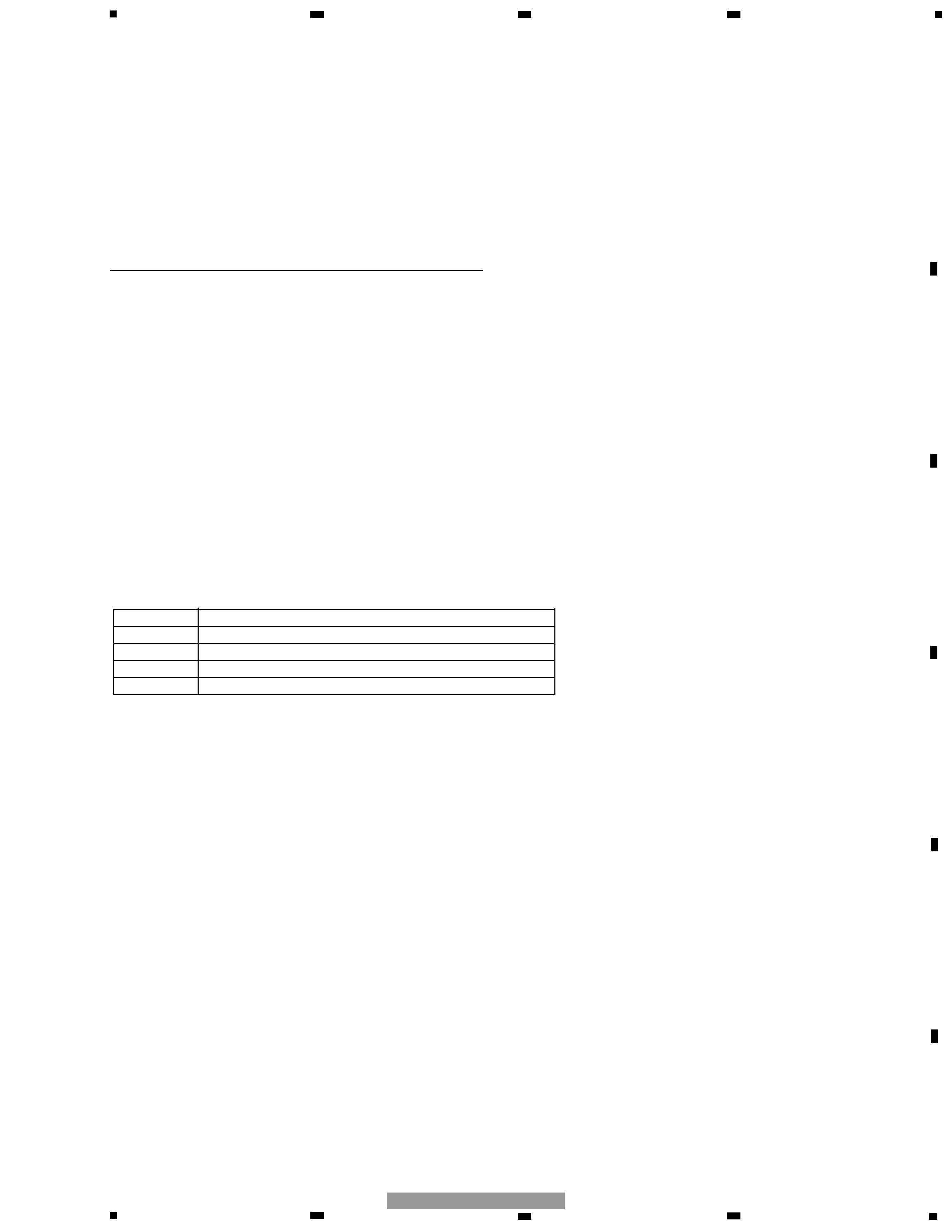
1. SPECIFICATIONS
CONTENTS
SAFETY INFORMATION ............................................2
1. SPECIFICATIONS........................................................3
2. EXPLODED VIEWS AND PARTS LIST .......................4
2.1 PACKING ...............................................................4
2.2 EXTERIOR .............................................................6
3. SCHEMATIC DIAGRAM .............................................8
3.1 OVERALL CONNECTION DIAGRAM(GUIDE PAGE)....8
4. PCB CONNECTION DIAGRAM ................................14
4.1 AMP UNIT...........................................................14
5. ELECTRICAL PARTS LIST ........................................18
6. ADJUSTMENT..........................................................19
7. GENERAL INFORMATION .......................................20
7.1 DIAGNOSIS ........................................................20
7.1.1 DISASSEMBLY .........................................20
7.1.2 CONNECTOR FUNCTION DESCRIPTION .......21
7.2 IC ........................................................................22
8. OPERATIONS............................................................23
Power source .............................................................................................................. 14.4 V DC (10.8 -- 15.1 V allowable)
Grounding system ............................................................................................................................................ Negative type
Current consumption ........................................................................................................ 14.4 A (at continuous power, 4
)
Average current drawn* ............................................................................................................ 5.0 A (4
for two channels)
7.5 A (4
for one channel)
Fuse ............................................................................................................................................................................ 25 A
× 1
Dimensions ......................................................................................................................... 255 (W)
× 50 (H) × 169 (D) mm
[10 (W)
× 2 (H) × 6-5/8 (D) in]
Weight ..................... .................................................................................... 2.0 kg (4.4 lbs) (Leads for wiring not included)
Maximum power output ...................... .............................................................................................. 100 W
× 2 / 240 W × 1
Continuous power output ..................... ...................................... 50 W
× 2 (at 14.4 V, 4 , 20 -- 20,000 Hz, 0.15% THD)
120 W
× 1 (at 14.4 V, 4 , 20 -- 20,000 Hz, 0.8% THD)
60 W
× 2 (at 14.4 V, 2 , 20 -- 20,000 Hz, 0.8% THD)
Load impedance ............................................................................................................................ 4
(2 -- 8 allowable)
(Bridge connection: 4 -- 8
allowable)
Frequency response ............................................................................................................ 10 -- 50,000 Hz (+0 dB, 1 dB)
Signal-to-noise ratio ..................... .................................................................................................. 100 dB (IHFA network)
Distortion .............................................................................................................................................. 0.008% (10 W, 1 kHz)
Separation ......................................................................................................................................................... 60 dB (1 kHz)
Low pass filter ................................................................................................................................ Cut off frequency: 80 Hz
Cut off slope: 12 dB/oct
Maximum input level/impedance .................................................................................... RCA: 6.5 V/22 k
(0.2 -- 6.5 V)
Speaker: 26 V/40 k
(0.8 -- 26 V)
Note:
· Specifications and the design are subject to possible modification without notice
due to improvements.
*Average current drawn
· The average current drawn is nearly the maximum current drawn by this unit
when an audio signal is input. Use this value when working out total current
drawn by multiple power amplifiers.
Backup current ................................................................................................................................................. 3.0 mA or less
4
1
234
12
34
F
E
D
C
B
A
GM-X372/XH/UC
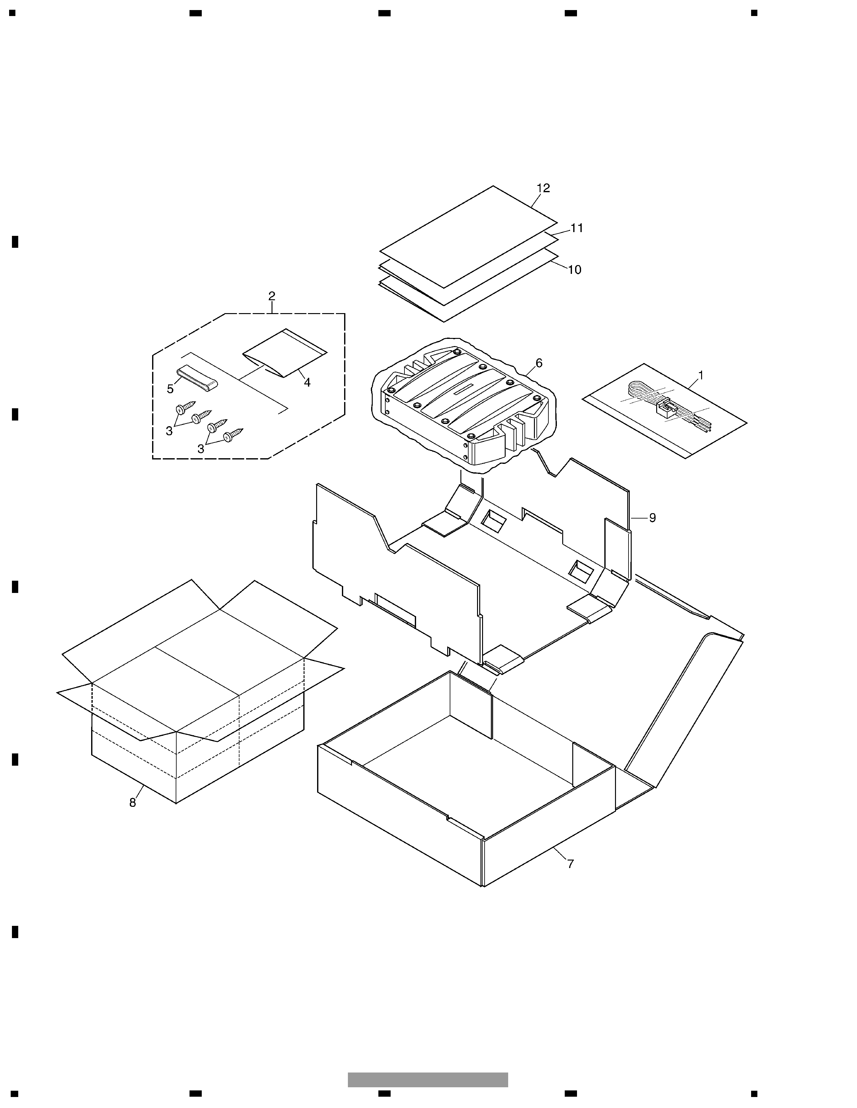
2. EXPLODED VIEWS AND PARTS LIST
2.1 PACKING
5
5
6
7
8
F
E
D
C
B
A
5
6
7
8
GM-X372/XH/UC
1 Cord
HDE0044
2 Screw Assy
HEA0058
3 Screw
BYC40P180FZK
4 Polyethylene Bag
HEG0011
5 Cover
HNS0101
6 Polyethylene Bag
HEG0013
7 Carton
HHG0341
8 Contain Box
HHL0341
9 Protector
HHP0170
10 Owner's Manual(UC)
HRD0226
Owner's Manual(EW)
HRD0227
Owner's Manual(ES)
HRD0228
11 Owner's Manual(ES)
HRD0229
*
12 Warranty Card
HRY1157
- PACKING SECTION PARTS LIST
Mark No. Description
Part No.
NOTE:
- Parts marked by "*" are generally unavailable because they are not in our Master Spare Parts List.
- Screws adjacent to
mark on the product are used for disassembly.
- For the applying amount of lubricants or glue, follow the instructions in this manual.
( In the case of no amount instructions, apply as you think it appropriate.)
- Owner's Manual
Part No.
Language
HRD0226
English, French
HRD0227
English, French, Spanish, German, Italian, Dutch
HRD0228
English, Spanish
HRD0229
Portuguese(B), Arabic