ORDER NO.
PIONEER CORPORATION 4-1, Meguro 1-chome, Meguro-ku, Tokyo 153-8654, Japan
PIONEER ELECTRONICS (USA) INC. P.O. Box 1760, Long Beach, CA 90801-1760, U.S.A.
PIONEER EUROPE NV Haven 1087, Keetberglaan 1, 9120 Melsele, Belgium
PIONEER ELECTRONICS ASIACENTRE PTE. LTD. 253 Alexandra Road, #04-01, Singapore 159936
PIONEER CORPORATION 2004
CRT3313
XM SATELLITE DIGITAL TUNER
GEX-M7047XMZH
/XN/UC
GEX-M7747XMZH/XN/UC
GEX-M7547XMZH/XN/UC
K-ZZA. JUNE 2004 printed in Japan
HONDA
-
-
-
- This service manual should be used together with the manual(s) listed below.
For the parts numbers, adjustments, etc. which are not shown in this manual,refer to the following
manual(s).
VEHICLE
DESTINATION
PRODUCED AFTER
HONDA PART No.
ID No.
PIONEER MODEL No.
ODYSSEY
U.S.A.
August 2004
39820-SHJ-A010-M1
·····
GEX-M7047XMZH/XN/UC
ACCORD
U.S.A.
August 2004
39820-SDA-L214-M1
·····
GEX-M7747XMZH/XN/UC
ACCORD
U.S.A.
July 2004
39820-SDA-L214-M1
·····
GEX-M7547XMZH/XN/UC
Model No.
Order No.
Mech.Module
Remarks
GEX-M7027XMZH/XN/UC
CRT3005
GEX-M7047XMZH/XN/UC
2
1234
123
4
C
D
F
A
B
E
EXTERIOR(Page 6)
- EXTERIOR SECTION PARTS LIST
Mark No.
Description
GEX-M7027XMZH/XN/UC GEX-M7047XMZH/XN/UC GEX-M7747XMZH/XN/UC GEX-M7547XMZH/XN/UC
4
Main Unit
CWM8561
CWM9687
CWM9687
CWM9687
18
Digital Unit
CWX2749
CWX3074
CWX3074
CWX3074
24
Case Unit
CXB9640
CXC2936
CXC2160
CXC2160
EXPLODED VIEWS AND PARTS LIST
PACKING(Page 4)
- PACKING SECTION PARTS LIST
Mark No.
Description
GEX-M7027XMZH/XN/UC GEX-M7047XMZH/XN/UC GEX-M7747XMZH/XN/UC GEX-M7547XMZH/XN/UC
1
Contain Box
CHL4928
CHL5218
CHL5314
CHL5291
5
Protector
CHP2655
CHP2655
CHP2726
CHP2726
*
6
Card
CRL2374
Not used
Not used
CRL2687
ELECTRICAL PARTS LIST(Page 36)
Digital Unit
Symbol and Description
GEX-M7027XMZH/XN/UC GEX-M7047XMZH/XN/UC GEX-M7747XMZH/XN/UC GEX-M7547XMZH/XN/UC
IC202 IC
STA-400
STA-400A
STA-400A
STA-400A
IC203 IC
K4S280832D-TL1H
K4S280832F-TC75
K4S280832F-TC75
K4S280832F-TC75
IC206 IC
STA-450
STA-450AP
STA-450AP
STA-450AP
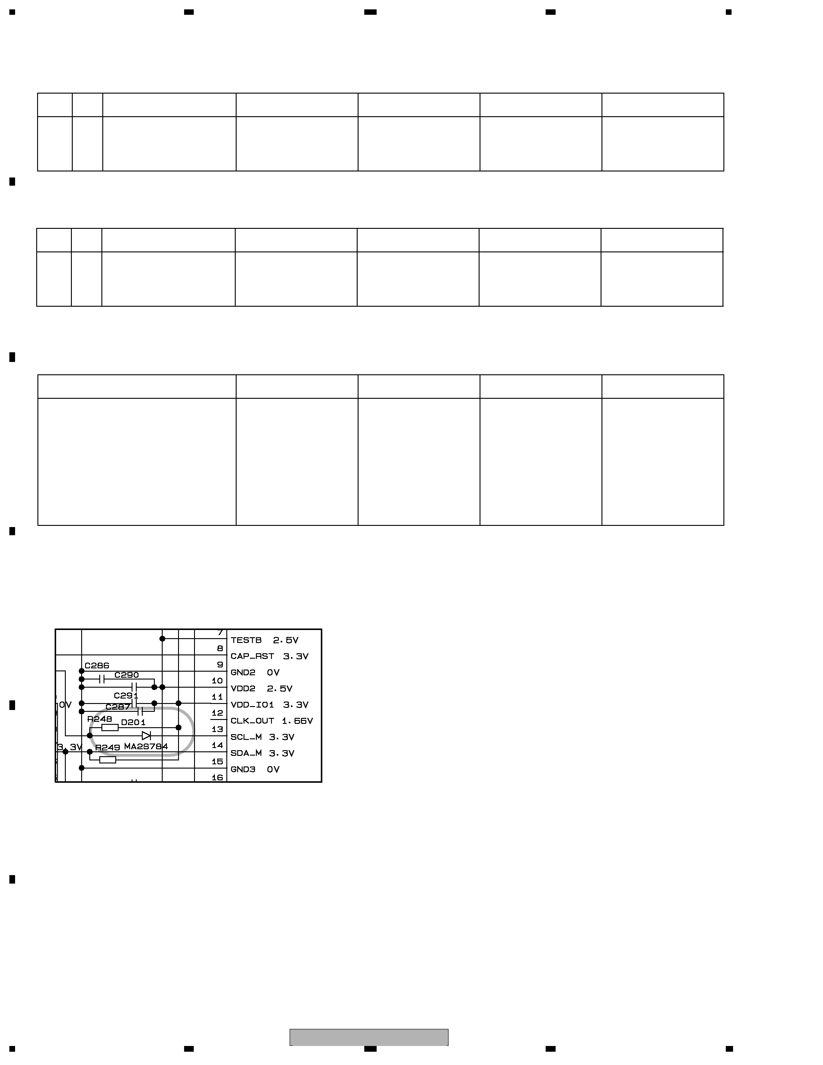
D201 Diode
Not used
MA2S784
MA2S784
MA2S784
R248
RS1/16SS103J
RS1/16SS472J
RS1/16SS472J
RS1/16SS472J
R249
RS1/16SS103J
RS1/16SS472J
RS1/16SS472J
RS1/16SS472J
*:Non spare part
R1
R1
IC206
100P
100P
Page 27 5-C
GEX-M7047XMZH/XN/UC
3
5
678
56
7
8
C
D
F
A
B
E
Main Unit
Symbol and Description
GEX-M7027XMZH/XN/UC GEX-M7047XMZH/XN/UC GEX-M7747XMZH/XN/UC GEX-M7547XMZH/XN/UC
IC701 IC
PD5818A
PEG048A
PEG048A
PEG048A
IC852 IC
S-816A25AMC-BAA
TA48018S
TA48018S
TA48018S
Q852 Transistor
2SB1185
Not used
Not used
Not used
D851 Diode
S2G-6600
Not used
Not used
Not used
D902 Diode
MPG06G-6415G50
S2G-6600
S2G-6600
S2G-6600
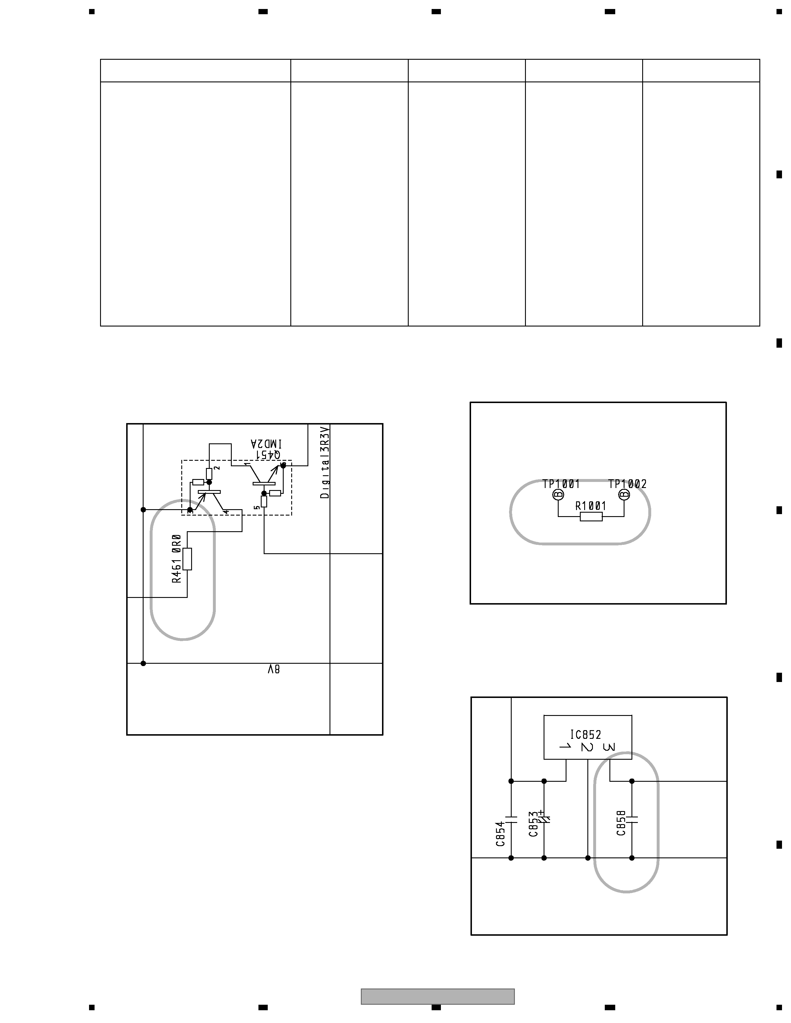
R461
Not used
RS1/16S0R0J
RS1/16S0R0J
RS1/16S0R0J
R718
RS1/16S223J
RS1/16S104J
RS1/16S104J
RS1/16S104J
R720
RS1/16S223J
RS1/16S473J
RS1/16S473J
RS1/16S473J
R1001
Not used
RS1/16S0R0J
RS1/16S0R0J
RS1/16S0R0J
C853
CSZS4R7M10
CSZS330M6R3
CSZS330M6R3
CSZS330M6R3
C858
Not used
CKSRYB104K16
CKSRYB104K16
CKSRYB104K16
C906
CEAT102M16
CEAT221M25
CEAT221M25
CEAT221M25
R1
R01
Page 15 5-F
R1
R01
Page 15 5-F
R1
R01
Page 15 5-F
R1
R01
Page 15 5-F
0R0
Page 15
MUTE
Page 12 3-B
GEX-M7047XMZH/XN/UC
4
1234
123
4
C
D
F
A
B
E
Capacitor
Connector
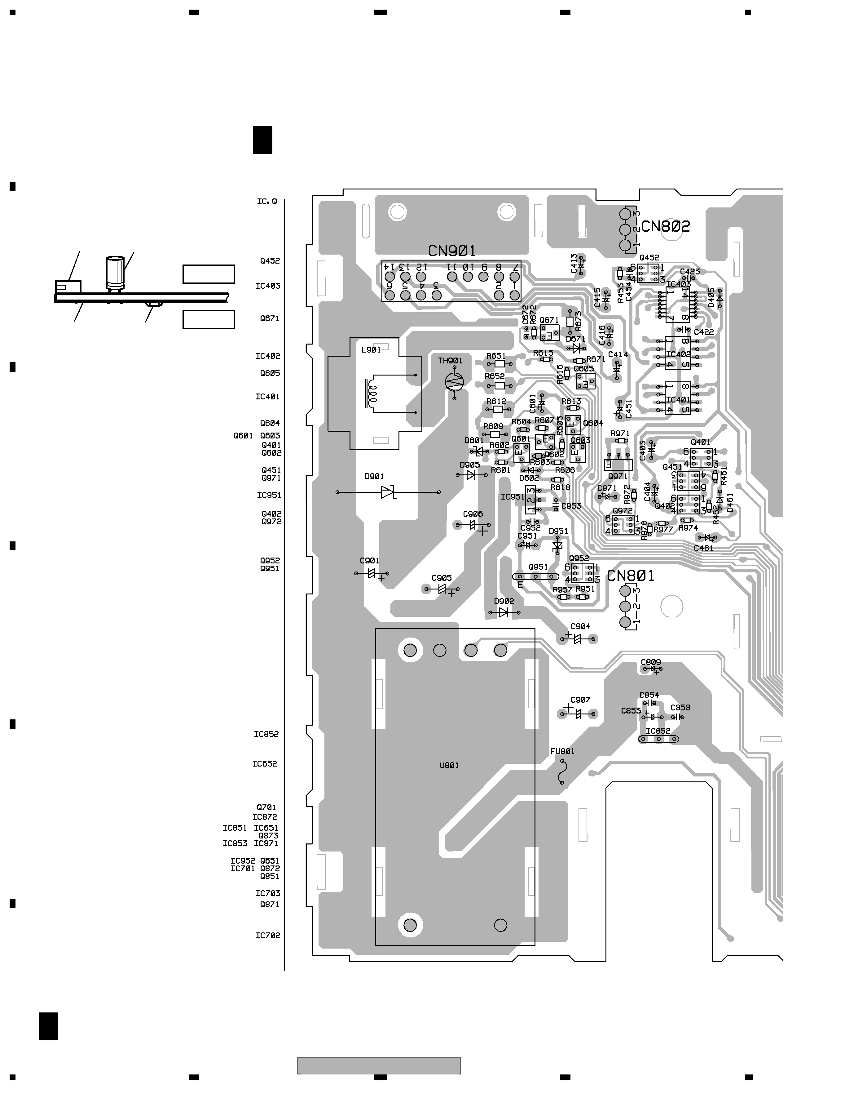
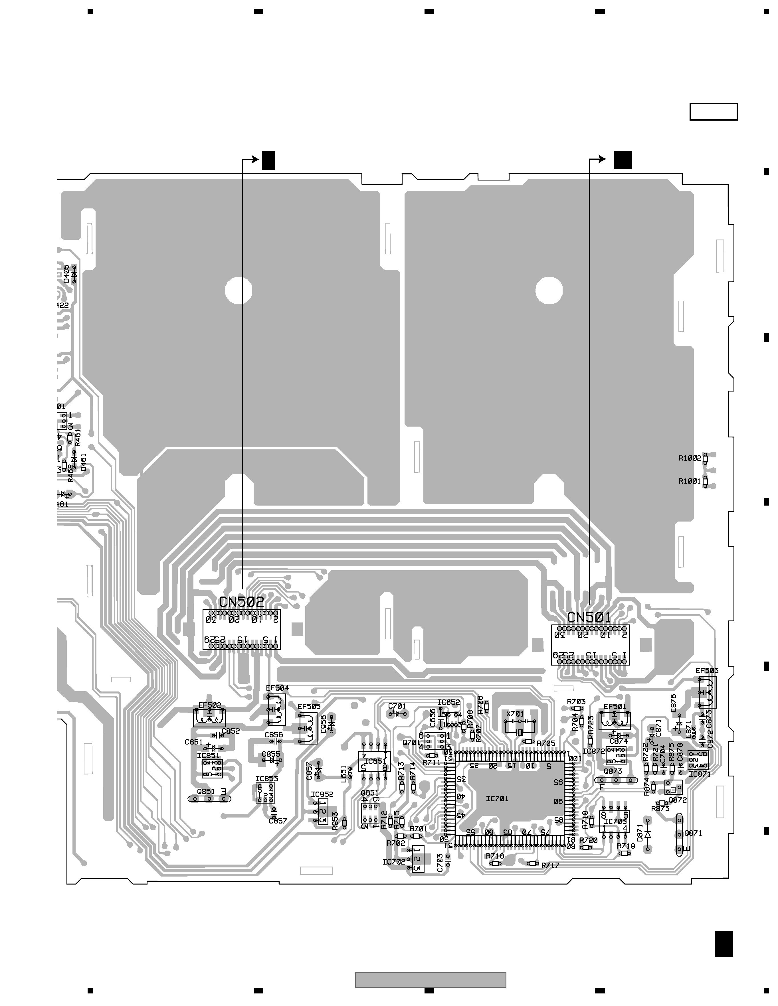
P.C.Board
Chip Part
MAIN UNIT
SIDE B
SIDE A
NOTE FOR PCB DIAGRAMS
1.The parts mounted on this PCB
include all necessary parts for
several destination.
For further information for
respective destinations, be sure
to check with the schematic dia-
gram.
2.Viewpoint of PCB diagrams
A F
A F
65
43
21
123
PCB CONNECTION DIAGRAM
MAIN UNIT
GEX-M7047XMZH/XN/UC
5
5
678
56
7
8
C
D
F
A
B
E
SIDE A
A F
CN201
B CN2
C F