PIONEER CORPORATION
4-1, Meguro 1-Chome, Meguro-ku, Tokyo 153-8654, Japan
PIONEER ELECTRONICS (USA) INC.
P.O.Box 1760, Long Beach, CA 90801-1760 U.S.A.
PIONEER EUROPE NV
Haven 1087 Keetberglaan 1, 9120 Melsele, Belgium
PIONEER ELECTRONICS ASIACENTRE PTE.LTD. 253 Alexandra Road, #04-01, Singapore 159936
C PIONEER CORPORATION 2003
K-ZZD. APR. 2003 Printed in Japan
ORDER NO.
CRT3049
MULTI-CD CONTROL DSP HIGH POWER CD/MP3/WMA/MD PLAYER WITH FM/AM TUNER
FH-P9200MP
ES
Service
Manual
- This service manual should be used together with the following manual(s):
Model No.
Order No.
Mech. Module Remarks
CX-3057
CRT3026
S10MP3
CD Mech. Module:Circuit Description, Mech.Description, Disassembly
CX-1020
CRT2653
MD4LP
MD Mech. Module:Circuit Description, Mech.Description, Disassembly
- Dolby noise reduction manufactured under license from Dolby Laboratories Licensing Corporation.
"Dolby" and the double-D symbol are trademarks of Dolby Laboratories Licensing Corporation.
FH-P9200MP/ES
For details, refer to "Important symbols for good services".
2
1
234
12
34
F
E
D
C
B
A
FH-P9200MP/ES
SAFETY INFORMATION
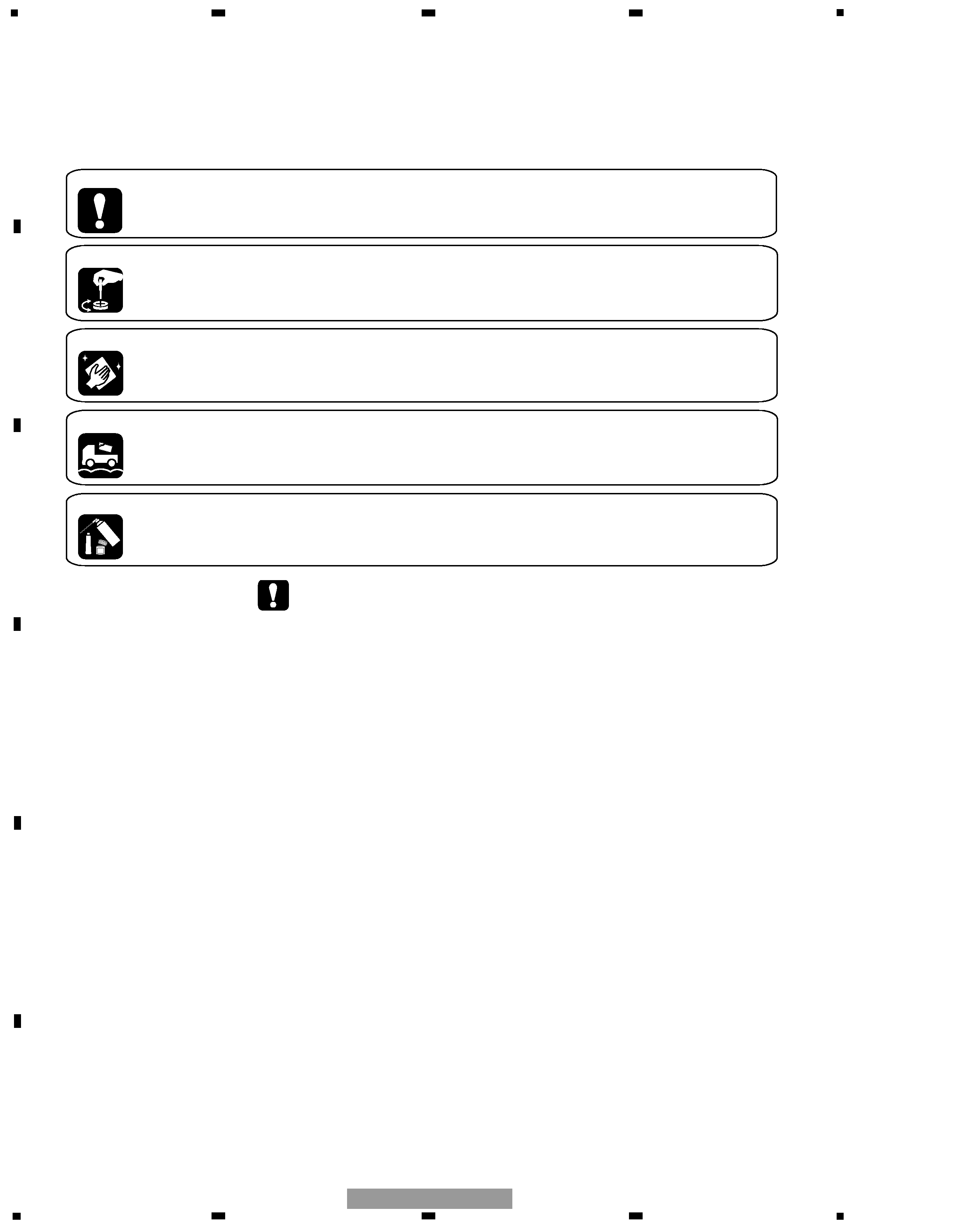
[ Important symbols for good services ]
In this manual, the symbols shown-below indicate that adjustments, settings or cleaning should be made securely.
When you find the procedures bearing any of the symbols, be sure to fulfill them:
2. Adjustments
To keep the original performances of the product, optimum adjustments or specification confirmation is indispensable.
In accordance with the procedures or instructions described in this manual, adjustments should be performed.
3. Cleaning
For optical pickups, tape-deck heads, lenses and mirrors used in projection monitors, and other parts requiring cleaning,
proper cleaning should be performed to restore their performances.
5. Lubricants, glues, and replacement parts
Appropriately applying grease or glue can maintain the product performances. But improper lubrication or applying
glue may lead to failures or troubles in the product. By following the instructions in this manual, be sure to apply the
prescribed grease or glue to proper portions by the appropriate amount.For replacement parts or tools, the prescribed
ones should be used.
4. Shipping mode and shipping screws
To protect the product from damages or failures that may be caused during transit, the shipping mode should be set or
the shipping screws should be installed before shipping out in accordance with this manual, if necessary.
1. Product safety
You should conform to the regulations governing the product (safety, radio and noise, and other regulations), and
should keep the safety during servicing by following the safety instructions described in this manual.
- CD section precaution
1. Before disassembling the unit, be sure to turn off
the power. Unplugging and plugging the connectors
during power-on mode may damage the ICs inside
the unit.
2. To protect the pickup unit from electrostatic discharge
during servicing, take an appropriate treatment
(shorting-solder) by referring to "the DISASSEMBLY"
on page 88.
3. After replacing the pickup unit, be sure to check the
grating. (See p.78.)
- MD section precaution
1. Remove all loaded discs (MD) from the product.
2. Before disassembling the product, be sure to turn off
the power.
3. When reassembling the product, be sure to restore the
wire arrangement.
4. During servicing, be careful not to apply electrostatic
current to any circuits (including ICs). Use a solder iron
with the iron tip grounded. Use antistatic-type tweezers
(not metal-type tweezers) because they may be shorted
to the device terminal.
This service manual is intended for qualified service technicians; it is not meant for the casual do-it-yourselfer.
Qualified technicians have the necessary test equipment and tools, and have been trained to properly and safely repair
complex products such as those covered by this manual.
Improperly performed repairs can adversely affect the safety and reliability of the product and may void the warranty.
If you are not qualified to perform the repair of this product properly and safely, you should not risk trying to do so
and refer the repair to a qualified service technician.

3
5
6
7
8
F
E
D
C
B
A
5
6
7
8
FH-P9200MP/ES
CONTENTS
SAFETY INFORMATION .............................................................................................................2
1. SPECIFICATIONS ........................................................................................................................4
2. EXPLODED VIEWS AND PARTS LIST........................................................................................6
2.1 PACKING ...............................................................................................................................6
2.2 EXTERIOR(1) .........................................................................................................................8
2.3 EXTERIOR(2) .......................................................................................................................10
2.4 CD MECHANISM MODULE................................................................................................12
2.5 MD MECHANISM MODULE...............................................................................................14
3. BLOCK DIAGRAM AND SCHEMATIC DIAGRAM....................................................................16
3.1 BLOCK DIAGRAM ...............................................................................................................16
3.2 OVERALL CONNECTION DIAGRAM(GUIDE PAGE) .........................................................18
3.3 FLAP PCB UNIT...................................................................................................................24
3.4 CD MECHANISM MODULE(GUIDE PAGE) .......................................................................26
3.5 MD MECHANISM MODULE(GUIDE PAGE) ......................................................................36
3.6 DSP UNIT ............................................................................................................................46
3.7 PANEL PCB UNIT ................................................................................................................48
4. PCB CONNECTION DIAGRAM.................................................................................................50
4.1 AUDIO AMP UNIT...............................................................................................................50
4.2 FLAP PCB UNIT...................................................................................................................54
4.3 CD MECHANISM MODULE................................................................................................56
4.4 MD MECHANISM MODULE...............................................................................................58
4.5 PANEL PCB UNIT ................................................................................................................61
4.6 DSP UNIT ............................................................................................................................62
5. ELECTRICAL PARTS LIST .........................................................................................................64
6. ADJUSTMENT ..........................................................................................................................76
6.1 CD ADJUSTMENT ..............................................................................................................76
6.2 CHECKING THE GRATING AFTER CHANGING THE PICKUP UNIT ................................78
6.3 MD ADJUSTMENT .............................................................................................................80
6.4 ERROR MODE(CD)..............................................................................................................83
6.5 TEST MODE(MD) ................................................................................................................84
6.6 SYSTEM MICROCOMPUTER TEST PROGRAM ...............................................................88
7. GENERAL INFORMATION ........................................................................................................88
7.1 DIAGNOSIS .........................................................................................................................88
7.1.1 DISASSEMBLY ..............................................................................................................88
7.1.2 CONNECTOR FUNCTION DESCRIPTION....................................................................95
7.2 IC ..........................................................................................................................................96
7.3 OPERATIONAL FLOW CHART..........................................................................................113
7.4 CLEANING.........................................................................................................................114
8. OPERATIONS ..........................................................................................................................115
4
1
234
12
34
F
E
D
C
B
A
FH-P9200MP/ES
1. SPECIFICATIONS
5
5
6
7
8
F
E
D
C
B
A
5
6
7
8
FH-P9200MP/ES