PIONEER CORPORATION
4-1, Meguro 1-Chome, Meguro-ku, Tokyo 153-8654, Japan
PIONEER ELECTRONICS (USA) INC.
P.O.Box 1760, Long Beach, CA 90801-1760 U.S.A.
PIONEER EUROPE NV
Haven 1087 Keetberglaan 1, 9120 Melsele, Belgium
PIONEER ELECTRONICS ASIACENTRE PTE.LTD. 253 Alexandra Road, #04-01, Singapore 159936
C PIONEER CORPORATION 2002
K-ZZU. JAN. 2002 Printed in Japan
ORDER NO.
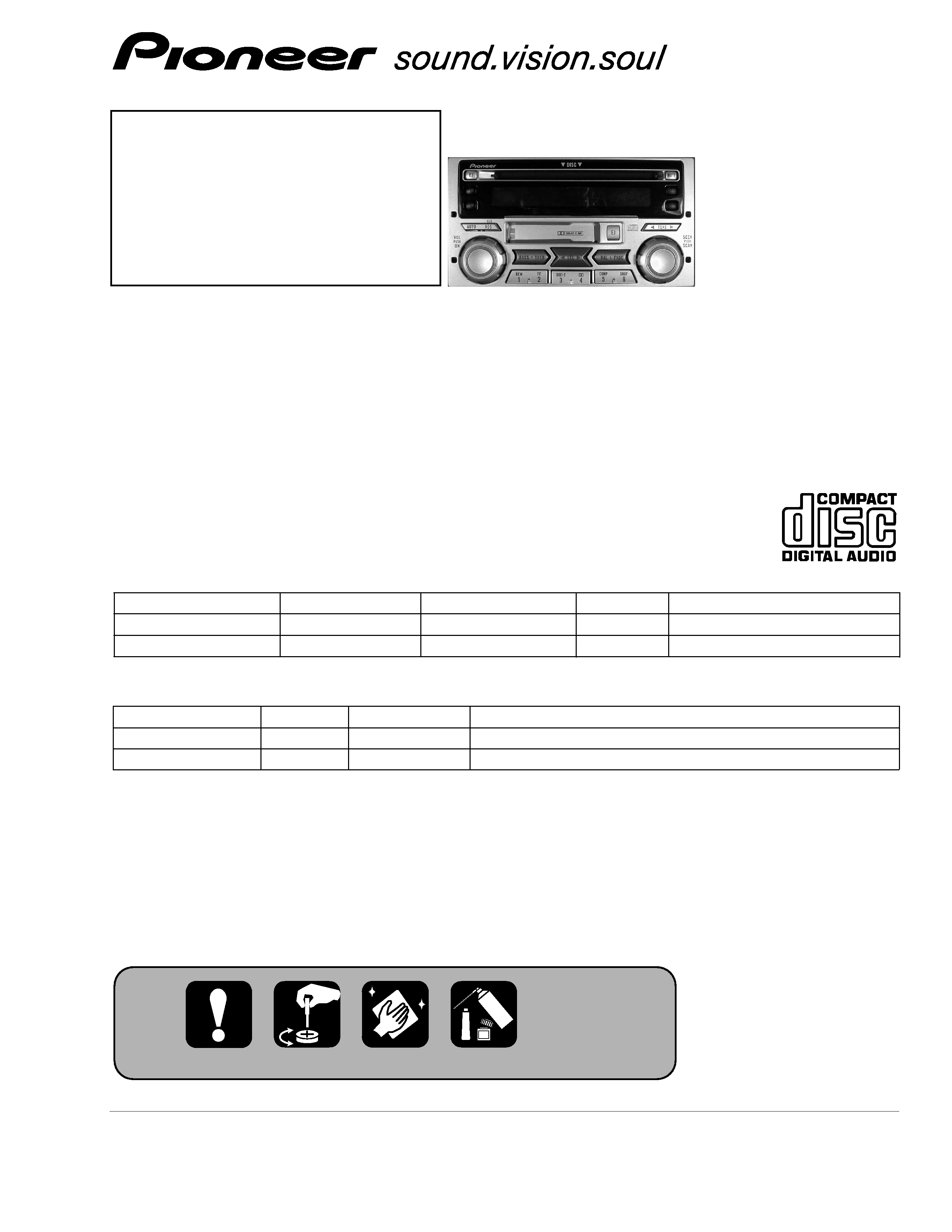
CRT2822
RECEIVER ASSY RADIO
FH-207 7ZF
X1H/UC
NOTE:
- Dolby noise reduction manufactured under license from Dolby Laboratories Licensing Corporation.
"Dolby" and the double-D symbol are trademarks of Dolby Laboratories Licensing Corporation.
FORD
VEHICLE
PRODUCED AFTER FORD PART No.
ID No.
PIONEER MODEL No.
FORD RANGER
2002
2L54-18C868-AB
-
FH-2077ZF/X1H/UC
FORD SPORT TRUCK
2002
2L2T-18C868-AA
-
FH-2177ZF/X1H/UC
- This service manual should be used together with the following manual(s):
Model No.
Order No.
Mech. Module
Remarks
CX-597
CRT1829
S7
CD Mech. Module:Circuit Description, Mech. Description, Disassembly
CX-1011
CRT2406
3L
Cassette Mech. Module:Mech. Description, Disassembly
For details, refer to "Important symbols for good services".
Service
Manual
FH-217 7ZF
X1H/UC
FH-2077ZF/X1H/UC
2
FH-2077ZF,2177ZF
[ Important symbols for good services ]
In this manual, the symbols shown-below indicate that adjustments, settings or cleaning should be made securely.
When you find the procedures bearing any of the symbols, be sure to fulfill them:
2. Adjustments
To keep the original performances of the product, optimum adjustments or specification confirmation is indispensable.
In accordance with the procedures or instructions described in this manual, adjustments should be performed.
3. Cleaning
For optical pickups, tape-deck heads, lenses and mirrors used in projection monitors, and other parts requiring cleaning,
proper cleaning should be performed to restore their performances.
5. Lubricants, glues, and replacement parts
Appropriately applying grease or glue can maintain the product performances. But improper lubrication or applying
glue may lead to failures or troubles in the product. By following the instructions in this manual, be sure to apply the
prescribed grease or glue to proper portions by the appropriate amount.For replacement parts or tools, the prescribed
ones should be used.
4. Shipping mode and shipping screws
To protect the product from damages or failures that may be caused during transit, the shipping mode should be set or
the shipping screws should be installed before shipping out in accordance with this manual, if necessary.
1. Product safety
You should conform to the regulations governing the product (safety, radio and noise, and other regulations), and
should keep the safety during servicing by following the safety instructions described in this manual.
CONTENTS
1. SAFETY INFORMATION ...........................................3
2. EXPLODED VIEWS AND PARTS LIST......................4
3. BLOCK DIAGRAM AND SCHEMATIC DIAGRAM ..10
4. PCB CONNECTION DIAGRAM ...............................38
5. ELECTRICAL PARTS LIST .......................................54
6. ADJUSTMENT ........................................................66
7. GENERAL INFORMATION ......................................76
7.1 DIAGNOSIS........................................................76
7.1.1 DISASSEMBLY .........................................76
7.1.2 CONNECTOR FUNCTION DESCRIPTION ..78
7.1.3 PCB LOCATION ........................................79
7.2 PARTS.................................................................80
7.2.1 IC ...............................................................80
7.2.2 DISPLAY ...................................................85
7.3 OPERATION FLOW CHART...............................86
7.4 CLEANING .........................................................87
8. OPERATIONS AND SPECIFICATIONS ...................88

3
FH-2077ZF,2177ZF
This service manual is intended for qualified service technicians; it is not meant for the casual do-it-yourselfer.
Qualified technicians have the necessary test equipment and tools, and have been trained to properly and safely repair
complex products such as those covered by this manual.
Improperly performed repairs can adversely affect the safety and reliability of the product and may void the warranty.
If you are not qualified to perform the repair of this product properly and safely, you should not risk trying to do so
and refer the repair to a qualified service technician.
1. SAFETY INFORMATION
4
FH-2077ZF,2177ZF
A
B
C
F
E
D
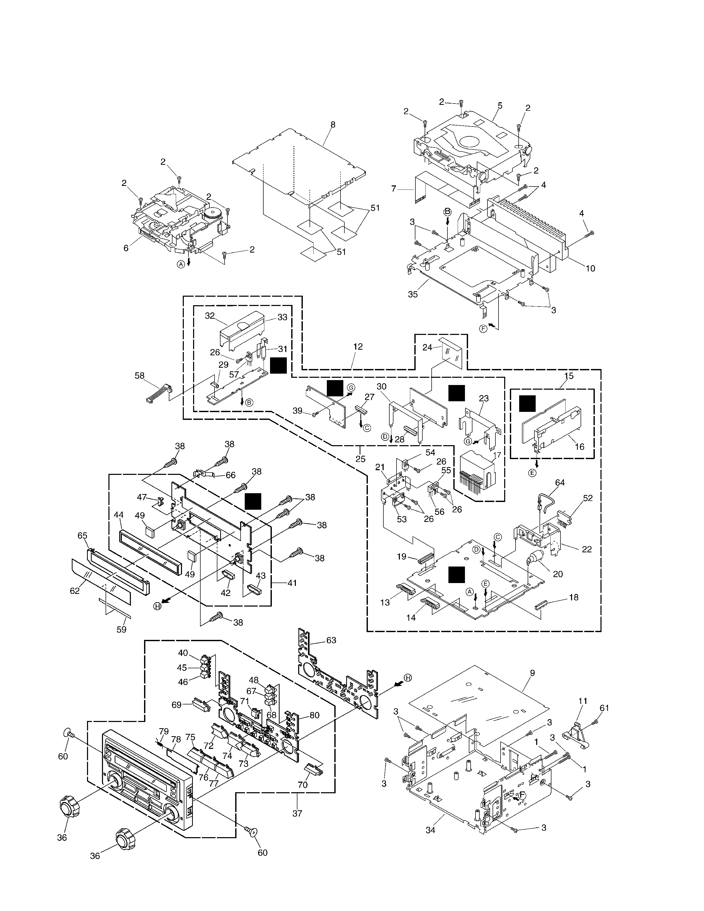
2. EXPLODED VIEWS AND PARTS LIST
2.1 EXTERIOR

5
FH-2077ZF,2177ZF
1 Screw
BMZ26P250FMC
2 Screw
BSZ26P050FMC
3 Screw
BSZ30P050FMC
4 Screw
BSZ30P120FMC
5 CD Mechanism Module(S7F VA) CXK5028
6 Cassette Mechanism Module EXK4260
7 Connector
CDE5462
8 Case
HNB2059
9 Insulator
HNM0089
10 Heat Sink
HNR1418
11 Rail Guide
HNV4897
12 Mother Unit(FH-2077ZF) HWM0072
Mother Unit(FH-2177ZF) HWM0081
13 Plug (CN952)
CKS3537
14 Plug (CN953)
CKS3538
15 Tuner Unit
CWE1428
16 Holder
CNC6122
17 Connector (CN901)
HKM1237
18 Connector (CN702)
CKS3568
19 Connector (CN701)
HKS2256
20 Antenna (CN402)
HKX1054
21 Holder
HNC6458
22 Holder
HNC6459
23 Holder
HNC6470
*
24 Insulator
HNM5228
25 Compound Unit(FH-2077ZF) HWM0074
Compound Unit(FH-2177ZF)
HWM0082
26 Screw
BMZ26P060FMC
27 Plug (CN1001)
CKS1621
28 Plug (CN201)
CKS1622
29 Connector(CN1051)
HKS3129
*
30 Holder
HNC6457
31 Holder
HNC6650
32 Shield
HNC6930
*
33 Insulator
HNM5229
34 Chassis Unit
HXA8841
35 Chassis Unit
HXA8842
36 Knob Assy
CXB8377
37 Grille Unit
CXB9218
38 Screw
BPZ26P080FMC
39 Screw
BSZ30P050FMC
40 Button(EJ)
CAC7446
41 Keyboard Unit
HWM8124
42 Socket (CN958)
CKS3550
43 Socket (CN957)
CKS3551
44 VF
HAW1359
45 Button(AM)
CAC7447
46 Button(FM)
CAC7448
47 Connector (CN954)
HKS3129
48 Button(MUTE)
CAC7449
49 Spacer
HNM4761
50 Shield
HNC7337
*
51 Insulator
HNM5230
52 IC(IC301)
TDA7560
53 IC(IC802)
PA2024A
54 Transistor (Q618)
2SD2396
55 Transistor (Q803)
2SA1358
56 Transistor (Q805)
2SA1358
57 Transistor (Q1054)
2SD2396
58 Cord
HDE5049
59 Tape
CNM5582
60 Screw
HBA1416
61 Screw
HBA1404
62 Sheet
CNM5480
63 Rubber
HNV4541
*
64 Cord
CDE5451
65 Shield
CNC9768
66 Cushion
CNC9769
67 Button(TAPE)
CAC7450
68 Button(CD)
CAC7451
69 Button(AUTO,RDS)
CAC7452
70 Button(TUNE)
CAC7453
71 Button(EJ)
CAC7454
72 Button(BASS,TREB)
CAC7455
73 Button(BAL,FADE)
CAC7456
74 Button(SEL)
CAC7457
75 Button(1,2)
CAC7458
76 Button(3,4)
CAC7459
77 Button(5,6)
CAC7460
78 Door
CAT2339
*
79 Spring
HBH1920
80 Housing
CNV7032
- EXTERIOR SECTION PARTS LIST
Mark No. Description
Part No.
Mark No. Description
Part No.
NOTE:
- Parts marked by "*"are generally unavailable because they are not in our Master Spare Parts List.
- Screws adjacent to
mark on the product are used for disassembly.
- For the applying amount of lubricants or glue, follow the instructions in this manual.
(In the case of no amount instructions, apply as you think it appropriate.)