ORDER NO.
PIONEER CORPORATION 4-1, Meguro 1-chome, Meguro-ku, Tokyo 153-8654, Japan
PIONEER ELECTRONICS (USA) INC. P.O. Box 1760, Long Beach, CA 90801-1760, U.S.A.
PIONEER EUROPE NV Haven 1087, Keetberglaan 1, 9120 Melsele, Belgium
PIONEER ELECTRONICS ASIACENTRE PTE. LTD. 253 Alexandra Road, #04-01, Singapore 159936
PIONEER CORPORATION 2003
DV-S969AVi
RRV2865
DVD PLAYER
DV-S969AVi
DV-S969AVi-G
THIS MANUAL IS APPLICABLE TO THE FOLLOWING MODEL(S) AND TYPE(S).
Model
Type
Power Requirement
Region No.
Serial No.
Confirm 3rd & 4th
alphabetical letters.
DV-S969AVi
RLFXJ
AC110-127V/220-240V
3
&&MP######$$
DV-S969AVi-G
BKXJ
AC110V/220V
3
&&MP######$$
DV-S969AVi-G
RPWXJ
AC110-127V/220-240V
4
&&MP######$$
For details, refer to "Important symbols for good services".
T-ZZE DEC. 2003 printed in Japan
DV-S969AVi
2
1234
123
4
C
D
F
A
B
E
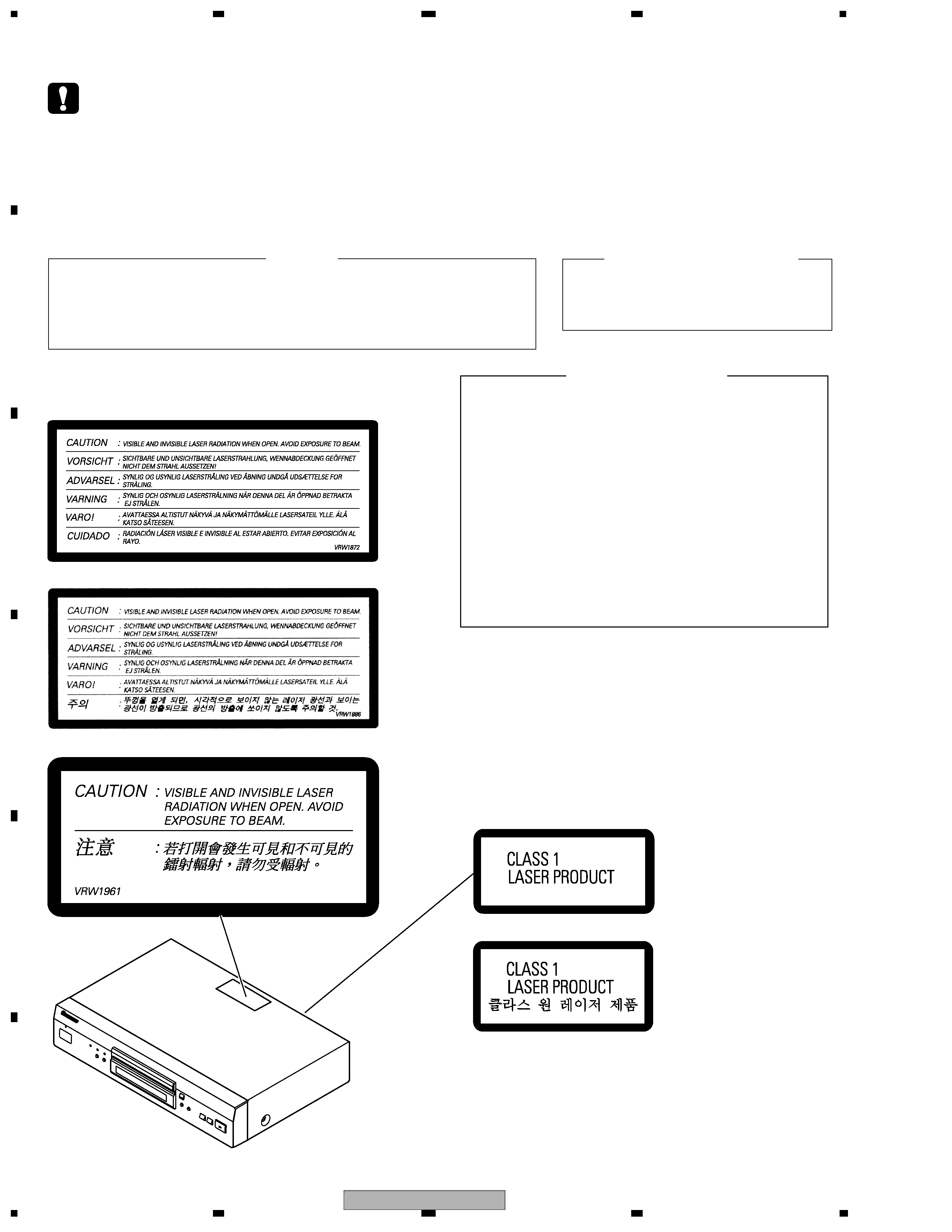
SAFETY INFORMATION
This service manual is intended for qualified service technicians ; it is not meant for the casual do-
it-yourselfer. Qualified technicians have the necessary test equipment and tools, and have been
trainedto properly and safely repair complex products such as those covered by this
manual.Improperly performed repairs can adversely affect the safety and reliability of the product
and mayvoid the warranty. If you are not qualified to perform the repair of this product properly and
safely, youshould not risk trying to do so and refer the repair to a qualified service technician.
WARNING !
THE AEL (ACCESSIBLE EMISSION LEVEL) OF THE LASER POWER OUTPUT IS LESS THAN
CLASS 1 BUT THE LASER COMPONENT IS CAPABLE OF EMITTING RADIATION EXCEEDING
THE LIMIT FOR CLASS 1.
A SPECIALLY INSTRUCTED PERSON SHOULD DO SERVICING OPERATION OF THE
APPARATUS.
LASER DIODE CHARACTERISTICS
FOR DVD : MAXIMUM OUTPUT POWER : 5 mW
WAVELENGTH : 650 nm
FOR CD :
MAXIMUM OUTPUT POWER : 5 mW
WAVELENGTH : 780 nm
LABEL CHECK
(Printed on the Rear Panel)
[RPW type]
[BK type]
[RLF type]
[RLF and RPW types]
[BK type]
Additional Laser Caution
: See page 67.
1. Loading-status detection switch (S101 on the LOAB assy) are detected
by the microprocessor (IC601 in the DVDM assy).
· To permit the laser diode to oscillate, it is required to set the loading-
status detection switch for the clamp position (the center terminal of
S101 is shorted to +3V).
When the voltage of IC101-pin 21 is +3V, IC601 (microprocessor)
-pin 83 is +3V and IC601-pin 84 is +3V, 650nm laser diode for DVD
oscillates in the DVDM Assy.
When the voltage of IC101-pin 21 is +3V, IC601 (microprocessor)
-pin 83 is 0V (GND) and IC601-pin 84 is +3V, 780nm laser diode for
CD oscillates in the DVDM Assy.
In the test mode * , the laser diode oscillates when microprocessor
detects a PLAY signal, or when the PLAY key is pressed (S104 ON in
the FLKY assy), with the above requirements satisfied.
2. When the cover is open, close viewing through the objective lens with
the naked eye will cause exposure to the laser beam.
DV-S969AVi
3
5
678
56
7
8
C
D
F
A
B
E
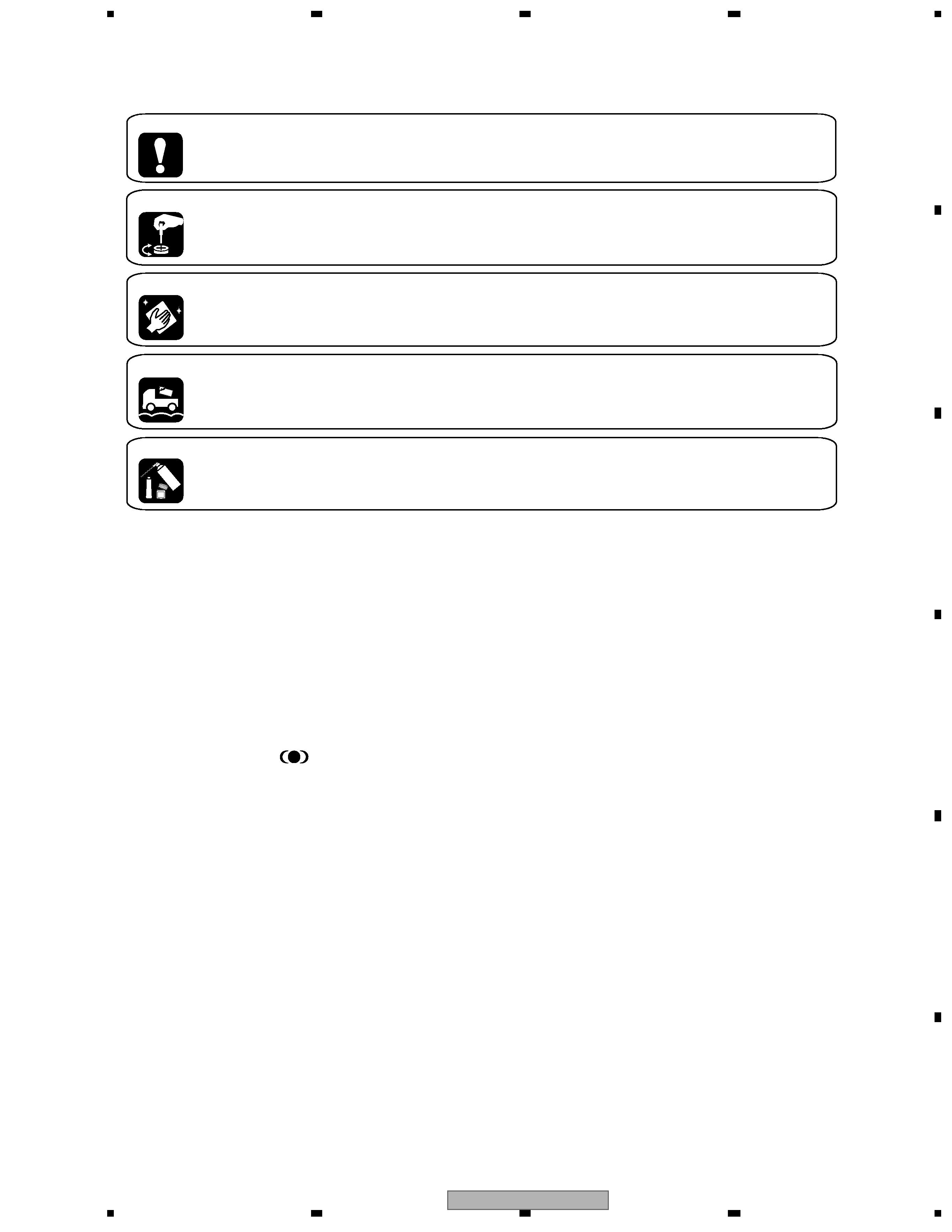
[ Important symbols for good services ]
In this manual, the symbols shown-below indicate that adjustments, settings or cleaning should be made securely.
When you find the procedures bearing any of the symbols, be sure to fulfill them:
2. Adjustments
To keep the original performances of the product, optimum adjustments or specification confirmation is indispensable.
In accordance with the procedures or instructions described in this manual, adjustments should be performed.
3. Cleaning
For optical pickups, tape-deck heads, lenses and mirrors used in projection monitors, and other parts requiring cleaning,
proper cleaning should be performed to restore their performances.
5. Lubricants, glues, and replacement parts
Appropriately applying grease or glue can maintain the product performances. But improper lubrication or applying
glue may lead to failures or troubles in the product. By following the instructions in this manual, be sure to apply the
prescribed grease or glue to proper portions by the appropriate amount.For replacement parts or tools, the prescribed
ones should be used.
4. Shipping mode and shipping screws
To protect the product from damages or failures that may be caused during transit, the shipping mode should be set or
the shipping screws should be installed before shipping out in accordance with this manual, if necessary.
1. Product safety
You should conform to the regulations governing the product (safety, radio and noise, and other regulations), and
should keep the safety during servicing by following the safety instructions described in this manual.
· Manufactured under license from Dolby
Laboratories. "Dolby" and the double-D symbol
are trademarks of Dolby Laboratories.
· "DTS" and "DTS Digital Out" are registered
trademarks of Digital Theater Systems, Inc.
· TruSurround and the
symbol are
trademarks of SRS Labs, Inc. TruSurround tech-
nology is incorporated under license from SRS
Labs, Inc.

DV-S969AVi
4
1234
123
4
C
D
F
A
B
E
CONTENTS
SAFETY INFORMATION ..................................................................................................................................... 2
1. SPECIFICATIONS ............................................................................................................................................ 5
2. EXPLODED VIEWS AND PARTS LIST ............................................................................................................ 6
2.1 PACKING ................................................................................................................................................... 6
2.2 EXTERIOR SECTION................................................................................................................................ 8
2.3 FRONT PANEL SECTION ....................................................................................................................... 10
2.4 LOADING MECHA. ASSY ....................................................................................................................... 12
2.5 TRAVERSE MECHA. ASSY-S ................................................................................................................. 14
3. BLOCK DIAGRAM AND SCHEMATIC DIAGRAM ..........................................................................................16
3.1 BLOCK DIAGRAM ................................................................................................................................... 16
3.1.1 BLOCK DIAGRAM 1/3 .......................................................................................................................... 16
3.1.2 BLOCK DIAGRAM 2/3 .......................................................................................................................... 18
3.1.3 BLOCK DIAGRAM 3/3 [POWER BLOCK]............................................................................................. 20
3.2 LOAB ASSY and OVERALL WIRING DIAGRAM..................................................................................... 22
3.3 DVDM ASSY 1/6 [FTS BLOCK] ............................................................................................................... 24
3.4 DVDM ASSY 2/6 [FR BLOCK] ................................................................................................................. 26
3.5 DVDM ASSY 3/6 [EBY/AV1 BLOCK] ....................................................................................................... 28
3.6 DVDM ASSY 4/6 [i.LINK BLOCK] ............................................................................................................ 30
3.7 DVDM ASSY 5/6 [VIDEO BLOCK]........................................................................................................... 32
3.8 DVDM ASSY 6/6 [A-DSP/AQE/SACD BLOCK]........................................................................................34
3.9 AJKB ASSY ............................................................................................................................................. 36
3.10 VJKB ASSY............................................................................................................................................ 38
3.11 FLKY, KEYB and MSWB ASSYS........................................................................................................... 40
3.12 POWER SUPPLY UNIT.......................................................................................................................... 42
3.13 WAVEFORMS ........................................................................................................................................ 44
4. PCB CONNECTION DIAGRAM ..................................................................................................................... 47
4.1 LOAB ASSY ............................................................................................................................................. 47
4.2 DVDM ASSY ............................................................................................................................................ 48
4.3 AJKB ASSY ............................................................................................................................................. 52
4.4 VJKB ASSY.............................................................................................................................................. 54
4.5 FLKY and KEYB ASSYS ......................................................................................................................... 56
4.6 MSWB ASSY ........................................................................................................................................... 58
4.7 POWER SUPPLY UNIT............................................................................................................................ 59
5. PCB PARTS LIST ........................................................................................................................................... 60
6. ADJUSTMENT ............................................................................................................................................... 65
6.1 ADJUSTMENT ITEMS AND LOCATION ................................................................................................. 65
6.2 JIGS AND MEASURING INSTRUMENTS ............................................................................................... 65
6.3 NECESSARY ADJUSTMENT POINTS ................................................................................................... 66
6.4 TEST MODE ............................................................................................................................................ 67
6.5 MECHANISM ADJUSTMENT .................................................................................................................. 68
7. GENERAL INFORMATION ............................................................................................................................. 70
7.1 DIAGNOSIS ............................................................................................................................................. 70
7.1.1 ID NUMBER AND ID DATA SETTING................................................................................................... 70
7.1.2 SELF-DIAGNOSIS FUNCTION OF PICKUP DEFECTIVE................................................................... 72
7.1.3 TEST MODE SCREEN DISPLAY ......................................................................................................... 73
7.1.4 SELF-DIAGNOSIS FUNCTION ............................................................................................................ 75
7.1.5 FUNCTIONAL SPECIFICATION OF THE SERVICE MODE................................................................. 76
7.1.6 ERROR DISPLAY ................................................................................................................................. 77
7.1.7 TROUBLE SHOOTING ......................................................................................................................... 80
7.1.8 FAILURE-TEST METHOD FOR THE HDMI TRANSMITTER IC .......................................................... 82
7.1.9 DISASSEMBLY ..................................................................................................................................... 83
7.2 IC ............................................................................................................................................................. 94
7.3 DISC / CONTENT FORMAT PLAYBACK COMPATIBILITY ................................................................... 146
7.4 CLEANING............................................................................................................................................. 147
8. PANEL FACILITIES ...................................................................................................................................... 148

DV-S969AVi
5
5
678
56
7
8
C
D
F
A
B
E
1. SPECIFICATIONS
Other types . . AC 110127/220240 V, 50/60Hz
DV-S969AVi . . . . . . . . . . . . . . . . . . . . . . . . 0.3 W
DV-S969AVi . . . . . . . . . . . . . . 5.6 kg (12 lb 6 oz)
DV-S969AVi . . 420 (W) x 109 (H) x 279 (D) mm
(16 9/16 (W) x 4 5/16 (H) x 11 (D) in.)
D1/D2 Video Output
(except BK and RPW types)
Output level . . . . . . . . . . . . . . . Y: 1.0 Vp-p (75
)
PB, PR: 0.7 Vp-p (75
)
Jacks. . . . . . . . . . . . . . . . . . . . . . D video terminal
BK type . . . . . . . . . . . . . . . . AC 110/220 V, 60Hz
DV-S969AVi
General
System . . . . . . . . . . . . . . . . . . . . . . . . DVD Player
Power requirements
Power consumption . . . . . . . . . . . . . . . . . . . 18 W
Power consumption (standby)
Weight
Dimensions
Operating temperature . . . . . . . +5
°C to +35°C
Operating humidity . . . . . . . . . . . . . . . 5% to 85%
(no condensation)
HDMI output
HDMI output . . . . . . . . . . . . . . . . . . . . . . . . 19 pin
i.LINK output
i.LINK output . . . . . . . . . . . . . . . . . . . 4 pin (S400)
Component Video output (Y, PB, PR)
Output level . . . . . . . . . . . . . . . Y: 1.0 Vp-p (75
)
PB, PR: 0.7 Vp-p (75
)
Jacks . . . . . . . . . . . . . . . . . . . . . . . . . . . RCA jacks
S-Video output
Y (luminance) - Output level . . . . . . 1 Vp-p (75
)
C (color) - Output level . . . . . . 286 mVp-p (75
)
Jack . . . . . . . . . . . . . . . . . . . . . . . . . . S-Video jack
Video output
Output level . . . . . . . . . . . . . . . . . . . 1 Vp-p (75 W)
Jack . . . . . . . . . . . . . . . . . . . . . . . . . . . . . RCA jack
Audio output (1 stereo pair)
Output level . . . . . . . . . . . . . During audio output
200 mVrms (1 kHz, 20 dB)
Number of channels . . . . . . . . . . . . . . . . . . . . . 2
Jacks . . . . . . . . . . . . . . . . . . . . . . . . . . . . RCA jack
Audio output (multi-channel / L, R, C,
SW, LS, RS)
Output level . . . . . . . . . . . . . During audio output
200 mVrms (1 kHz, 20 dB)
Number of channels . . . . . . . . . . . . . . . . . . . . . 6
Jacks . . . . . . . . . . . . . . . . . . . . . . . . . . . . RCA jack
Audio characteristics
Frequency response
. . . . . . . . . . . . . . 4 Hz to 44 kHz(DVD fs: 96 kHz)
. . . . . . . 4 Hz to 88 kHz (DVD-Audio fs: 192 kHz)
S/N ratio . . . . . . . . . . . . . . . . . . . . . . . . . . . 118dB
Dynamic range. . . . . . . . . . . . . . . . . . . . . 108.8dB
Total harmonic distortion. . . . . . . . . . . . 0.0008 %
Wow and flutter . . . . . . . . Limit of measurement
(0.001% W. PEAK) or lower
Digital output
Optical digital output. . . . . . . Optical digital jack
Coaxial digital output. . . . . . . . . . . . . . . RCA jack
Other terminals
Control in . . . . . . . . . . . . . . . . . . . Minijack (3.5 ø)
Control out . . . . . . . . . . . . . . . . . . Minijack (3.5 ø)
Accessories
Stereo audio cable . . . . . . . . . . . . . . . . . . . . . . . 1
Video cable . . . . . . . . . . . . . . . . . . . . . . . . . . . . . 1
4-pin S400 i.LINK cable . . . . . . . . . . . . . . . . . . . 1
Power cable . . . . . . . . . . . . . . . . . . . . . . . . . . . . . 1
Remote control . . . . . . . . . . . . . . . . . . . . . . . . . . 1
AA/R6P dry cell batteries
. . . . . . . . . . . . . . . . . 2
These operating instructions . . . . . . . . . . . . . . 1
Warranty card . . . . . . . . . . . . . . . . . . . . . . . . . . . 1
· The specifications and design of this
product are subject to change without
notice, due to improvement.