ORDER NO.
PIONEER CORPORATION 4-1, Meguro 1-chome, Meguro-ku, Tokyo 153-8654, Japan
PIONEER ELECTRONICS (USA) INC. P.O. Box 1760, Long Beach, CA 90801-1760, U.S.A.
PIONEER EUROPE NV Haven 1087, Keetberglaan 1, 9120 Melsele, Belgium
PIONEER ELECTRONICS ASIACENTRE PTE. LTD. 253 Alexandra Road, #04-01, Singapore 159936
PIONEER CORPORATION 2002
DV-757Ai
RRV2668
DVD PLAYER
DV-757Ai
DV-S755Ai
THIS MANUAL IS APPLICABLE TO THE FOLLOWING MODEL(S) AND TYPE(S).
Model
Type
Power Requirement
Regional restriction
codes (Region No.)
Remarks
DV-757Ai
WYXJ
AC220-240V
2
DV-S755Ai
RLXJ/NC
AC110-127V/220-240V
3
For details, refer to "Important symbols for good services".
T-ZZE SEPT. 2002 printed in Japan
DV-757Ai
2
1234
123
4
C
D
F
A
B
E
SAFETY INFORMATION
This service manual is intended for qualified service technicians; it is not meant for the casual
do-it-yourselfer. Qualified technicians have the necessary test equipment and tools, and have been
trainedto properly and safely repair complex products such as those covered by this manual.
Improperly performed repairs can adversely affect the safety and reliability of the product and
may void the warranty. If you are not qualified to perform the repair of this product properly and
safely, you should not risk trying to do so and refer the repair to a qualified service technician.
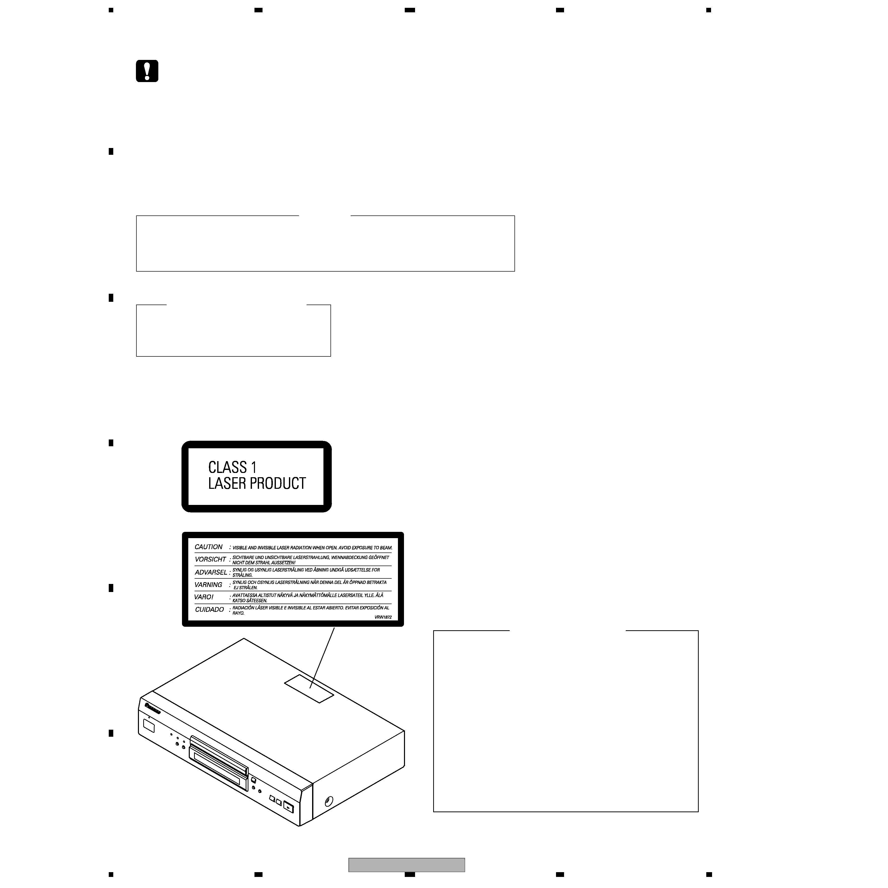
WARNING !
THE AEL (ACCESSIBLE EMISSION LEVEL) OF THE LASER POWER OUTPUT IS LESS THAN CLASS 1
BUT THE LASER COMPONENT IS CAPABLE OF EMITTING RADIATION EXCEEDING THE LIMIT FOR
CLASS 1.
A SPECIALLY INSTRUCTED PERSON SHOULD DO SERVICING OPERATION OF THE APPARATUS.
LASER DIODE CHARACTERISTICS
FOR DVD : MAXIMUM OUTPUT POWER : 5 mW
WAVELENGTH : 650 nm
FOR CD :
MAXIMUM OUTPUT POWER : 5 mW
WAVELENGTH : 780 nm
Additional Laser Caution
: See page 70.
LABEL CHECK
1. Loading-status detection switch (S101 on the LOAB assy) are detected
by the microprocessor (IC601 in the DVDM assy).
· To permit the laser diode to oscillate, it is required to set the loading-
status detection switch for the clamp position (the center terminal of
S101 is shorted to +3V).
When the voltage of IC101-pin 20 is +3V, IC601 (microprocessor)
-pin 83 is +3V and IC601-pin 84 is +3V, 650nm laser diode for DVD
oscillates in the DVDM Assy.
When the voltage of IC101-pin 20 is +3V, IC601 (microprocessor)
-pin 83 is 0V (GND) and IC601-pin 84 is +3V, 780nm laser diode for
CD oscillates in the DVDM Assy.
In the test mode * , the laser diode oscillates when microprocessor
detects a PLAY signal, or when the PLAY key is pressed (S104 ON in
the FLKY assy), with the above requirements satisfied.
2. When the cover is open, close viewing through the objective lens with
the naked eye will cause exposure to the laser beam.
Location: Printed on the Rear Panel
DV-757Ai
3
5
678
56
7
8
C
D
F
A
B
E
[ Important symbols for good services ]
In this manual, the symbols shown-below indicate that adjustments, settings or cleaning should be made securely.
When you find the procedures bearing any of the symbols, be sure to fulfill them:
2. Adjustments
To keep the original performances of the product, optimum adjustments or specification confirmation is indispensable.
In accordance with the procedures or instructions described in this manual, adjustments should be performed.
3. Cleaning
For optical pickups, tape-deck heads, lenses and mirrors used in projection monitors, and other parts requiring cleaning,
proper cleaning should be performed to restore their performances.
5. Lubricants, glues, and replacement parts
Appropriately applying grease or glue can maintain the product performances. But improper lubrication or applying
glue may lead to failures or troubles in the product. By following the instructions in this manual, be sure to apply the
prescribed grease or glue to proper portions by the appropriate amount.For replacement parts or tools, the prescribed
ones should be used.
4. Shipping mode and shipping screws
To protect the product from damages or failures that may be caused during transit, the shipping mode should be set or
the shipping screws should be installed before shipping out in accordance with this manual, if necessary.
1. Product safety
You should conform to the regulations governing the product (safety, radio and noise, and other regulations), and
should keep the safety during servicing by following the safety instructions described in this manual.

DV-757Ai
4
1234
123
4
C
D
F
A
B
E
CONTENTS
SAFETY INFORMATION ..................................................................................................................................... 2
1. SPECIFICATIONS ............................................................................................................................................ 5
2. EXPLODED VIEWS AND PARTS LIST ............................................................................................................ 8
2.1 PACKING ................................................................................................................................................... 8
2.2 EXTERIOR SECTION.............................................................................................................................. 10
2.3 FRONT PANEL SECTION ....................................................................................................................... 12
2.4 LOADING MECHA ASSY ........................................................................................................................ 14
2.5 TRAVERSE MECHANISM ASSY-S ......................................................................................................... 16
3. BLOCK DIAGRAM AND SCHEMATIC DIAGRAM ..........................................................................................18
3.1 BLOCK DIAGRAM ................................................................................................................................... 18
3.2 LOAB ASSY and OVERALL WIRING DIAGRAM..................................................................................... 22
3.3 DVDM ASSY 1/4 [FTS BLOCK] ............................................................................................................... 24
3.4 DVDM ASSY 2/4 [FR BLOCK] ................................................................................................................. 26
3.5 DVDM ASSY 3/4 [EBY/AV1 BLOCK] ....................................................................................................... 28
3.6 DVDM ASSY 4/4 [VENC BLOCK] ............................................................................................................ 30
3.7 JACB ASSY 1/2 [AUDIO BLOCK] ............................................................................................................ 32
3.8 JACB ASSY 2/2 [VIDEO BLOCK] ............................................................................................................ 34
3.9 SACDB ASSY .......................................................................................................................................... 36
3.10 FLKY, KEYB and MSWB ASSYS........................................................................................................... 38
3.11 SCRB ASSY [WYXJ Type Only]............................................................................................................. 40
3.12 ILKB ASSY............................................................................................................................................. 42
3.13 POWER SUPPLY UNIT.......................................................................................................................... 44
3.14 WAVEFORMS [DVDM ASSY] ................................................................................................................ 45
3.15 WAVEFORMS [JACB ASSY] ................................................................................................................. 46
4. PCB CONNECTION DIAGRAM ..................................................................................................................... 47
4.1 LOAB ASSY ............................................................................................................................................. 47
4.2 DVDM ASSY ............................................................................................................................................ 48
4.3 JACB ASSY ............................................................................................................................................. 50
4.4 SACDB ASSY .......................................................................................................................................... 54
4.5 SCRB ASSY ............................................................................................................................................ 55
4.6 FLKY and KEYB ASSYS ......................................................................................................................... 56
4.7 POWER SUPPLY UNIT............................................................................................................................ 58
4.8 ILKB ASSY............................................................................................................................................... 59
4.9 MSWB ASSY ........................................................................................................................................... 60
5. PCB PARTS LIST ........................................................................................................................................... 61
6. ADJUSTMENT ............................................................................................................................................... 68
6.1 ADJUSTMENT ITEMS AND LOCATION ................................................................................................. 68
6.2 JIGS AND MEASURING INSTRUMENTS ............................................................................................... 68
6.3 NECESSARY ADJUSTMENT POINTS ................................................................................................... 69
6.4 TEST MODE ............................................................................................................................................ 70
6.5 MECHANISM ADJUSTMENT .................................................................................................................. 71
7. GENERAL INFORMATION ............................................................................................................................. 74
7.1 DIAGNOSIS ............................................................................................................................................. 74
7.1.1 ID NUMBER AND ID DATA SETTTING ................................................................................................ 74
7.1.2 SELF-DIAGNOSIS FUNCTION OF PICKUP DEFECTIVE................................................................... 76
7.1.3 TEST MODE SCREEN DISPLAY ......................................................................................................... 77
7.1.4 SELF-DIAGNOSIS FUNCTION ............................................................................................................ 79
7.1.5 FUNCTION SPECIFICATION OF THE SERVICE MODE ..................................................................... 80
7.1.6 ERROR DISPLAY ................................................................................................................................. 81
7.1.7 TEST POINTS LOCATION & WAVEFORMS ........................................................................................ 84
7.1.8 TROUBLE SHOOTING ......................................................................................................................... 86
7.1.9 DISASSEMBLY ..................................................................................................................................... 88
7.2 IC ............................................................................................................................................................. 97
7.3 DISC / CONTENT FORMAT PLAYBACK COMPATIBILITY ................................................................... 152
7.4 CLEANING............................................................................................................................................. 153
8. PANEL FACILITIES ...................................................................................................................................... 154
DV-757Ai
5
5
678
56
7
8
C
D
F
A
B
E
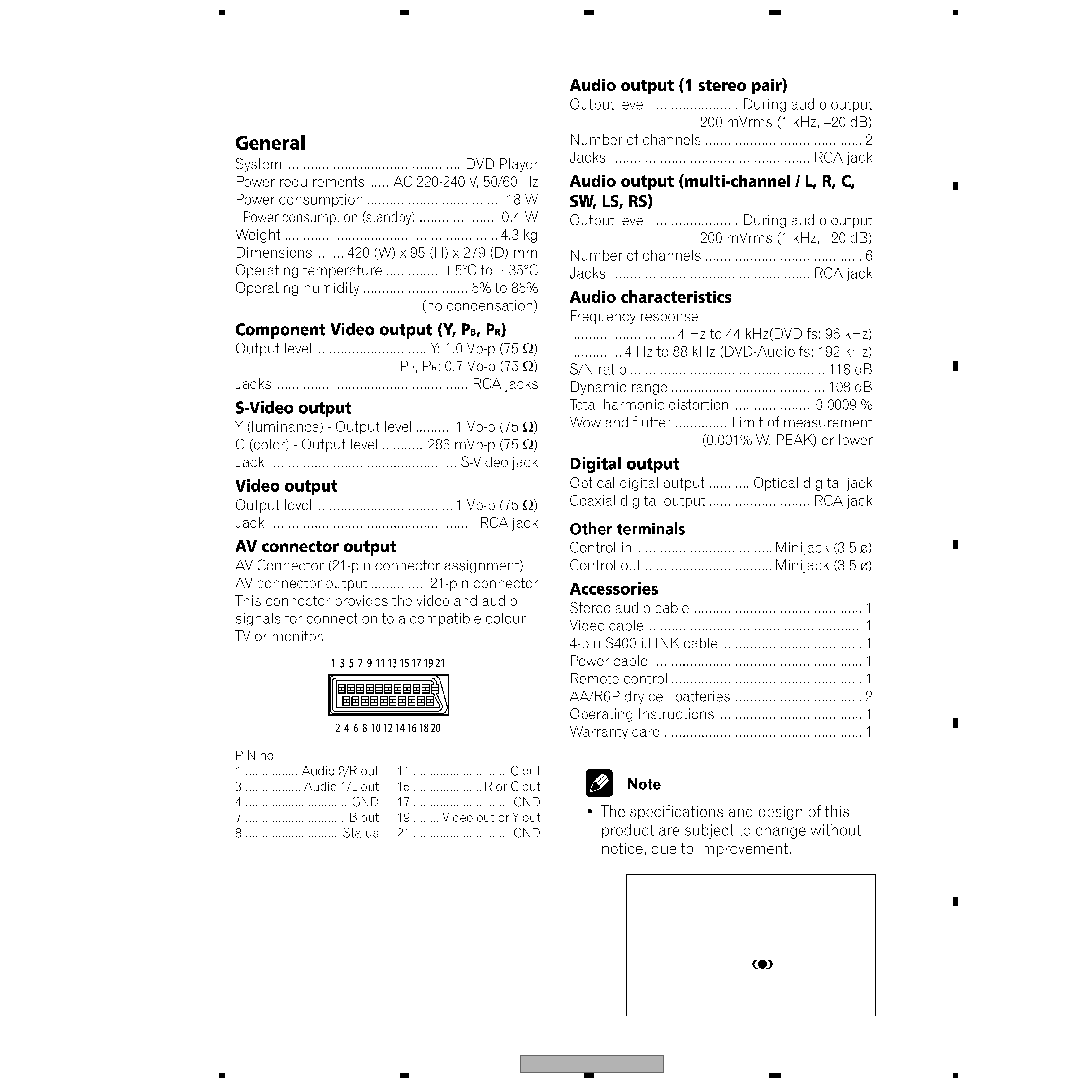
1. SPECIFICATIONS
· Manufactured under license from Dolby
Laboratories. "Dolby" and the double-D
symbol are trademarks of Dolby Laboratories.
· "DTS" is a registered trademark of Digital
Theater Systems, Inc.
· TruSurround and the
® symbol are
trademarks of SRS Labs, Inc. TruSurround
technology is incorporated under license from
SRS Labs, Inc.
7 DV-757Ai/WYXJ