ORDER NO.
PIONEER CORPORATION 4-1, Meguro 1-chome, Meguro-ku, Tokyo 153-8654, Japan
PIONEER ELECTRONICS SERVICE, INC. P.O. Box 1760, Long Beach, CA 90801-1760, U.S.A.
PIONEER ELECTRONIC (EUROPE) N.V. Haven 1087, Keetberglaan 1, 9120 Melsele, Belgium
PIONEER ELECTRONICS ASIACENTRE PTE. LTD. 253 Alexandra Road, #04-01, Singapore 159936
PIONEER CORPORATION 1999
c
DV-S6D
RRV2228
1. SAFETY INFORMATION ....................................... 2
2. EXPLODED VIEWS AND PARTS LIST ................. 3
3. BLOCK DIAGRAM AND SCHEMATIC DIAGRAM .. 10
4. PCB CONNECTION DIAGRAM ........................... 33
5. PCB PARTS LIST ................................................ 46
6. ADJUSTMENT ..................................................... 51
CONTENTS
7. GENERAL INFORMATION .................................. 53
7.1 DIAGNOSIS ................................................... 53
7.1.1 TEST MODE SCREEN DISPLAY ............. 53
7.1.2 TROUBLE SHOOTING ............................ 55
7.1.3 ERROR CODE ......................................... 56
7.1.4 DISASSEMBLY ........................................ 60
7.2 PARTS ........................................................... 61
7.2.1 IC ............................................................. 61
7.2.2 DISPLAY .................................................. 78
8. PANEL FACILITIES AND SPECIFICATIONS ....... 79
T ZZE OCT. 1999 Printed in Japan
DVD PLAYER
Type
Model
Power Requirement
Region No.
Remarks
DV-S6D
LB
AC110V
3
THIS MANUAL IS APPLICABLE TO THE FOLLOWING MODEL(S) AND TYPE(S).
DVD PLAYER
STANDBY / ON
STANDBY
DNR
FL OFF
ACOUSTIC DAMPER MECHANISM
5.1CH
MODE
ÛN¿>Û
Î
0
4¢
1¡
7
3~8
2
DV-S6D
1. SAFETY INFORMATION
This service manual is intended for qualified service technicians ; it is not meant for the casual do-it-
yourselfer. Qualified technicians have the necessary test equipment and tools, and have been trained
to properly and safely repair complex products such as those covered by this manual.
Improperly performed repairs can adversely affect the safety and reliability of the product and may
void the warranty. If you are not qualified to perform the repair of this product properly and safely, you
should not risk trying to do so and refer the repair to a qualified service technician.
WARNING
This product contains lead in solder and certain electrical parts contain chemicals which are known to the state of California to cause
cancer, birth defects or other reproductive harm.
Health & Safety Code Section 25249.6 Proposition 65
NOTICE
(FOR CANADIAN MODEL ONLY)
Fuse symbols
(fast operating fuse) and/or
(slow operating fuse) on PCB indicate that replacement parts must
be of identical designation.
REMARQUE
(POUR MODÈLE CANADIEN SEULEMENT)
Les symboles de fusible
(fusible de type rapide) et/ou
(fusible de type lent) sur CCI indiquent que les pièces
de remplacement doivent avoir la même désignation.
ANY MEASUREMENTS NOT WITHIN THE LIMITS
OUTLINED ABOVE ARE INDICATIVE OF A POTENTIAL
SHOCK HAZARD AND MUST BE CORRECTED BEFORE
RETURNING THE APPLIANCE TO THE CUSTOMER.
2. PRODUCT SAFETY NOTICE
Many electrical and mechanical parts in the appliance
have special safety related characteristics. These are
often not evident from visual inspection nor the protection
afforded by them necessarily can be obtained by using
replacement components rated for voltage, wattage, etc.
Replacement parts which have these special safety
characteristics are identified in this Service Manual.
Electrical components having such features are identified
by marking with a
on the schematics and on the parts list
in this Service Manual.
The use of a substitute replacement component which does
not have the same safety characteristics as the PIONEER
recommended replacement one, shown in the parts list in
this Service Manual, may create shock, fire, or other hazards.
Product Safety is continuously under review and new
instructions are issued from time to time. For the latest
information, always consult the current PIONEER Service
Manual. A subscription to, or additional copies of, PIONEER
Service Manual may be obtained at a nominal charge from
PIONEER.
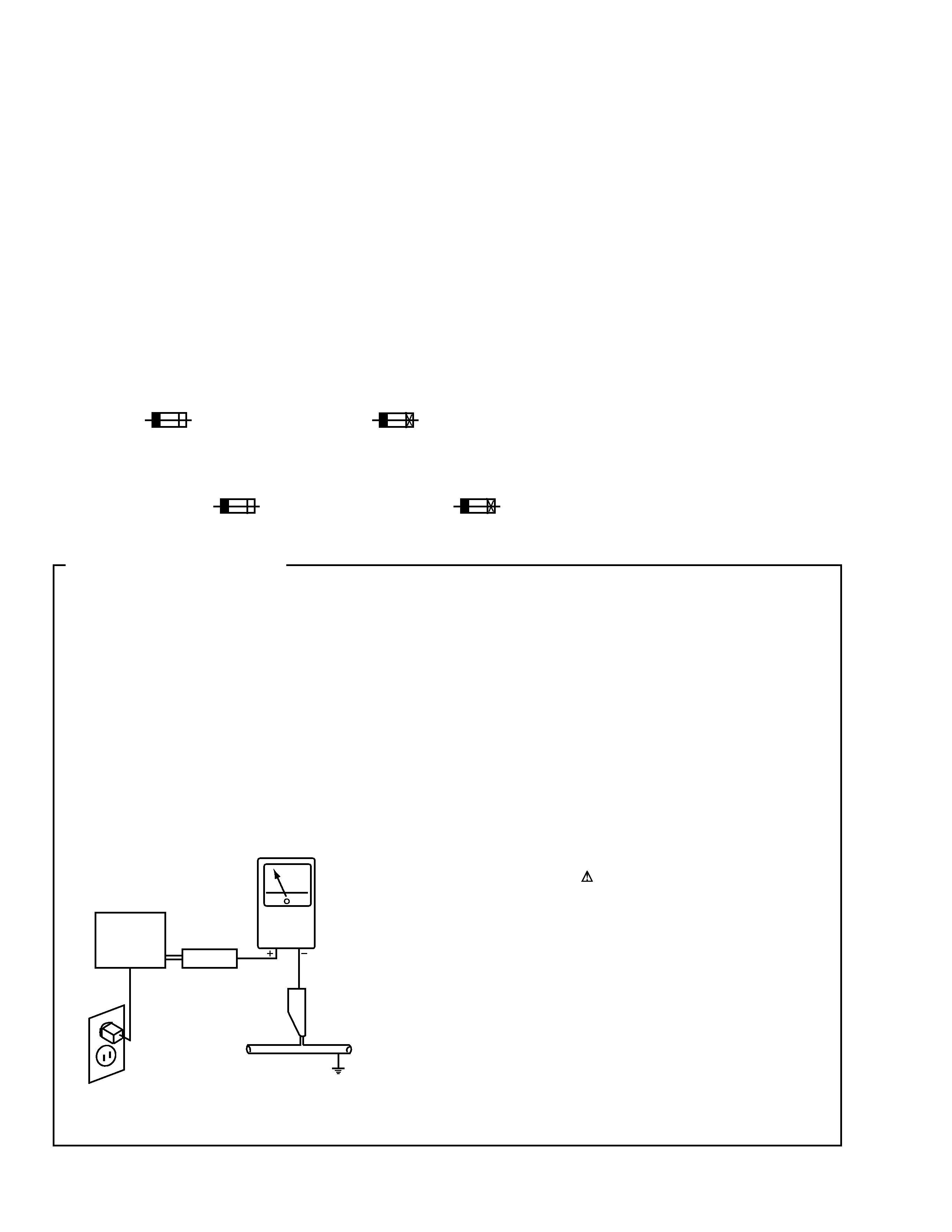
1. SAFETY PRECAUTIONS
The following check should be performed for the
continued protection of the customer and service
technician.
LEAKAGE CURRENT CHECK
Measure leakage current to a known earth ground (water
pipe, conduit, etc.) by connecting a leakage current tester
such as Simpson Model 229-2 or equivalent between the
earth ground and all exposed metal parts of the appliance
(input/output terminals, screwheads, metal overlays, control
shaft, etc.). Plug the AC line cord of the appliance directly
into a 120V AC 60Hz outlet and turn the AC power switch
on. Any current measured must not exceed 0.5mA.
(FOR USA MODEL ONLY)
Leakage
current
tester
Reading should
not be above
0.5mA
Device
under
test
Test all
exposed metal
surfaces
Also test with
plug reversed
(Using AC adapter
plug as required)
Earth
ground
AC Leakage Test
DV-S6D
3
1
Power Cord
ADG7006
2
· · · · ·
3
· · · · ·
4
· · · · ·
5
Audio Cord (L=1.5m)
VDE1033
6
Video Cord (L=1.5m)
VDE1034
NSP
7
Dry Cell Battery(R6P,AA)
VEM-013
8
Operating Instructions
VRD1091
(English/Trad-Chinese)
9
· · · · ·
10
Polyethylene Bag
VHL1051
(0.03
×200×300)
11
Protector A
VHB1065
12
Protector B
VHB1076
13
Packing Case
VHG1878
14
Mirror Mat Sheet
VHL1012
15
Remote Control Unit
VXX2628
(CU-DV037)
16
Battery Cover
VNK4422
10
8
11
14
10
12
16
15
1
6
5
13
7
Mark No.
Description
Part No.
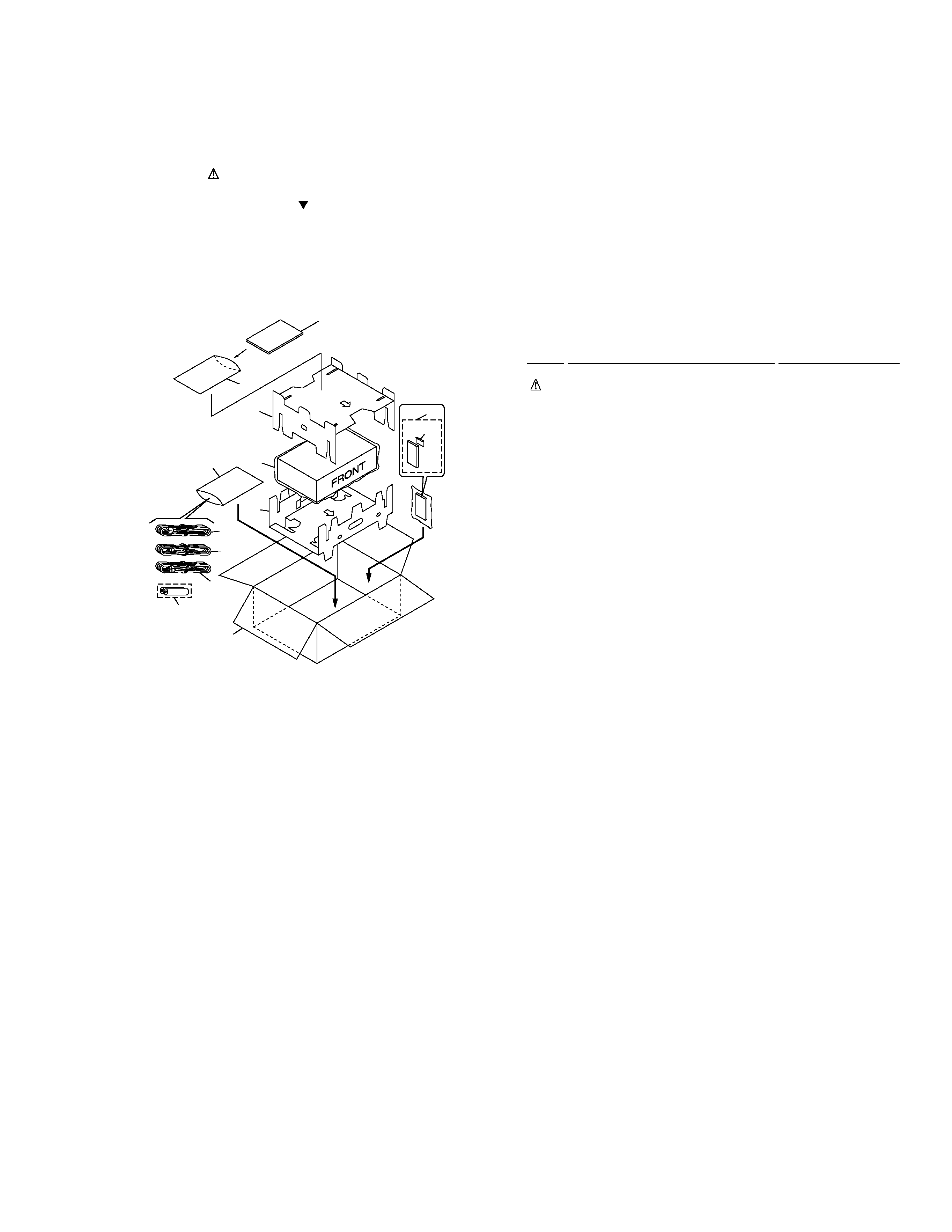
2.1 PACKING
2. EXPLODED VIEWS AND PARTS LIST
NOTES:
· Parts marked by "NSP" are generally unavailable because they are not in our Master Spare Parts List.
· The mark found on some component parts indicates the importance of the safety factor of the part.
Therefore, when replacing, be sure to use parts of identical designation.
· Screws adjacent to mark on the product are used for disassembly.
¶ PACKING PARTS LIST
DV-S6D
4
11
7
8
16
6
11
14
13
12
15
16
1
10
17
5
2
4
9
19
20
3
19
20
16
16
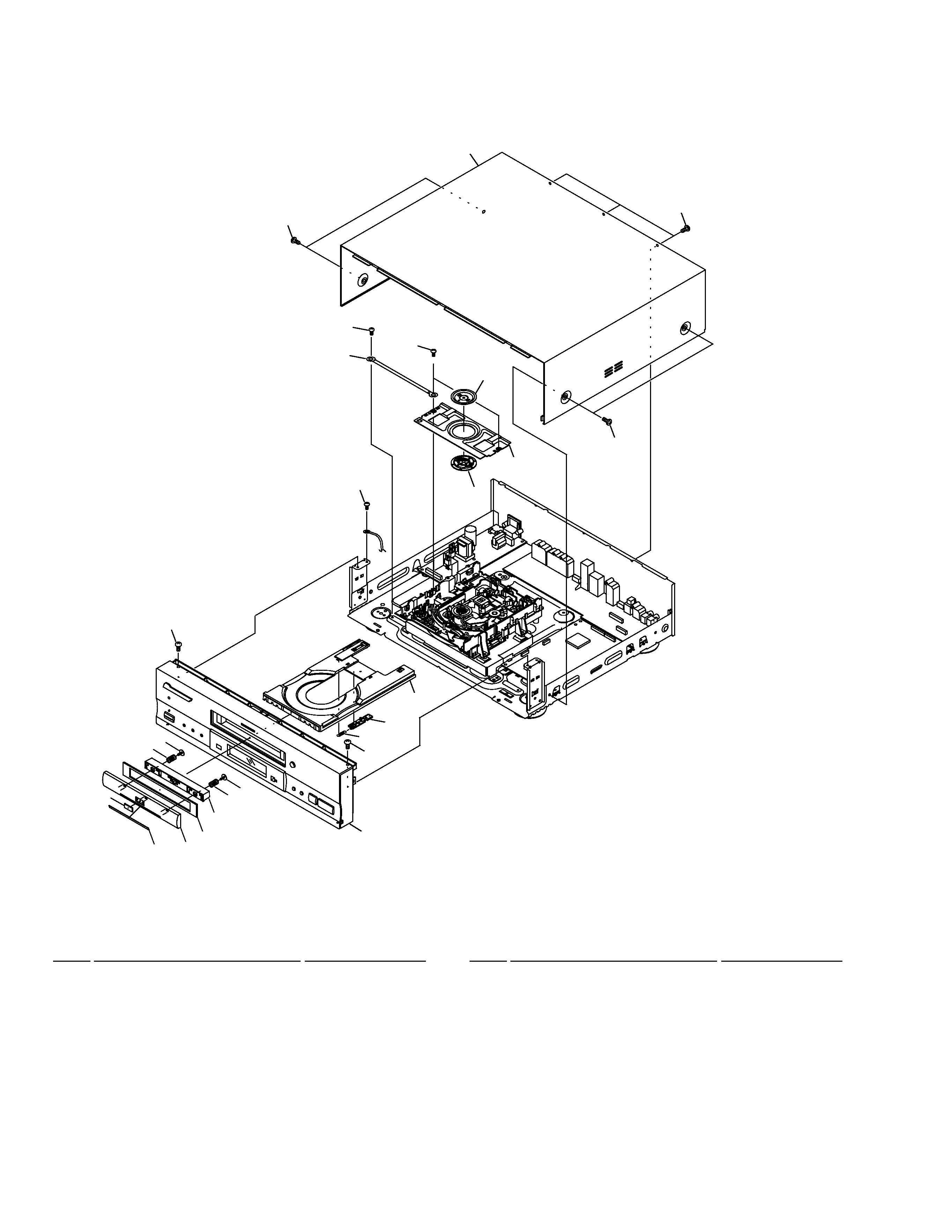
Refer to "2.3 FRONT PANEL SECTION".
1
Bonnet S
VXX2617
2
Door Panel
VNK4524
3
DVD Plate
VAM1077
4
Door Cushion
VEC2103
5
Door Plate
VEC2104
6
Tray
VNK4333
7
Tray Stopper
VNL1739
8
Tray Stopper Spring
VBH1277
9
Door Holder
VNK4325
10
Screw
IBZ30P060FCC
11
Screw
BCZ40P060FNI
12
Clamper Plate
VNE2068
13
Bridge
VNE2069
14
Clamper
VNL1738
15
Screw
BPZ26P080FZK
16
Screw
BBZ30P080FMC
NSP
17
Cord with Plug
DE010VF0
18
· · · · ·
19
Screw
VBA1057
20
Door Spring
VBH1305
Mark No.
Description
Part No.
Mark No.
Description
Part No.
2.2 EXTERIOR SECTION
¶ EXTERIOR SECTION PARTS LIST
DV-S6D
5
1
FLKY Assy
VWG2093
NSP
2
PWSB Assy
VWG2098
NSP
3
DILB Assy
VWG2100
4
Front Almi
VAH1328
5
Panel Base
VNK4323
6
FL Lens
VEC2089
7
Name Plate
PAN1377
8
PW Button (POWER)
VNK4059
9
Main Key
VNK4095
10
Screw
BBZ30P080FMC
Mark No.
Description
Part No.
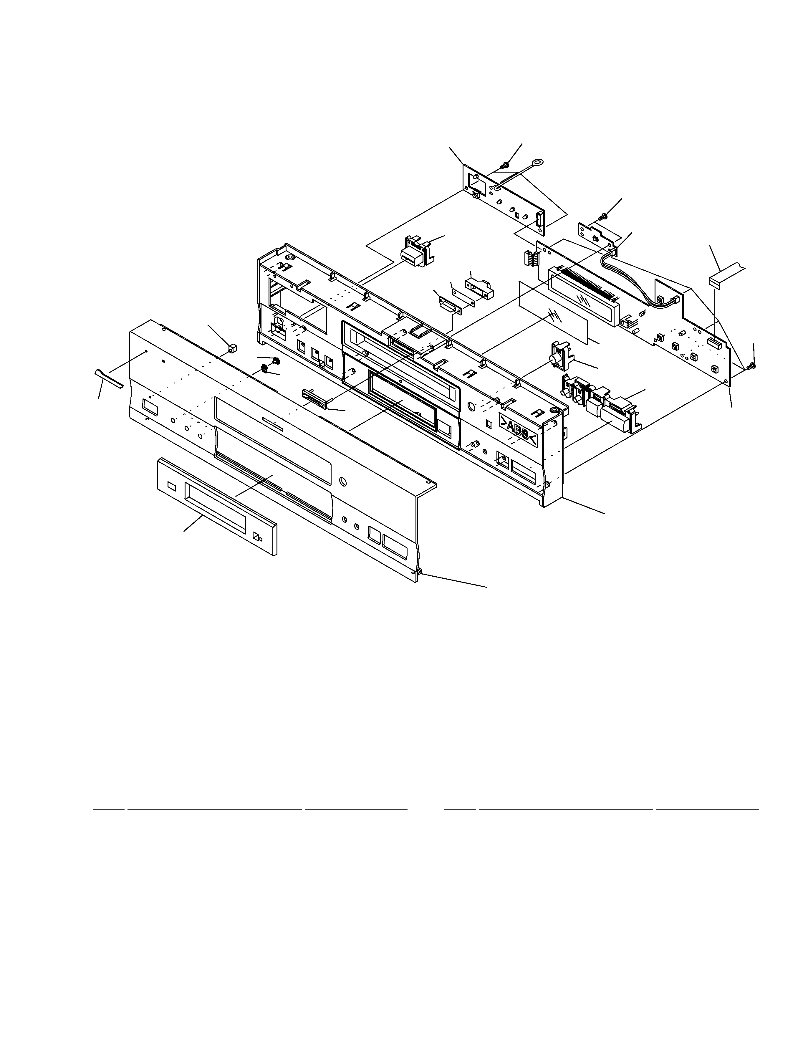
1
2
3
4
5(1/3)
5(3/3)
5(2/3)
6
7
11
15
8
12
13
14
9(1/2)
9(2/2)
10
10
16
17
10
Mark No.
Description
Part No.
11
LED Lens
PNW2019
12
Illumi Holder
VNK4098
13
Illumination Filter
VEC1950
14
Illumination Lens
VNK4168
15
LED Lens
VNK4326
16
Flexible Cable (15P)
VDA1728
(FLKY CN101
DVDM CN602)
17
FL Filter
VEC2016
¶ FRONT PANEL SECTION PARTS LIST
2.3 FRONT PANEL SECTION