ORDER NO.
PIONEER CORPORATION 4-1, Meguro 1-chome, Meguro-ku, Tokyo 153-8654, Japan
PIONEER ELECTRONICS (USA) INC. P.O. Box 1760, Long Beach, CA 90801-1760, U.S.A.
PIONEER EUROPE NV Haven 1087, Keetberglaan 1, 9120 Melsele, Belgium
PIONEER ELECTRONICS ASIACENTRE PTE. LTD. 253 Alexandra Road, #04-01, Singapore 159936
PIONEER CORPORATION 2005
OPEN/
CLOSE
COPY
SELECT
VHS AUTO
COPY
COPY
REC
PLAY
VHS/HDD/DVD
VHS
EJECT
INPUT2
STANDBY/ON
VIDEO
L (MONO)-AUDIO-R
HDD/DVD
S-VIDEO
VHS
HDD
DVD
START
DVR-RT601H-S
RRV3272
DVD RECORDER
DVR-RT601H-S
THIS MANUAL IS APPLICABLE TO THE FOLLOWING MODEL(S) AND TYPE(S).
Model
Type
Power Requirement
Region No.
Remarks
DVR-RT601H-S
YXGB5
AC220-240V
2
DVR-RT601H-S
VXGB5
AC220-240V
2
For details, refer to "Important Check Points for good servicing" .
T-ZZV SEPT. 2005 printed in Japan
DVR-RT601H-S
2
12
34
12
3
4
C
D
F
A
B
E
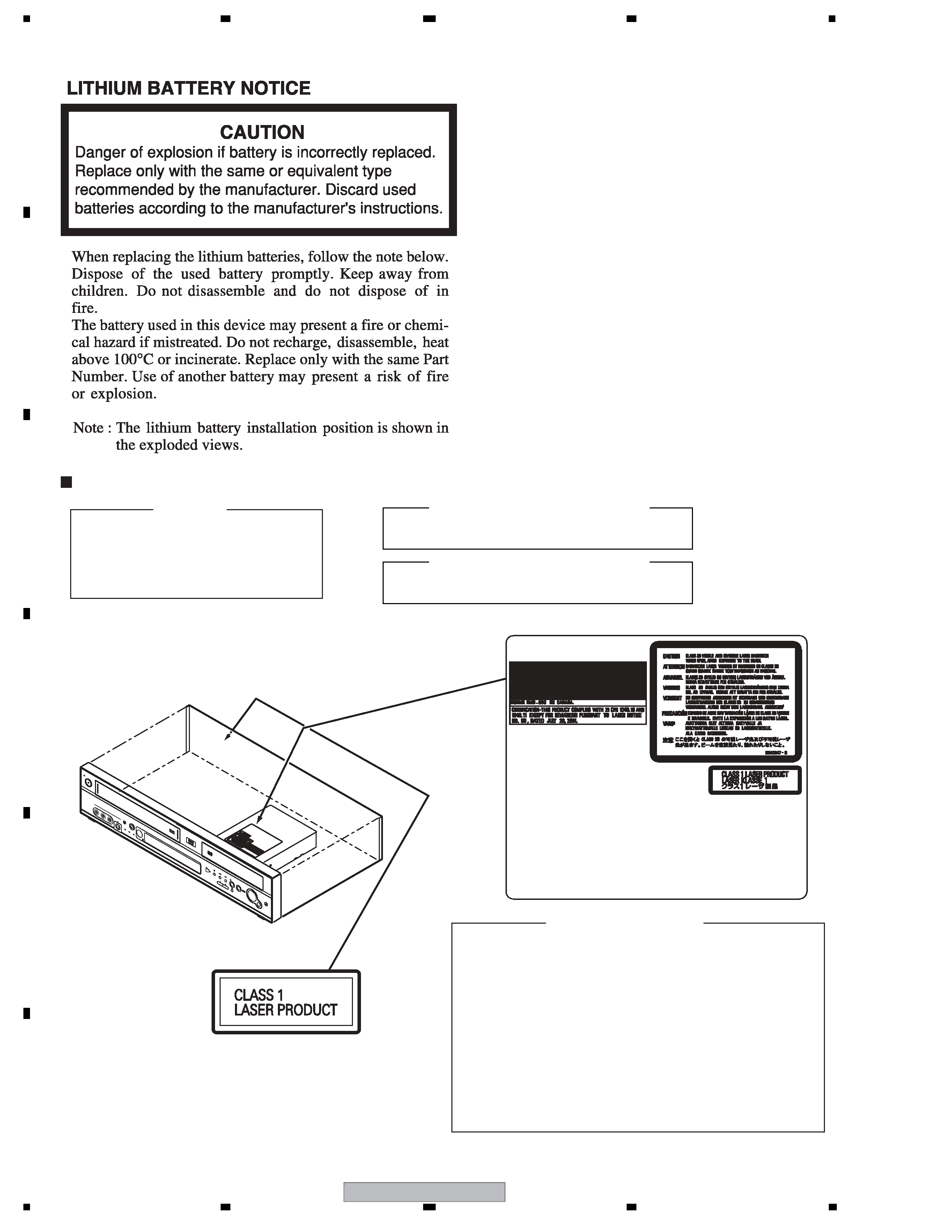
SAFETY INFORMATION
LABEL CHECK
IMPORTANT
THIS PIONEER APPARATUS CONTAINS
LASER OF CLASS 1.
SERVICING OPERATION OF THE APPARATUS
SHOULD BE DONE BY A SPECIALLY
INSTRUCTED PERSON.
CLAMP signals for detecting the loading state are detected
by the drive CPUs, and the design prevents laser diode
oscillation when the CLAMP signal turns OFF.
In normal operation, if no disc is clamped, the laser diode
oscillation is disabled.
However, the interlock does not always operate in the test
mode.
2. When the cover is opened, close viewing of the objective
lens with the naked eye will cause exposure to a Class 3A
laser beam.
Additional Laser Caution
1. The ON/OFF(ON:low level,OFF:high level) status of the
LASER DIODE CHARACTERISTICS
MAXIMUM OUTPUT POWER: 100 mW
WAVELENGTH: 654 - 662 nm
LASER DIODE CHARACTERISTICS
MAXIMUM OUTPUT POWER: 5 mW
WAVELENGTH: 770 - 810 nm
OP
EN
/
CL
OS
E
CO
PY
SE
LE
CT
VH
S
AU
TO
CO
PY
COPY
RE
C
PL
AY
VH
S/H
DD
/D
VD
VH
S
EJE
CT
INP
UT
2
ST
AN
DB
Y/O
N
VID
EO
L
(MONO)-
AU
DIO
-R
HD
D/D
VD
S-V
ID
EO
VH
S
HD
D
DV
D
ST
AR
T
DRW2247
(Printed on the Rear Panel)
DVR-RT601H-S
3
56
78
56
7
8
C
D
F
A
B
E
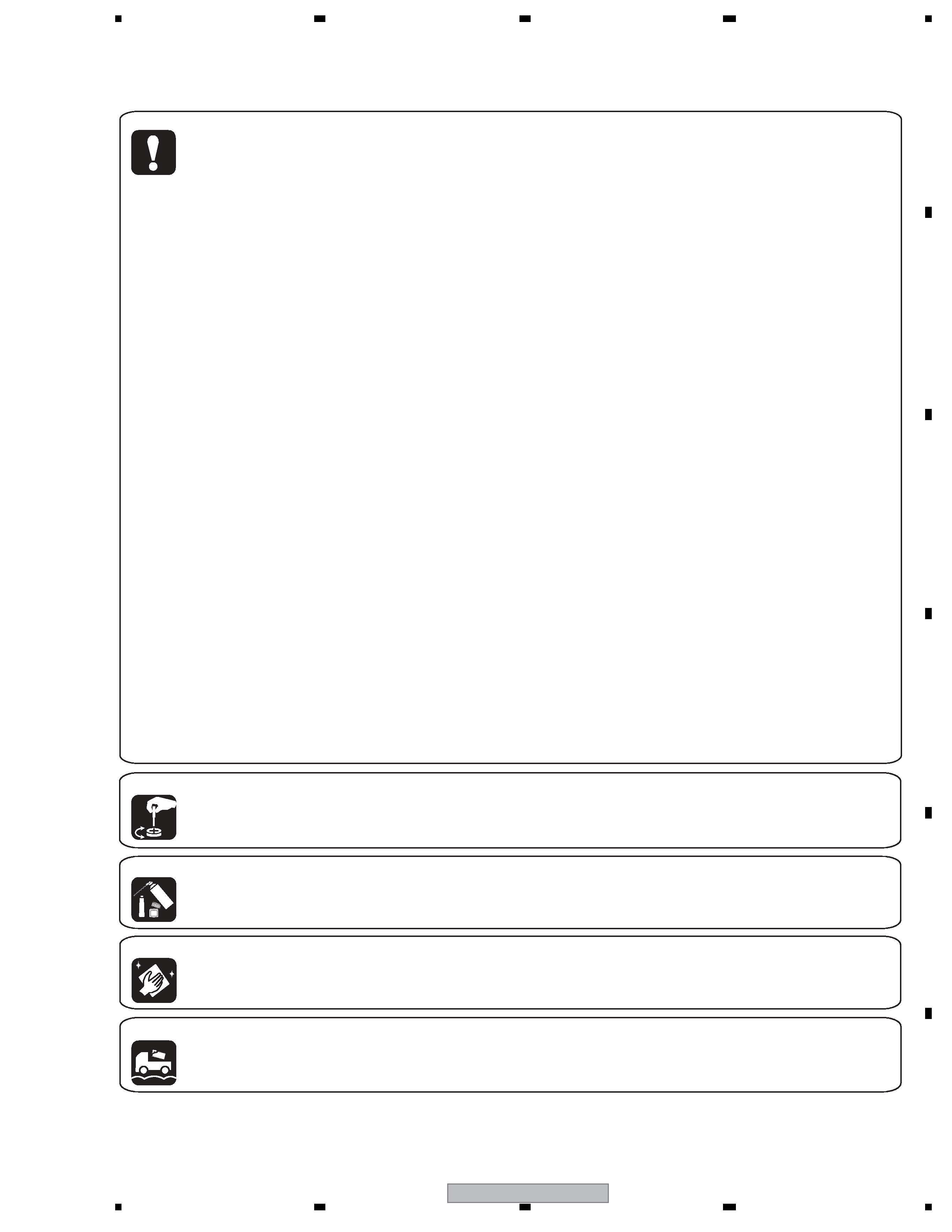
[Important Check Points for Good Servicing]
In this manual, procedures that must be performed during repairs are marked with the below symbol.
Please be sure to confirm and follow these procedures.
1. Product safety
Please conform to product regulations (such as safety and radiation regulations), and maintain a safe servicing environment by
following the safety instructions described in this manual.
1 Use specified parts for repair.
Use genuine parts. Be sure to use important parts for safety.
2 Do not perform modifications without proper instructions.
Please follow the specified safety methods when modification(addition/change of parts) is required due to interferences such as
radio/TV interference and foreign noise.
3 Make sure the soldering of repaired locations is properly performed.
When you solder while repairing, please be sure that there are no cold solder and other debris.
Soldering should be finished with the proper quantity. (Refer to the example)
4 Make sure the screws are tightly fastened.
Please be sure that all screws are fastened, and that there are no loose screws.
5 Make sure each connectors are correctly inserted.
Please be sure that all connectors are inserted, and that there are no imperfect insertion.
6 Make sure the wiring cables are set to their original state.
Please replace the wiring and cables to the original state after repairs.
In addition, be sure that there are no pinched wires, etc.
7 Make sure screws and soldering scraps do not remain inside the product.
Please check that neither solder debris nor screws remain inside the product.
8 There should be no semi-broken wires, scratches, melting, etc. on the coating of the power cord.
Damaged power cords may lead to fire accidents, so please be sure that there are no damages.
If you find a damaged power cord, please exchange it with a suitable one.
9 There should be no spark traces or similar marks on the power plug.
When spark traces or similar marks are found on the power supply plug, please check the connection and advise on secure
connections and suitable usage. Please exchange the power cord if necessary.
0 Safe environment should be secured during servicing.
When you perform repairs, please pay attention to static electricity, furniture, household articles, etc. in order to prevent injuries.
Please pay attention to your surroundings and repair safely.
2. Adjustments
To keep the original performance of the products, optimum adjustments and confirmation of characteristics within specification.
Adjustments should be performed in accordance with the procedures/instructions described in this manual.
4. Cleaning
For parts that require cleaning, such as optical pickups, tape deck heads, lenses and mirrors used in projection monitors, proper
cleaning should be performed to restore their performances.
3. Lubricants, Glues, and Replacement parts
Use grease and adhesives that are equal to the specified substance.
Make sure the proper amount is applied.
5. Shipping mode and Shipping screws
To protect products from damages or failures during transit, the shipping mode should be set or the shipping screws should be
installed before shipment. Please be sure to follow this method especially if it is specified in this manual.

DVR-RT601H-S
4
12
34
12
3
4
C
D
F
A
B
E
CONTENTS
SAFETY INFORMATION ..................................................................................................................................... 2
1. SPECIFICATIONS ............................................................................................................................................ 6
2. EXPLODED VIEWS AND PARTS LIST .......................................................................................................... 10
2.1 PACKING ................................................................................................................................................. 10
2.2 EXTERIOR SECTION.............................................................................................................................. 12
2.4 DECK ASSY (TOP SECTION) ................................................................................................................. 16
2.5 DECK ASSY (BOTTOM SECTION) ......................................................................................................... 18
2.6 WIRING CABLE ....................................................................................................................................... 20
3. BLOCK DIAGRAM AND SCHEMATIC DIAGRAM ..........................................................................................22
3.1 BLOCK DIAGRAM ................................................................................................................................... 22
3.1.1 OVERALL BLOCK DIAGRAM............................................................................................................ 22
3.1.2 MPEG BLOCK BLOCK DIAGRAM .................................................................................................... 23
3.1.3 Y/C AUDIO / HEAD AMP BLOCK DIAGRAM.....................................................................................24
3.1.4 VCR MICON BLOCK DIAGRAM........................................................................................................ 25
3.1.5 REGULATOR BLOCK DIAGRAM ...................................................................................................... 26
3.1.6 DISPLAY BLOCK DIAGRAM ............................................................................................................. 27
3.1.7 Hi-Fi BLOCK DIAGRAM..................................................................................................................... 28
3.1.8 TUNER CONTROL BLOCK DIAGRAM ............................................................................................. 29
3.1.9 INPUT/TUNER/STEREO BLOCK DIAGRAM .................................................................................... 30
3.1.10 AV JACK/21 PIN BLOCK DIAGRAM................................................................................................ 31
3.1.11 POWER BLOCK DIAGRAM............................................................................................................. 32
3.2 OVERALL WIRING DIAGRAM................................................................................................................. 34
3.3 SERVICE MPEG ASSY(1/10) .................................................................................................................. 36
3.4 SERVICE MPEG ASSY(2/10) .................................................................................................................. 38
3.5 SERVICE MPEG ASSY(3/10) .................................................................................................................. 40
3.6 SERVICE MPEG ASSY(4/10) .................................................................................................................. 42
3.7 SERVICE MPEG ASSY(5/10) .................................................................................................................. 44
3.8 SERVICE MPEG ASSY(6/10) .................................................................................................................. 46
3.9 SERVICE MPEG ASSY(7/10) .................................................................................................................. 48
3.10 SERVICE MPEG ASSY(8/10) ................................................................................................................ 50
3.11 SERVICE MPEG ASSY(9/10) ................................................................................................................ 52
3.12 SERVICE MPEG ASSY(10/10) .............................................................................................................. 54
3.13 SERVICE VCR ASSY(1/8) ..................................................................................................................... 56
3.14 SERVICE VCR ASSY(2/8) ..................................................................................................................... 58
3.15 SERVICE VCR ASSY(3/8) ..................................................................................................................... 60
3.16 SERVICE VCR ASSY(4/8) ..................................................................................................................... 62
3.17 SERVICE VCR ASSY(5/8) ..................................................................................................................... 64
3.18 SERVICE VCR ASSY(6/8) ..................................................................................................................... 66
3.19 SERVICE VCR ASSY(7/8) ..................................................................................................................... 68
3.20 SERVICE VCR ASSY(8/8) ..................................................................................................................... 70
3.21 AV PCB ASSY(1/2) ................................................................................................................................ 72
3.22 AV PCB ASSY(2/2) ................................................................................................................................ 74
3.23 RELAY PCB ASSY................................................................................................................................. 76
3.24 DISPLAY and OPERATION PCB ASSYS .............................................................................................. 78
3.25 POWER PCB ASSY............................................................................................................................... 80
3.26 WAVE FORMS ....................................................................................................................................... 82
4. PCB CONNECTION DIAGRAM ..................................................................................................................... 87
4.1 SERVICE MPEG ASSY ........................................................................................................................... 88
4.2 SERVICE VCR ASSY .............................................................................................................................. 92
4.3 AV PCB ASSY.......................................................................................................................................... 96
4.4 RELAY PCB ASSY................................................................................................................................... 98
4.5 DISPLAY and OPERATION PCB ASSYS .............................................................................................. 100
4.6 POWER PCB ASSY............................................................................................................................... 102
5. PCB PARTS LIST ......................................................................................................................................... 104
6. ADJUSTMENT ............................................................................................................................................. 108
6.1 PREVENTIVE CHECKS AND SERVICE INTERVALS........................................................................... 108
6.2 ADJUSTMENT ITEMS AND NECESSARY ADJUSTMENT POINTS.................................................... 110
6.3 SERVICING FIXTURES AND TOOLS ................................................................................................... 111
6.4 SERVICE MODE LIST ........................................................................................................................... 112
6.5 MECHANICAL ADJUSTMENTS ............................................................................................................ 113
6.6 ELECTRICAL ADJUSTMENTS ............................................................................................................. 117
6.7 WHEN REPLACING EEPROM (MEMORY) IC ...................................................................................... 119
7. GENERAL INFORMATION ........................................................................................................................... 120
7.1 DIAGNOSIS ........................................................................................................................................... 120
7.1.1 MODEL SETTING............................................................................................................................ 122

DVR-RT601H-S
5
56
78
56
7
8
C
D
F
A
B
E
7.1.2 CPRM ID NUMBER AND DATA SETTING .......................................................................................123
7.1.3 FIRMWARE DOWNLOADING METHOD .........................................................................................127
7.1.4 VIDEO ADJUSTMENT FOR SPECIFIC AREA.................................................................................130
7.1.5 SERVICE MODE ..............................................................................................................................134
7.1.6 EPG SERVICE MODE......................................................................................................................148
7.1.7 AGING MODE ..................................................................................................................................150
7.1.8 HDD CHECK MODE.........................................................................................................................152
7.1.9 SETUP SEQUENCE.........................................................................................................................158
7.1.10 DISASSEMBLY...............................................................................................................................159
7.2 CAUTIONS ON DIASSEMBLING AND ASSEMBLING ..........................................................................167
7.3 DISC REMOVAL METHOD ....................................................................................................................169
7.4 TAPE REMOVAL METHOD AT NO POWER SUPPLY ...........................................................................169
7.5 IC ............................................................................................................................................................170
7.6 CAUTIONS ON HANDLING THE HDD...................................................................................................186
7.7 KEY TO ABBREVIATIONS .....................................................................................................................188
7.8 DISC/CONTENT FORMAT .....................................................................................................................189
8. PANEL FACILITIES .......................................................................................................................................191