ORDER NO.
PIONEER CORPORATION 4-1, Meguro 1-chome, Meguro-ku, Tokyo 153-8654, Japan
PIONEER ELECTRONICS (USA) INC. P.O. Box 1760, Long Beach, CA 90801-1760, U.S.A.
PIONEER EUROPE NV Haven 1087, Keetberglaan 1, 9120 Melsele, Belgium
PIONEER ELECTRONICS ASIACENTRE PTE. LTD. 253 Alexandra Road, #04-01, Singapore 159936
PIONEER CORPORATION 2007
HDD/DVD
DivX
COPY
HDMI
OPEN/CLOSE
STANDBY/ON
USB
DV IN
CH
INPUT
SELECT
STOP REC
ONE TOUCH
COPY
REC MODE
INPUT 2
VIDEO
S-VIDEO
L(MONO)
R
AUDIO
REC
DVR-LX60
RRV3557
DVD RECORDER
DVR-LX60
DVR-550H-S
DVR-550H-AV
THIS MANUAL IS APPLICABLE TO THE FOLLOWING MODEL(S) AND TYPE(S).
Model
Type
Power Requirement
Region No.
Serial No.
Please confirm 3rd & 4th
alphabetical letters.
DVR-LX60
WYXV5
AC 220 V to 240 V
2
&&DL######$$
DVR-LX60
YXVRE5
AC 220 V to 240 V
5
&&DL######$$
DVR-550H-S
WYXV5
AC 220 V to 240 V
2
&&DL######$$
DVR-550H-S
YXVRE5
AC 220 V to 240 V
5
&&DL######$$
DVR-550H-AV
WYXV5
AC 220 V to 240 V
2
&&DL######$$
For details, refer to "Important Check Points for good servicing".
T-FZA MAR. 2007 printed in Japan
DVR-LX60
2
12
34
1
234
C
D
F
A
B
E
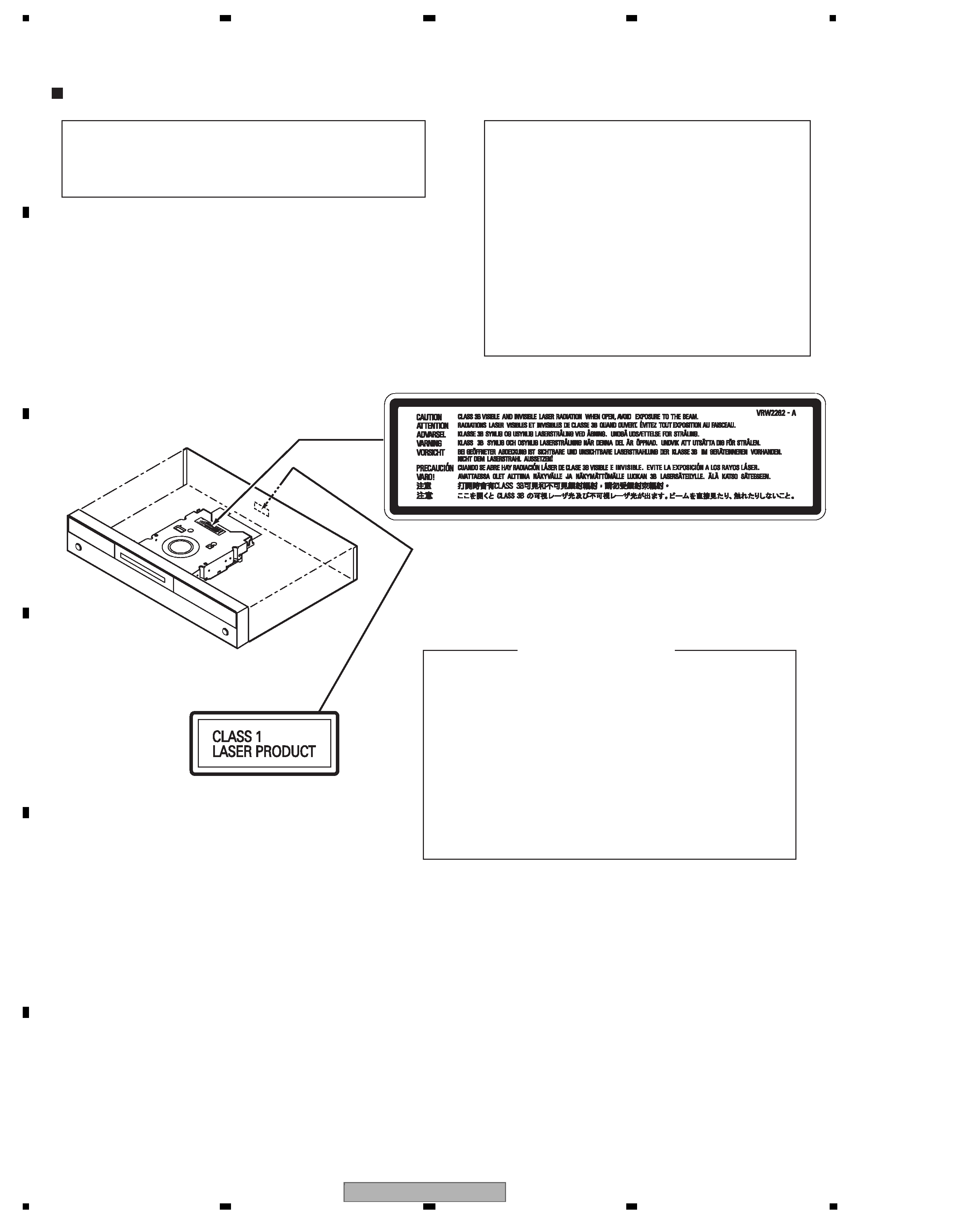
SAFETY INFORMATION
LABEL CHECK
WARNING!
The laser component is capable of emitting radiation exceeding
the limit for CLASS 1. A specially instructed person should do
servicing operation of the apparatus.
Laser Pickup specifications and
Laser characteristics
For CD
Wave length : 785nm
Operating output :
Read mode : 1.07mW (CW), Class1
Maximum output : Class1M
For DVD
Wave length : 660nm
Operating output :
Read mode : 1.08mW, Class1
Write mode : 21.89mW (Pulse), Class1M
Maximum output : Class2M
CLAMP signals for detecting the loading state are detected
by the drive CPUs, and the design prevents laser diode
oscillation when the CLAMP signal turns OFF.
In normal operation, if no disc is clamped, the laser diode
oscillation is disabled.
However, the interlock does not always operate in the test
mode.
2. When the cover is opened, close viewing of the objective
lens with the naked eye will cause exposure to a Class 3A
laser beam.
Additional Laser Caution
1. The ON/OFF(ON:low level,OFF:high level) status of the
VRW2262
STA
ND
BY/O
N
REC
DVR-LX60
3
56
7
8
56
7
8
C
D
F
A
B
E
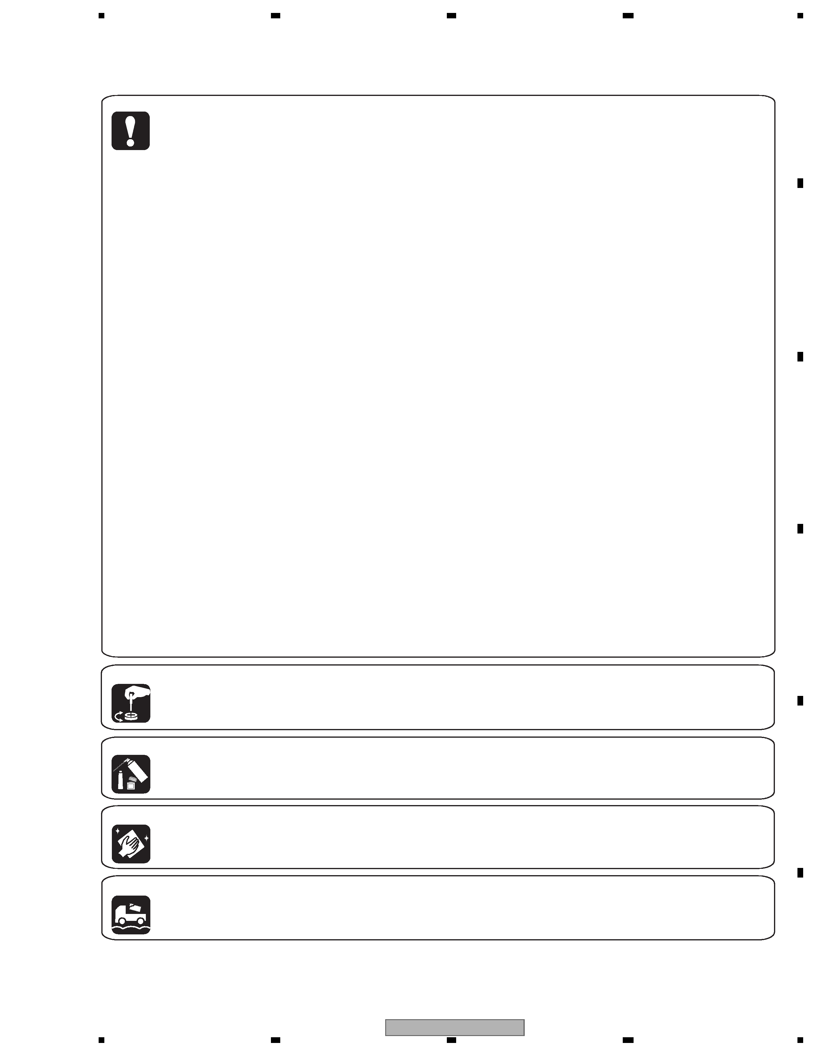
[Important Check Points for Good Servicing]
In this manual, procedures that must be performed during repairs are marked with the below symbol.
Please be sure to confirm and follow these procedures.
1. Product safety
Please conform to product regulations (such as safety and radiation regulations), and maintain a safe servicing environment by
following the safety instructions described in this manual.
Use specified parts for repair.
Use genuine parts. Be sure to use important parts for safety.
Do not perform modifications without proper instructions.
Please follow the specified safety methods when modification(addition/change of parts) is required due to interferences such as
radio/TV interference and foreign noise.
Make sure the soldering of repaired locations is properly performed.
When you solder while repairing, please be sure that there are no cold solder and other debris.
Soldering should be finished with the proper quantity. (Refer to the example)
Make sure the screws are tightly fastened.
Please be sure that all screws are fastened, and that there are no loose screws.
Make sure each connectors are correctly inserted.
Please be sure that all connectors are inserted, and that there are no imperfect insertion.
Make sure the wiring cables are set to their original state.
Please replace the wiring and cables to the original state after repairs.
In addition, be sure that there are no pinched wires, etc.
Make sure screws and soldering scraps do not remain inside the product.
Please check that neither solder debris nor screws remain inside the product.
There should be no semi-broken wires, scratches, melting, etc. on the coating of the power cord.
Damaged power cords may lead to fire accidents, so please be sure that there are no damages.
If you find a damaged power cord, please exchange it with a suitable one.
There should be no spark traces or similar marks on the power plug.
When spark traces or similar marks are found on the power supply plug, please check the connection and advise on secure
connections and suitable usage. Please exchange the power cord if necessary.
Safe environment should be secured during servicing.
When you perform repairs, please pay attention to static electricity, furniture, household articles, etc. in order to prevent injuries.
Please pay attention to your surroundings and repair safely.
2. Adjustments
To keep the original performance of the products, optimum adjustments and confirmation of characteristics within specification.
Adjustments should be performed in accordance with the procedures/instructions described in this manual.
4. Cleaning
For parts that require cleaning, such as optical pickups, tape deck heads, lenses and mirrors used in projection monitors, proper
cleaning should be performed to restore their performances.
3. Lubricants, Glues, and Replacement parts
Use grease and adhesives that are equal to the specified substance.
Make sure the proper amount is applied.
5. Shipping mode and Shipping screws
To protect products from damages or failures during transit, the shipping mode should be set or the shipping screws should be
installed before shipment. Please be sure to follow this method especially if it is specified in this manual.

DVR-LX60
4
12
34
1
234
C
D
F
A
B
E
CONTENTS
SAFETY INFORMATION..................................................................................................................................... 2
1. SERVICE PRECAUTIONS ............................................................................................................................... 6
1.1 NOTES ON SOLDERING .......................................................................................................................... 6
1.2 NOTES ON HANDLING THE HDD............................................................................................................ 7
1.3 NOTES ON REPLACEMENT OF THE SDRAM ........................................................................................ 9
1.4 NOTE ON INSULATORS AND THEIR SET SCREWS.............................................................................. 9
2. SPECIFICATIONS.......................................................................................................................................... 10
2.1 ACCESSORIES ....................................................................................................................................... 10
2.2 SPECIFICATIONS ....................................................................................................................................11
2.3 DISC/CONTENT FORMAT ...................................................................................................................... 13
2.4 PANEL FACILITIES.................................................................................................................................. 17
3. BASIC ITEMS FOR SERVICE........................................................................................................................ 22
3.1 CHECK POINTS AFTER SERVICING..................................................................................................... 22
3.2 QUICK REFERENCE............................................................................................................................... 23
3.3 PCB LOCATIONS .................................................................................................................................... 24
3.4 JIGS LIST ................................................................................................................................................ 25
4. BLOCK DIAGRAM.......................................................................................................................................... 26
4.1 OVERALL WIRING DIAGRAM ................................................................................................................ 26
4.2 OVERALL BLOCK DIAGRAM.................................................................................................................. 28
4.3 DETECTION AND ENCODE SYSTEM BLOCK DIAGRAM..................................................................... 30
4.4 POWER BLOCK DIAGRAM..................................................................................................................... 31
5. DIAGNOSIS.................................................................................................................................................... 32
5.1 SETUP SEQUENCE................................................................................................................................ 32
5.2 DIAGNOSIS OF THE MAIN ASSY .......................................................................................................... 33
6. SERVICE MODE ............................................................................................................................................ 37
6.1 VERSION INFORMATION, ETC. (FIRST SCREEN) ............................................................................... 39
6.2 ATA/ATAPI DEBUG SCREEN (SECOND SCREEN) ............................................................................... 44
6.3 VR-RECORDING-RELATED ERROR LOGS (FOURTH SCREEN) ........................................................ 46
6.4 VR-PLAYBACK-RELATED ERROR LOGS (FIFTH SCREEN) ................................................................ 50
6.5 DV SERVICE MODE................................................................................................................................ 53
6.6 EPG SERVICE MODE ............................................................................................................................. 56
6.7 HDMI SERVICE MODE ........................................................................................................................... 58
6.8 AGING MODE.......................................................................................................................................... 60
6.9 USB CHECK MODE ................................................................................................................................ 62
6.10 HDD CHECK MODE .............................................................................................................................. 63
7. DISASSEMBLY .............................................................................................................................................. 69
8. EACH SETTING AND ADJUSTMENT ........................................................................................................... 74
8.1 MODEL SETTING.................................................................................................................................... 74
8.2 LD POWER ADJUSTMENT..................................................................................................................... 75
8.3 CPRM ID NUMBER AND DATA SETTING .............................................................................................. 79
8.4 FIRMWARE UPDATE METHOD.............................................................................................................. 83
8.5 VIDEO ADJUSTMENT FOR SPECIFIC AREA........................................................................................ 86
9. EXPLODED VIEWS AND PARTS LIST.......................................................................................................... 90
9.1 PACKING ................................................................................................................................................. 90
9.2 EXTERIOR SECTION.............................................................................................................................. 92
9.3 FRONT PANEL SECTION ....................................................................................................................... 94
9.4 SERVICE LOADER MAIN SECTION....................................................................................................... 98
10. SCHEMATIC DIAGRAM............................................................................................................................. 100
10.1 SERVICE TUSB ASSY (1/4)................................................................................................................ 100
10.2 SERVICE TUSB ASSY (2/4)................................................................................................................ 102
10.3 SERVICE TUSB ASSY (3/4)................................................................................................................ 104
10.4 SERVICE TUSB ASSY (4/4)................................................................................................................ 106
10.5 SERVICE FLKY ASSY......................................................................................................................... 108
10.6 SERVICE MAIN ASSY (1/5) .................................................................................................................110
10.7 SERVICE MAIN ASSY (2/5) .................................................................................................................112
10.8 SERVICE MAIN ASSY (3/5) .................................................................................................................114
10.9 SERVICE MAIN ASSY (4/5) .................................................................................................................116
10.10 SERVICE MAIN ASSY (5/5) ...............................................................................................................118
10.11 VDEC ASSY....................................................................................................................................... 120
10.12 SERVICE DVUB ASSY...................................................................................................................... 122
10.13 POWER SUPPLY ASSY .................................................................................................................... 124
10.14 WAVE FORMS................................................................................................................................... 126
11. PCB CONNECTION DIAGRAM.................................................................................................................. 131
11.1 SERVICE TUSB ASSY ........................................................................................................................ 132
11.2 SERVICE FLKY ASSY ......................................................................................................................... 136

DVR-LX60
5
56
7
8
56
7
8
C
D
F
A
B
E
11.3 SERVICE FRJB ASSY..........................................................................................................................138
11.4 SERVICE MAIN ASSY..........................................................................................................................140
11.5 VDEC ASSY .........................................................................................................................................144
11.6 SERVICE DVUB ASSY.........................................................................................................................148
11.7 POWER SUPPLY ASSY.......................................................................................................................150
12. PCB PARTS LIST........................................................................................................................................152
13. IC INFORMATION.......................................................................................................................................179