ORDER NO.
PIONEER ELECTRONIC CORPORATION 4-1, Meguro 1-Chome, Meguro-ku, Tokyo 153-8654, Japan
PIONEER ELECTRONICS SERVICE, INC. P.O. Box 1760, Long Beach, CA 90801-1760, U.S.A.
PIONEER ELECTRONIC (EUROPE) N.V. Haven 1087, Keetberglaan 1, 9120 Melsele, Belgium
PIONEER ELECTRONICS ASIACENTRE PTE. LTD. 253 Alexandra Road, #04-01, Singapore 159936
PIONEER ELECTRONIC CORPORATION 1999
c
DVL-919
RRV2089
1. SAFETY INFORMATION ...................................... 2
2. EXPLODED VIEWS AND PARTS LIST ................ 4
3. SCHEMATIC DIAGRAM ..................................... 16
4. PCB CONNECTION DIAGRAM .......................... 42
5. PCB PARTS LIST ............................................... 58
6. ADJUSTMENT .................................................... 65
CONTENTS
7. GENERAL INFORMATION ................................ 80
7.1 PARTS ......................................................... 80
7.1.1 IC ........................................................... 80
7.2 DISASSEMBLY/ASSEMBLY ....................... 82
7.3 BLOCK DIAGRAM ....................................... 84
8. PANEL FACILITIES AND SPECIFICATIONS .... 86
T IZE JAN. 1999 Printed in Japan
DVD LD PLAYER
Type
Power Requirement
The voltage can be converted by
the following method.
Model
DVL-919
THIS MANUAL IS APPLICABLE TO THE FOLLOWING MODEL(S) AND TYPE(S).
Region No.
KU/CA
AC120V
1
RD/RA
AC110-127/220-240V
1
Automatic select
2
DVL-919
1. SAFETY INFORMATION
This service manual is intended for qualified service technicians ; it is not meant for the casual do-it-
yourselfer. Qualified technicians have the necessary test equipment and tools, and have been trained
to properly and safely repair complex products such as those covered by this manual.
Improperly performed repairs can adversely affect the safety and reliability of the product and may
void the warranty. If you are not qualified to perform the repair of this product properly and safely, you
should not risk trying to do so and refer the repair to a qualified service technician.
WARNING
This product contains lead in solder and certain electrical parts contain chemicals which are known to the state of California to cause
cancer, birth defects or other reproductive harm.
Health & Safety Code Section 25249.6 Proposition 65
NOTICE
(FOR CANADIAN MODEL ONLY)
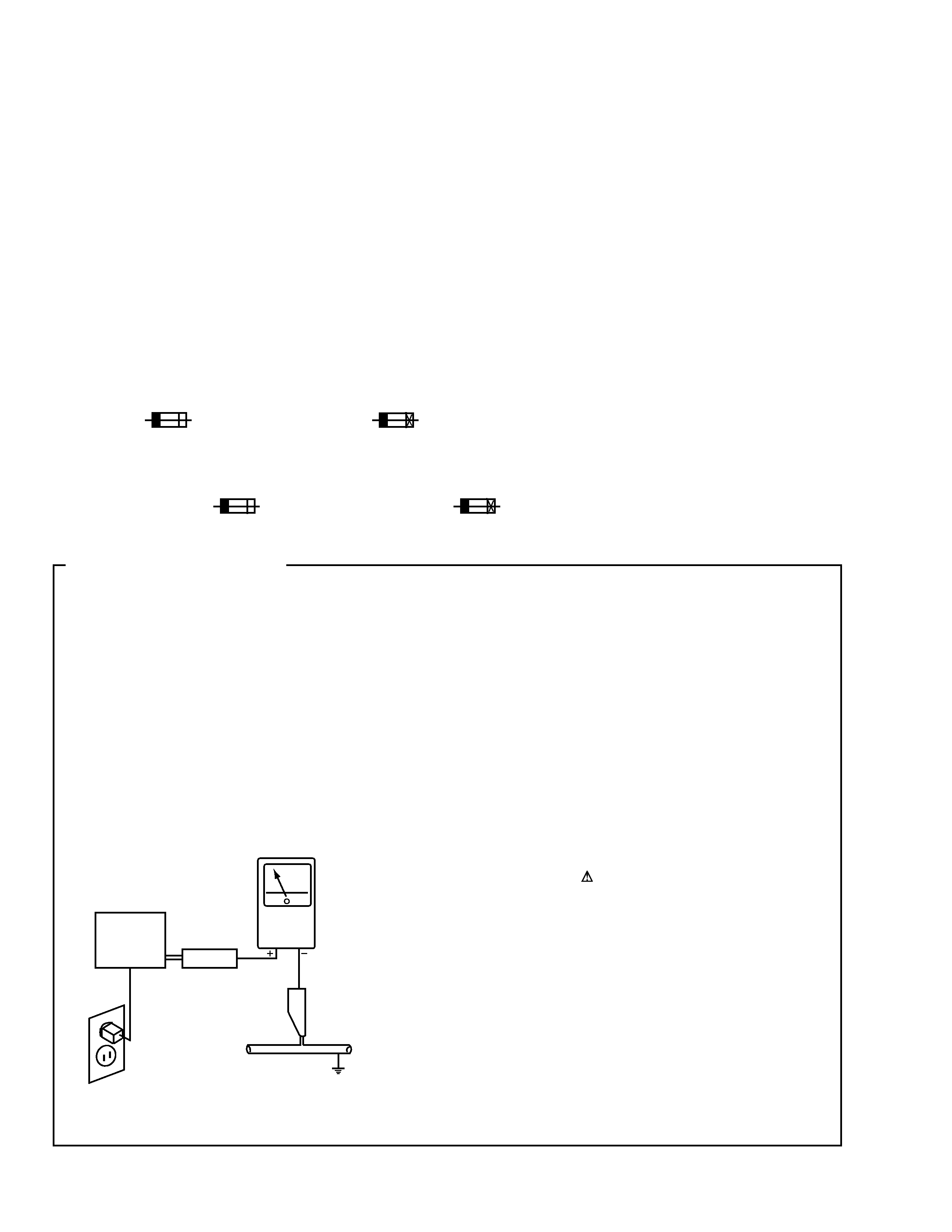
Fuse symbols
(fast operating fuse) and/or
(slow operating fuse) on PCB indicate that replacement parts must
be of identical designation.
REMARQUE
(POUR MODÈLE CANADIEN SEULEMENT)
Les symboles de fusible
(fusible de type rapide) et/ou
(fusible de type lent) sur CCI indiquent que les pièces
de remplacement doivent avoir la même désignation.
ANY MEASUREMENTS NOT WITHIN THE LIMITS
OUTLINED ABOVE ARE INDICATIVE OF A POTENTIAL
SHOCK HAZARD AND MUST BE CORRECTED BEFORE
RETURNING THE APPLIANCE TO THE CUSTOMER.
2. PRODUCT SAFETY NOTICE
Many electrical and mechanical parts in the appliance
have special safety related characteristics. These are
often not evident from visual inspection nor the protection
afforded by them necessarily can be obtained by using
replacement components rated for voltage, wattage, etc.
Replacement parts which have these special safety
characteristics are identified in this Service Manual.
Electrical components having such features are identified
by marking with a
on the schematics and on the parts list
in this Service Manual.
The use of a substitute replacement component which does
not have the same safety characteristics as the PIONEER
recommended replacement one, shown in the parts list in
this Service Manual, may create shock, fire, or other hazards.
Product Safety is continuously under review and new
instructions are issued from time to time. For the latest
information, always consult the current PIONEER Service
Manual. A subscription to, or additional copies of, PIONEER
Service Manual may be obtained at a nominal charge from
PIONEER.
1. SAFETY PRECAUTIONS
The following check should be performed for the
continued protection of the customer and service
technician.
LEAKAGE CURRENT CHECK
Measure leakage current to a known earth ground (water
pipe, conduit, etc.) by connecting a leakage current tester
such as Simpson Model 229-2 or equivalent between the
earth ground and all exposed metal parts of the appliance
(input/output terminals, screwheads, metal overlays, control
shaft, etc.). Plug the AC line cord of the appliance directly
into a 120V AC 60Hz outlet and turn the AC power switch
on. Any current measured must not exceed 0.5mA.
(FOR USA MODEL ONLY)
Leakage
current
tester
Reading should
not be above
0.5mA
Device
under
test
Test all
exposed metal
surfaces
Also test with
plug reversed
(Using AC adapter
plug as required)
Earth
ground
AC Leakage Test

3
DVL-919
Additional Laser Caution
1. The ON/OFF statuses of the side-A/B detection switch
(Lever switch connecting to the TNMB assy), slider-position
detection switches (INNER and OUTER on the PKSB assy),
loading-status detection switches (SW1, 2 and 3 on the LMSB
assy), side B inside detection switch (S901 on the BISB assy)
and CLD pickup active detection switch (S903 on the LCSB
assy) are detected by the microprocessor (IC101 in the CLDM
assy). Also the DVD pickup active detection switch (S902
on the DCSB assy) is detected by the microprocessor (IC501
in the DVDM assy).
· To permit the laser diode of CLD pickup to oscillate, it is
required to set the CLD pickup active detection switch (S903 :
OFF) and the slider-position detection switches for the LD
ACTIVE status (INNER : OFF, OUTER: OFF), and to set the
loading-status detection switches for tilt neutral state (SW1 :
ON, SW2 : OFF, SW3 : ON). As long as these requirements
are not satisfied, the laser diode will not oscillate. When the
requirements are met in any way, the laser diode can oscillate.
The laser diode oscillation will continue if pin 13 of IC801 is
shorted to GND or the emitter and collector of Q834 are shorted
each other (fault condition) in the CLDM assy.
· To permit the laser diode of DVD pickup to oscillate, it is
required to set the DVD pickup active detection switch (S902
:OFF) and each switch and a state of laser diode are contents
same as state of CLD pickup mentioned above. The laser
diode oscillation will continue if pin 13 of IC101 is shorted to
+5V (fault condition) in the DVDM assy.
In the test mode
, the laser diode oscillates when the micro-
processor detects a PLAY signal, or when the PLAY key is
pressed (S104 ON in the FLKY assy), with the above require-
ments satisfied.
2. When the cover is open, close viewing through the objective
lens with the naked eye will cause exposure to a Class 1
laser beam.
: Refer to page 68.
IMPORTANT
THIS PIONEER APPARATUS CONTAINS
LASER OF CLASS 1.
SERVICING OPERATION OF THE APPARATUS
SHOULD BE DONE BY A SPECIALLY
INSTRUCTED PERSON.
LASER DIODE CHARACTERISTICS
·FOR DVD
MAXIMUM OUTPUT POWER : 7 mW
WAVELENGTH : 650 nm
·FOR CD/LD
MAXIMUM OUTPUT POWER : 5 mW
WAVELENGTH : 780-785 nm
DVL-919
4
2. EXPLODED VIEWS AND PARTS LIST
Parts marked by "NSP" are generally unavailable because they are not in our Master Spare Parts List.
The
mark found on some component parts indicates the importance of the safety factor of the part.
Therefore, when replacing, be sure to use parts of identical designation.
Screws adjacent to
mark on product are used for disassembly.
NOTES:
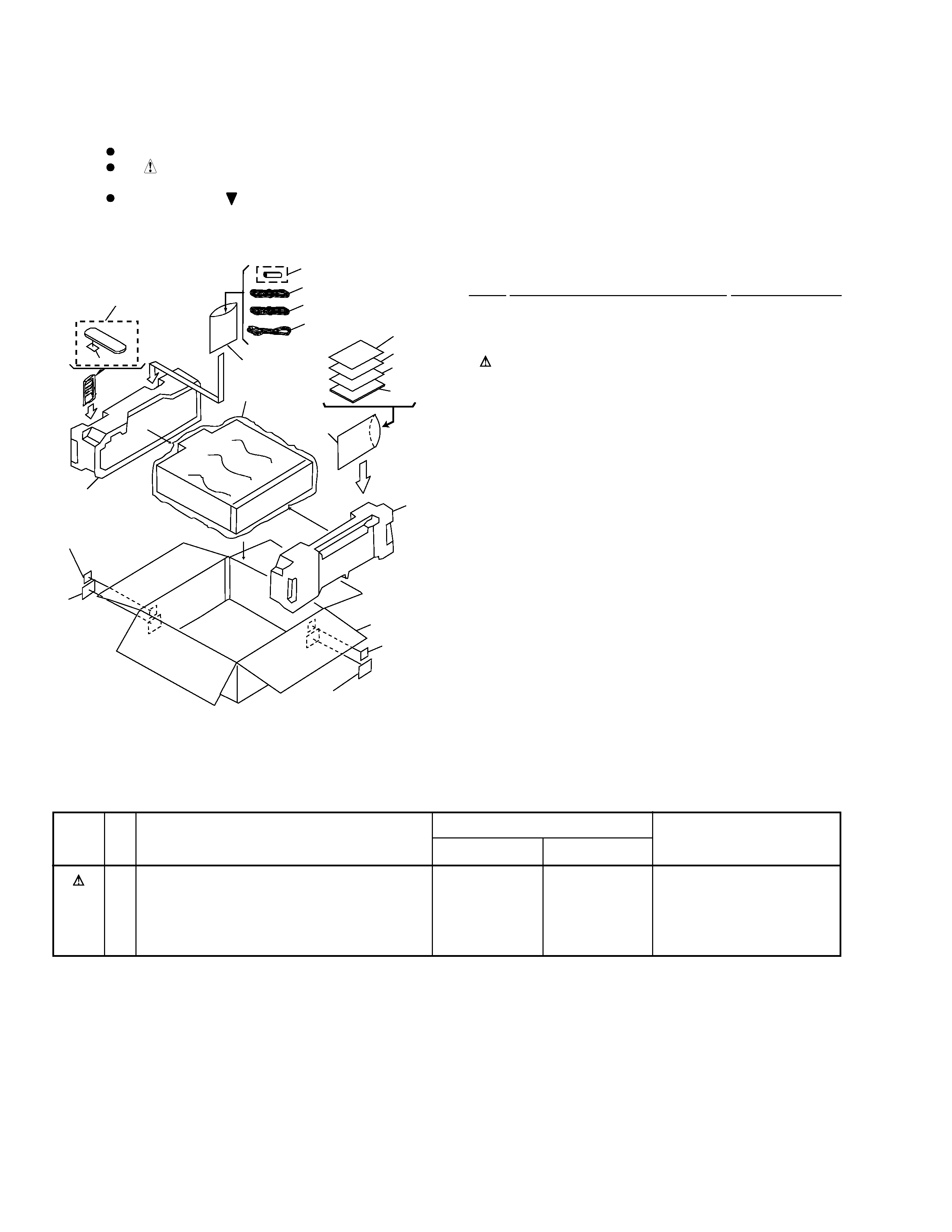
2.1 PACKING
(2) CONTRAST TABLE
DVL-919/KU/CA and RD/RA are constructed the same except for the following :
7
1
2
3
4
5
8
9
10
11
13
14
15
5
12
17
17
6
(RD/RA Type Only)
(RD/RA
Type Only)
18
(RD/RA Type)
18 (RD/RA Type)
Mark
4
POWER CORD
ADG7021
ADG7003
NSP
11
WARRANTY CARD
ARY7023
ARY7025
15
PACKING CASE
VHG1768
VHG1770
17
REGION LABEL P1
Not used
VRW1708
18
RD/RA LABEL
Not used
VRW1711
Remarks
Part No.
KU/CA type
RD/RA type
Symbol and Description
No.
Mark No.
Description
Part No.
NSP
1
DRY CELL BATTERY(R6P,AA) VEM-013
2
VIDEO CORD(L=1.5m)
VDE1036
3
AUDIO CORD(L=1.5m)
VDE1033
4
POWER CORD
See Contrast table (2)
5
POLYETHYLENE BAG
Z21-038
6
REMOTE CONTROL UNIT
VXX2609
(CU-DV030)
7
BATTERRY COVER
VNK3703
NSP
8
CAUTION
VRM1063
9
OPERATING INSTRUCTIONS
VRB1202
(English/French)
10
ERRATA
VRX1031
NSP
11
WARRANTY CARD
See Contrast table (2)
12
MIRROR MAT SHEET
VHL1018
13
PAD F
VHA1226
14
PAD R
VHA1227
15
PACKING CASE
See Contrast table (2)
16
· · · · ·
17
REGION LABEL P1
See Contrast table (2)
18
RD/RA LABEL
See Contrast table (2)
(1) PACKING PARTS LIST
DVL-919
5
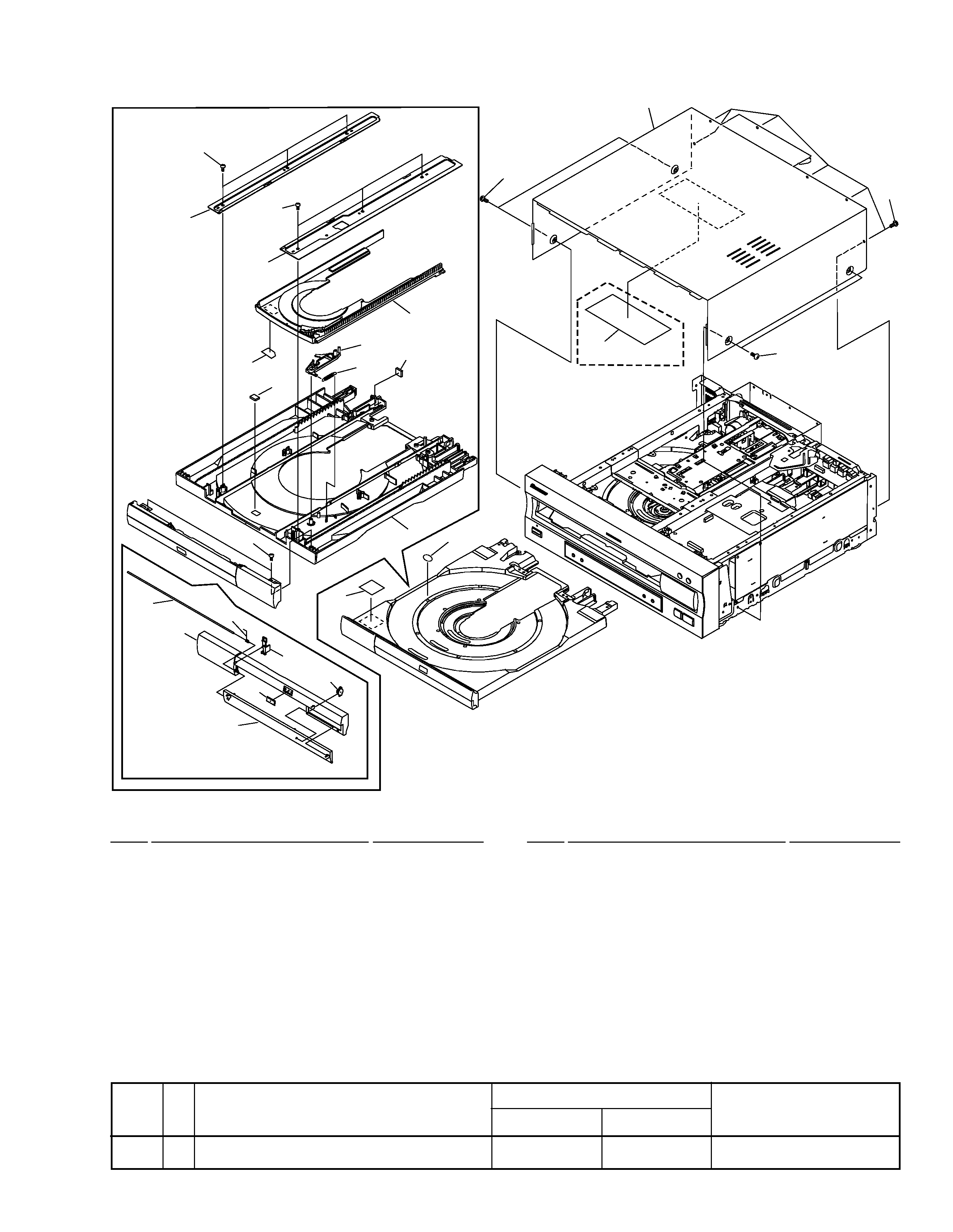
1
8
7
5
9
10
14
13
19
19
19
15
12
18
11
19
20
21
KU/CA Type only
20
2x12
3
4
6
16
17
4
Mark No.
Description
Part No.
1
LD TRAY ASSY
VXA2173
2
CUSHION
VEC1682
NSP
3
CARRY LABEL
VRW1289
4
DAMP CUSHION
VEC1683
5
CD TRAY
VNK3922
6
TRAY LABEL
VRW1628
7
GUIDE PLATE (R)
VNE1939
8
GUIDE PLATE (L)
VNE1938
9
LOCK PLATE
VNL1703
10
LOCK PLATE SPRING
VBH1188
(1) EXTERIOR SECTION PARTS LIST
11
TRAY PANEL
VNK4355
12
DVD DOOR
VNK4356
13
DOOR SPRING
VBH1248
14
DOOR HOLDER
VNL1817
15
DAMPER ASSY
VXA1999
16
DVD PLATE
VAM1075
17
BONNET CASE S
VXX2561
18
DOOR SHAFT
VLL1506
19
SCREW
BBZ30P080FMC
20
SCREW
BCZ40P060FZK
21
65 LABEL
See Contrast table (2)
Mark No.
Description
Part No.
2.2 EXTERIOR SECTION
(2) CONTRAST TABLE
DVL-919/KU/CA and RD/RA are constructed the same except for the following :
Mark
21
65 LABEL
ARW7050
Not used
Remarks
Part No.
KU/CA type
RD/RA type
Symbol and Description
No.