ORDER NO.
PIONEER CORPORATION 4-1, Meguro 1-chome, Meguro-ku, Tokyo 153-8654, Japan
PIONEER ELECTRONICS (USA) INC. P.O. Box 1760, Long Beach, CA 90801-1760, U.S.A.
PIONEER EUROPE NV Haven 1087, Keetberglaan 1, 9120 Melsele, Belgium
PIONEER ELECTRONICS ASIACENTRE PTE. LTD. 253 Alexandra Road, #04-01, Singapore 159936
PIONEER CORPORATION 2004
DVH-P5650MP/RC
CRT3264
MULTI-CD CONTROL HIGH POWER DVD/VIDEO CD/CD/MP3/WMA PLAYER WITH FM/AM TUNER
DVH-P5650MP
/RC
DVH-P5650MP/RD
This service manual should be used together with the following manual(s):
Model No.
Order No.
Mech.Module
Remarks
CX-3078
CRT3257
MS-3V1
DVD Mech. Module:Circuit Description, Mech. Description, Disassembly
For details, refer to "Important symbols for good services".
K-ZZA. MAY 2004 printed in Japan
DVH-P5650MP/RC
2
12
34
12
3
4
C
D
F
A
B
E
SAFETY INFORMATION
[ Important symbols for good services ]
In this manual, the symbols shown-below indicate that adjustments, settings or cleaning should be made securely.
When you find the procedures bearing any of the symbols, be sure to fulfill them:
2. Adjustments
To keep the original performances of the product, optimum adjustments or specification confirmation is indispensable.
In accordance with the procedures or instructions described in this manual, adjustments should be performed.
3. Cleaning
For optical pickups, tape-deck heads, lenses and mirrors used in projection monitors, and other parts requiring cleaning,
proper cleaning should be performed to restore their performances.
5. Lubricants, glues, and replacement parts
Appropriately applying grease or glue can maintain the product performances. But improper lubrication or applying
glue may lead to failures or troubles in the product. By following the instructions in this manual, be sure to apply the
prescribed grease or glue to proper portions by the appropriate amount.For replacement parts or tools, the prescribed
ones should be used.
4. Shipping mode and shipping screws
To protect the product from damages or failures that may be caused during transit, the shipping mode should be set or
the shipping screws should be installed before shipping out in accordance with this manual, if necessary.
1. Product safety
You should conform to the regulations governing the product (safety, radio and noise, and other regulations), and
should keep the safety during servicing by following the safety instructions described in this manual.
- Service Precaution
1. You should conform to the regulations governing
the product (safety, radio and noise, and other
regulations), and should keep the safety during
servicing by following the safety instructions
described in this manual.
2. Before disassembling the unit, be sure to turn off
the power. Unplugging and plugging the connectors
during power-on mode may damage the ICs inside
the unit.
3. To protect the pickup unit from electrostatic discharge
during servicing, take an appropriate treatment
(shorting-solder) by referring to "the DISASSEMBLY"
on page 73.
4. After replacing the pickup unit, be sure to skew
adjustment. (See page 61.)
5. During disassembly, be sure to turn the power off since
an internal IC might be destroyed when a connector
is plugged or unplugged.
6. To avoid malfunctions after finishing DVD mechanism
test mode, you must execute the following steps to
clear the memory and leave the mode:
(1) Turn off the back-up and ACC.
(2) Wait 10 seconds.
(3) Turn on ACC.
(4) Turn on the back-up.
This service manual is intended for qualified service technicians; it is not meant for the casual do-it-yourselfer.
Qualified technicians have the necessary test equipment and tools, and have been trained to properly and safely
complex products such as those covered by this manual.
Improperly performed repairs can adversely affect the safety and reliability of the product and may void the
If you are not qualified to perform the repair of this product properly and safely, you should not risk
and refer the repair to a qualified service technician.
repair
warranty.
trying to do so
is a trademark of DVD Format/Logo Licensing Corporation.

DVH-P5650MP/RC
3
56
7
8
56
7
8
C
D
F
A
B
E
CONTENTS
SAFETY INFORMATION......................................................................................................................................2
1. SPECIFICATIONS .............................................................................................................................................4
2. EXPLODED VIEWS AND PARTS LIST.............................................................................................................6
2.1 PACKING ....................................................................................................................................................6
2.2 EXTERIOR .................................................................................................................................................8
2.3 DVD MECHANISM MODULE ...................................................................................................................10
3. BLOCK DIAGRAM AND SCHEMATIC DIAGRAM ..........................................................................................12
3.1 BLOCK DIAGRAM ....................................................................................................................................12
3.2 OVERALL CONNECTION DIAGRAM(GUIDE PAGE) ..............................................................................16
3.3 KEYBOARD UNIT ....................................................................................................................................22
3.4 DVD CORE UNIT(MS-3V1)(SODC)(1/2)(GUIDE PAGE)..........................................................................24
3.5 DVD CORE UNIT(MS-3V1)(CPU)(2/2).....................................................................................................30
3.6 COMPOUND UNIT(A), COMPOUND UNIT(B) AND RELAY PCB ...........................................................34
3.7 PU UNIT(REFERENCE)...........................................................................................................................35
4. PCB CONNECTION DIAGRAM ......................................................................................................................36
4.1 TUNER AMP UNIT ...................................................................................................................................36
4.2 KEYBOARD UNIT ....................................................................................................................................40
4.3 PANEL UNIT .............................................................................................................................................41
4.4 DVD CORE UNIT(MS-3V1) ......................................................................................................................42
4.5 COMPOUND UNIT(A), COMPOUND UNIT(B) AND RELAY PCB ...........................................................46
5. ELECTRICAL PARTS LIST .............................................................................................................................47
6. ADJUSTMENT ................................................................................................................................................57
6.1 JIG CONNECTION DIAGRAM .................................................................................................................57
6.2 DVD ADJUSTMENT .................................................................................................................................58
6.3 DC-DC CONVERTER FREQUENCY ADJUSTMENT AND FREQUENCY CHECK FOR CLOCK ..........72
7. GENERAL INFORMATION .............................................................................................................................73
7.1 DIAGNOSIS ..............................................................................................................................................73
7.1.1 DISASSEMBLY......................................................................................................................................73
7.1.2 CONNECTOR FUNCTION DESCRIPTION ..........................................................................................76
7.2 PARTS ......................................................................................................................................................77
7.2.1 IC ...........................................................................................................................................................77
7.2.2 DISPLAY ................................................................................................................................................94
7.3 OPERATIONAL FLOW CHART ................................................................................................................95
7.4 CLEANING ...............................................................................................................................................96
8. OPERATIONS .................................................................................................................................................97
DVH-P5650MP/RC
4
12
34
12
3
4
C
D
F
A
B
E
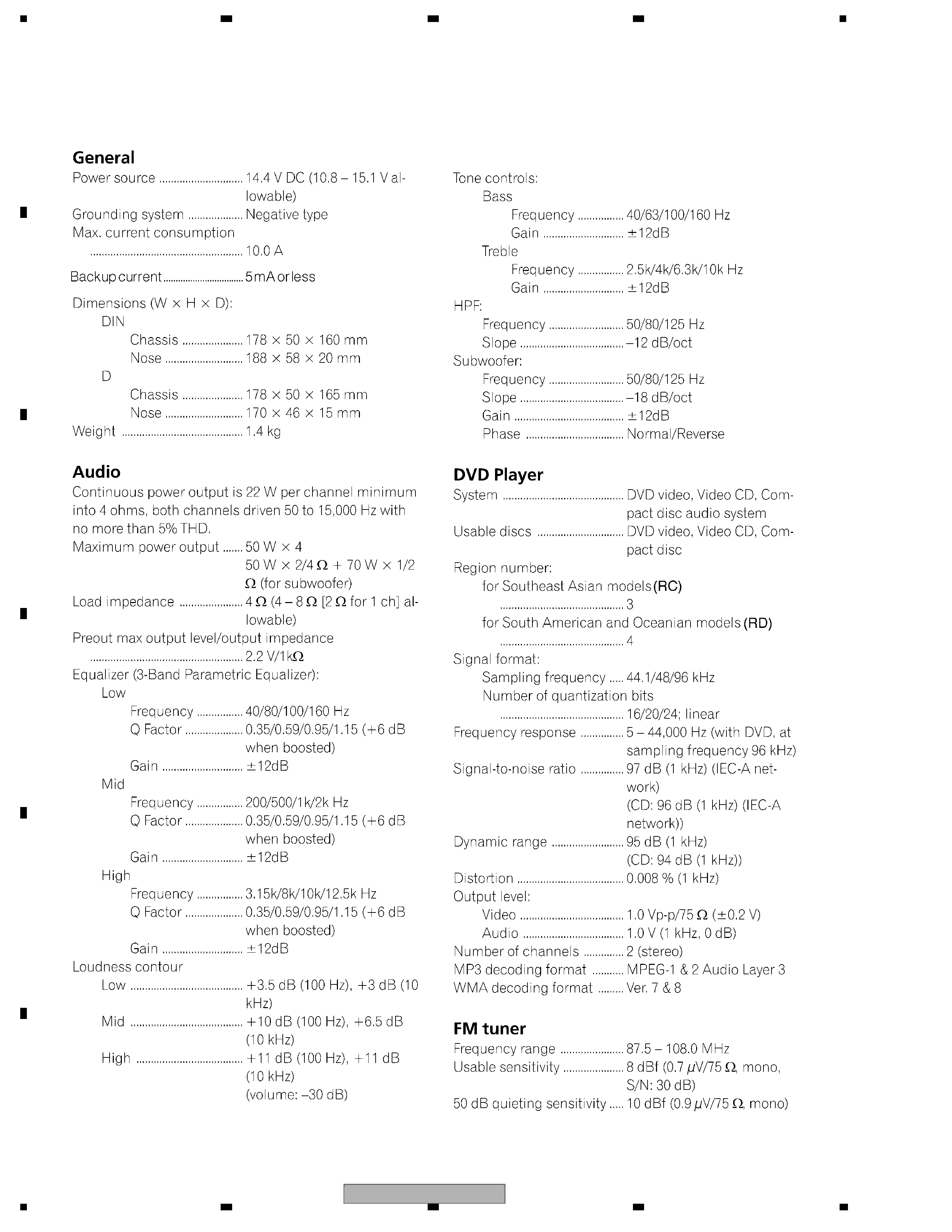
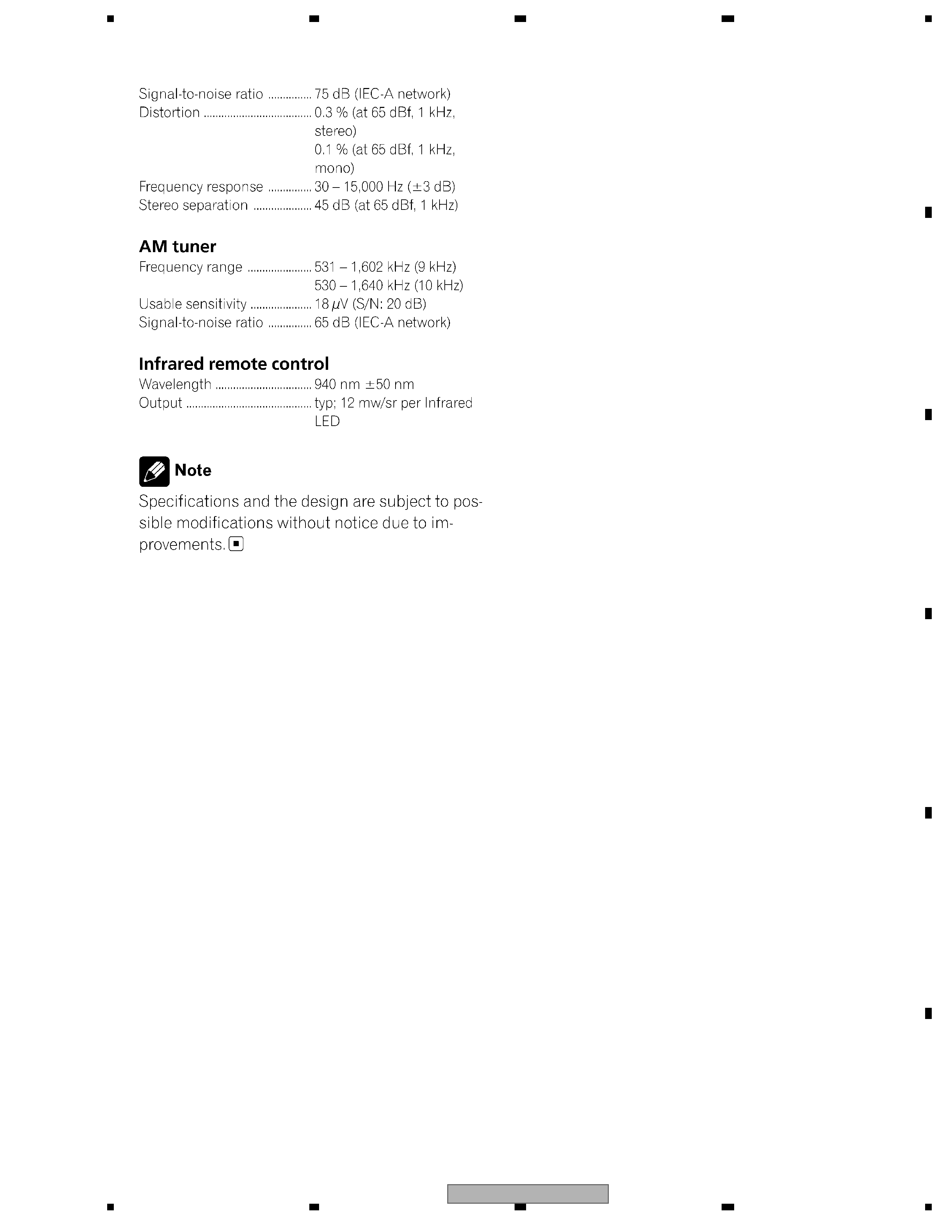
1. SPECIFICATIONS
DVH-P5650MP/RC
5
56
7
8
56
7
8
C
D
F
A
B
E