ORDER NO.
PIONEER CORPORATION 4-1, Meguro 1-chome, Meguro-ku, Tokyo 153-8654, Japan
PIONEER ELECTRONICS SERVICE, INC. P.O. Box 1760, Long Beach, CA 90801-1760, U.S.A.
PIONEER ELECTRONIC (EUROPE) N.V. Haven 1087, Keetberglaan 1, 9120 Melsele, Belgium
PIONEER ELECTRONICS ASIACENTRE PTE. LTD. 253 Alexandra Road, #04-01, Singapore 159936
PIONEER CORPORATION 1999
c
Type
Model
Power Requirement
Region No.
Remarks
DV-F727
DV-F07
KU
AC120V
1
KC
AC120V
1
KU/RC
AC120V
3
KU/CA
AC120V
1
DV-F727
RRV2236
1. SAFETY INFORMATION ....................................... 2
2. EXPLODED VIEWS AND PARTS LIST ................. 3
3. BLOCK DIAGRAM AND SCHEMATIC DIAGRAM .. 12
4. PCB CONNECTION DIAGRAM ........................... 39
5. PCB PARTS LIST ................................................ 55
6. ADJUSTMENT ..................................................... 62
CONTENTS
7. GENERAL INFORMATION .................................. 66
7.1 DIAGNOSIS ................................................... 66
7.1.1 TEST MODE SCREEN DISPLAY ............. 66
7.1.2 TROUBLE SHOOTING ............................ 68
7.1.3 OPERATION FLOW CHART .................... 69
7.1.4 ERROR CODE ......................................... 70
7.1.5 INTERFACE CONNECTOR ..................... 74
7.1.6 DISASSEMBLY ........................................ 77
7.1.7 ABOUT SERVICE IN THE
MECHANISM FAILURE ............................ 79
7.2 PARTS ........................................................... 80
7.2.1 IC ............................................................. 80
7.2.2 DISPLAY .................................................. 95
8. PANEL FACILITIES AND SPECIFICATIONS ....... 96
T IZE DEC. 1999 Printed in Japan
FILE-TYPE DVD PLAYER
DV-F07
THIS MANUAL IS APPLICABLE TO THE FOLLOWING MODEL(S) AND TYPE(S).
STANDBY / ON
STANDBY
ACCESS
AUDIO/VIDEO
UPDATE
CLEAR
PLAY
OPEN/
CLOSE
DIRECT CUSTOM
DISC/
CHARA
PUSH ENTER
KEYBOARD
/MOUSE
SINGLE LOADER
FILE-TYPE DVD MECHANISM
9
8
7
10
6
5
4
3
2
1
TEXT
PLAY MODE
CLEAR
RANDOM
DISPLAY
INPUT
SEARCH
2
DV-F727, DV-F07
1. SAFETY INFORMATION
This service manual is intended for qualified service technicians ; it is not meant for the casual do-it-
yourselfer. Qualified technicians have the necessary test equipment and tools, and have been trained
to properly and safely repair complex products such as those covered by this manual.
Improperly performed repairs can adversely affect the safety and reliability of the product and may
void the warranty. If you are not qualified to perform the repair of this product properly and safely, you
should not risk trying to do so and refer the repair to a qualified service technician.
WARNING
This product contains lead in solder and certain electrical parts contain chemicals which are known to the state of California to cause
cancer, birth defects or other reproductive harm.
Health & Safety Code Section 25249.6 Proposition 65
NOTICE
(FOR CANADIAN MODEL ONLY)
Fuse symbols
(fast operating fuse) and/or
(slow operating fuse) on PCB indicate that replacement parts must
be of identical designation.
REMARQUE
(POUR MODÈLE CANADIEN SEULEMENT)
Les symboles de fusible
(fusible de type rapide) et/ou
(fusible de type lent) sur CCI indiquent que les pièces
de remplacement doivent avoir la même désignation.
ANY MEASUREMENTS NOT WITHIN THE LIMITS
OUTLINED ABOVE ARE INDICATIVE OF A POTENTIAL
SHOCK HAZARD AND MUST BE CORRECTED BEFORE
RETURNING THE APPLIANCE TO THE CUSTOMER.
2. PRODUCT SAFETY NOTICE
Many electrical and mechanical parts in the appliance
have special safety related characteristics. These are
often not evident from visual inspection nor the protection
afforded by them necessarily can be obtained by using
replacement components rated for voltage, wattage, etc.
Replacement parts which have these special safety
characteristics are identified in this Service Manual.
Electrical components having such features are identified
by marking with a
on the schematics and on the parts list
in this Service Manual.
The use of a substitute replacement component which does
not have the same safety characteristics as the PIONEER
recommended replacement one, shown in the parts list in
this Service Manual, may create shock, fire, or other hazards.
Product Safety is continuously under review and new
instructions are issued from time to time. For the latest
information, always consult the current PIONEER Service
Manual. A subscription to, or additional copies of, PIONEER
Service Manual may be obtained at a nominal charge from
PIONEER.
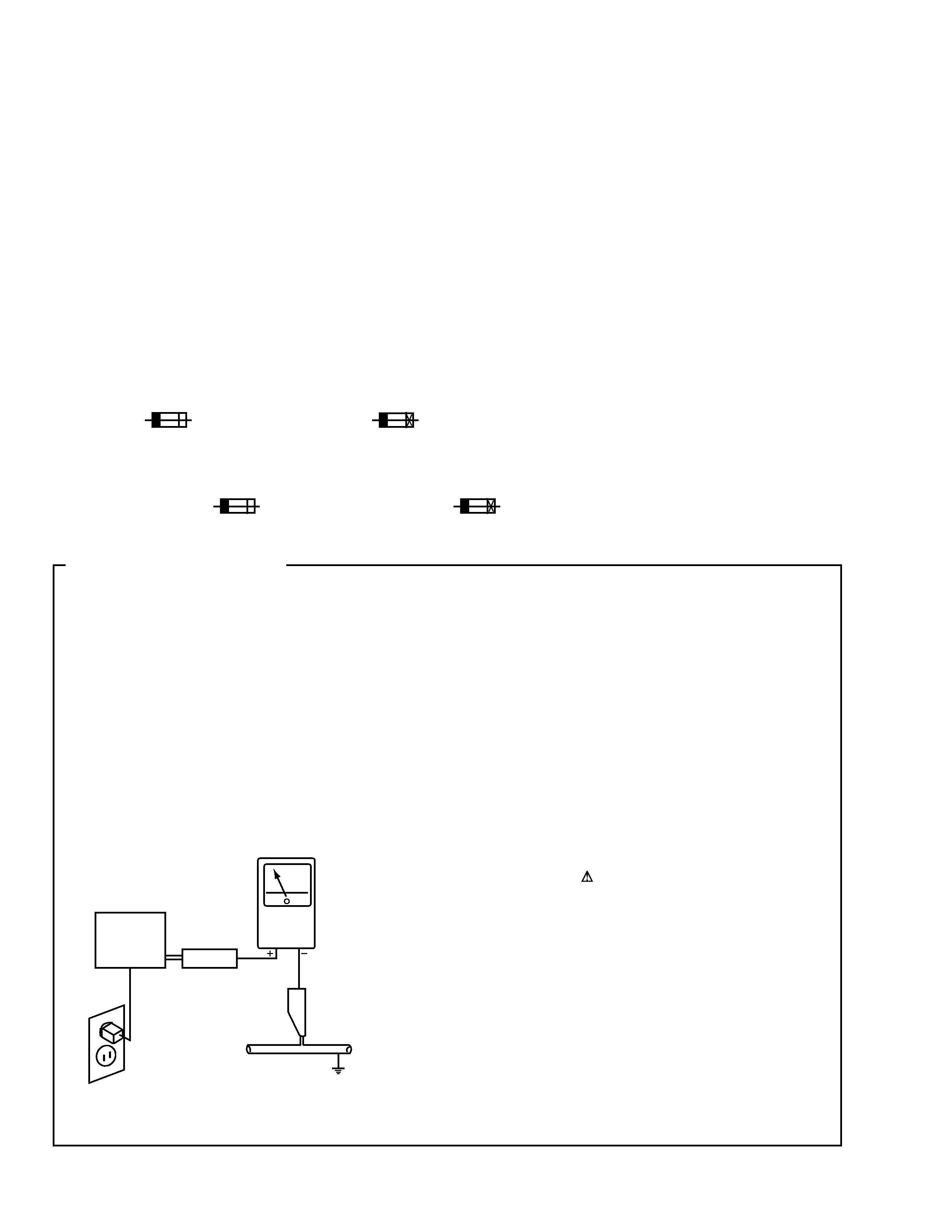
1. SAFETY PRECAUTIONS
The following check should be performed for the
continued protection of the customer and service
technician.
LEAKAGE CURRENT CHECK
Measure leakage current to a known earth ground (water
pipe, conduit, etc.) by connecting a leakage current tester
such as Simpson Model 229-2 or equivalent between the
earth ground and all exposed metal parts of the appliance
(input/output terminals, screwheads, metal overlays, control
shaft, etc.). Plug the AC line cord of the appliance directly
into a 120V AC 60Hz outlet and turn the AC power switch
on. Any current measured must not exceed 0.5mA.
(FOR USA MODEL ONLY)
Leakage
current
tester
Reading should
not be above
0.5mA
Device
under
test
Test all
exposed metal
surfaces
Also test with
plug reversed
(Using AC adapter
plug as required)
Earth
ground
AC Leakage Test
3
DV-F727, DV-F07
9
13
2 (1/2)
2 (2/2)
Except
DV-F727/KU/RC
DV-F727
/KC
Only
15
6
10
11
7
12
3
1
14
14
4
5
8
DV-F727
/KC
Only
DV-F727
/KU/RC
Only
DV-F727/KC
Only
16
DV-F727
/KU/RC
Only
16
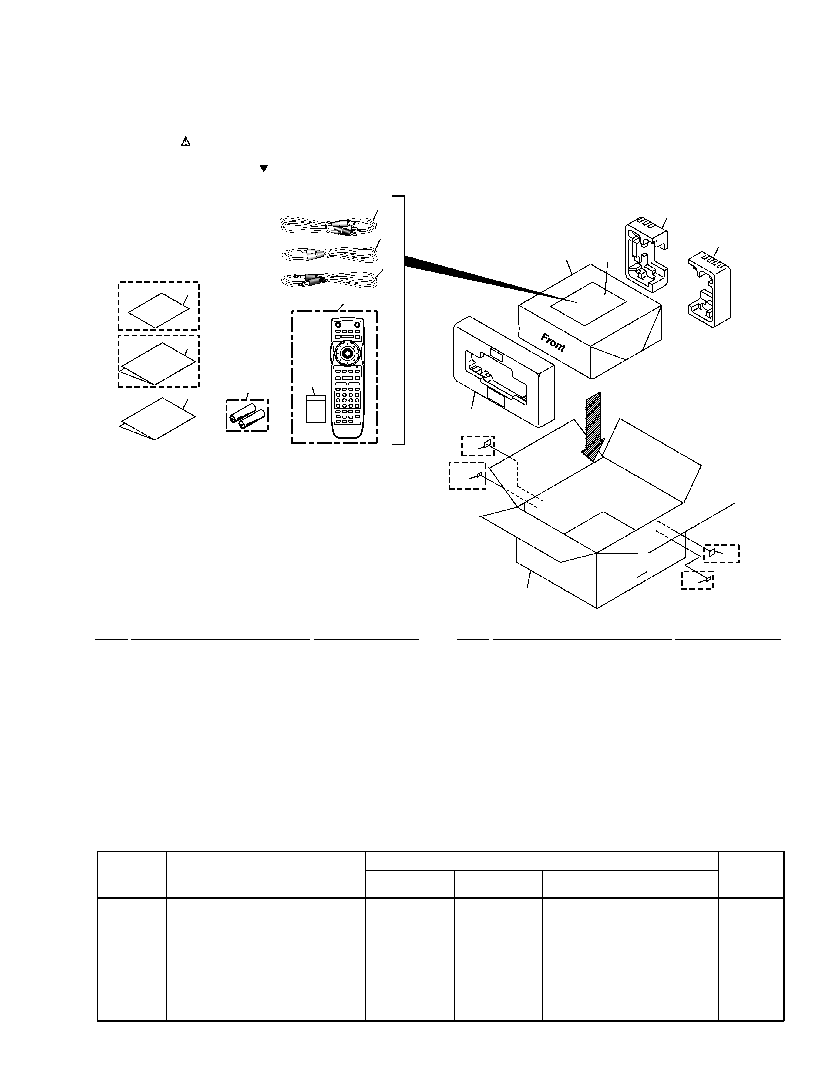
2.1 PACKING
(1) PACKING PARTS LIST
Mark No.
Description
Part No.
2. EXPLODED VIEWS AND PARTS LIST
NOTES:
· Parts marked by "NSP" are generally unavailable because they are not in our Master Spare Parts List.
· The mark found on some component parts indicates the importance of the safety factor of the part.
Therefore, when replacing, be sure to use parts of identical designation.
· Screws adjacent to mark on the product are used for disassembly.
1
Protector F
See Contrast table (2)
2
Protector R
See Contrast table (2)
3
Packing Sheet
RHC1023
4
Packing Case
See Contrast table (2)
5
Polyethylene Bag B5
VHL1051
6
Operating Instructions (English) See Contrast table (2)
7
Remote Control Unit
VXX2629
(CU-DV039)
8
Battery Cover
VNK4423
9
Audio Cord (L = 1.5m)
VDE1033
Mark No.
Description
Part No.
10
Video Cord (L = 1.5m)
VDE1034
11
Master-Slave Control Cord
RDE1023
(L = 0.75m)
NSP
12
Dry Cell Battery (R6P, AA)
VEM-013
NSP
13
Warranty Card
See Contrast table (2)
14
KC Label
See Contrast table (2)
15
Operating Instructions (French) See Contrast table (2)
16
Region Label
See Contrast table (2)
(2) CONTRAST TABLE
DV-F727/KU, KC, KU/RC and DV-F07/KU/CA are constructed the same except for the following :
Mark No.
Symbol and Description
Part No.
Remarks
DV-F727
/KU
DV-F727
/KC
DV-F727
/KU/RC
DV-F07
/KU/CA
NSP
1
2
4
6
13
14
15
16
Protector F
Protector R
Packing Case
Operating Instructions (English)
Warranty Card
KC Label
Operating Instructions (French)
Region Label
PHA1325
PHA1326
VHG1840
VRB1237
ARY7023
Not used
Not used
Not used
PHA1325
PHA1326
VHG1840
VRB1237
ARY7024
VRW1716
VRC1107
Not used
PHA1325
PHA1326
VHG1840
VRB1237
Not used
Not used
Not used
VRW1702
PHA1336
PHA1337
VHG1841
VRB1238
ARY1026
Not used
Not used
Not used
4
DV-F727, DV-F07
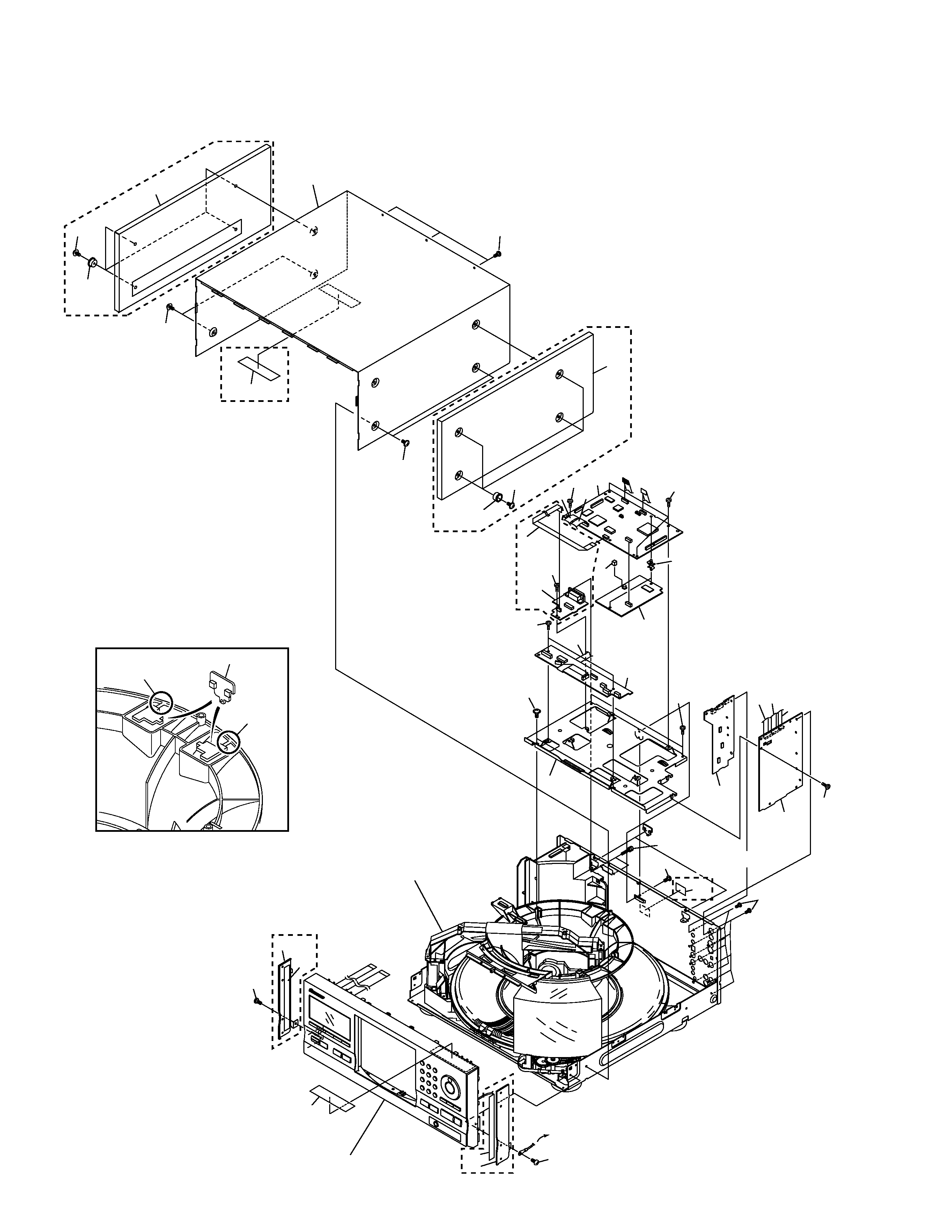
2.2 EXTERIOR SECTION (1/2)
Cut
Cut
Note
1
1
Part of Center Pole
24
25
1
8
2
3
6
4
5
7
9
23
27
22
26
27
29
29
29
30
17
14
29
29
31
29
29
11
12
13
10
15
16
26
28
DV-F727
Only
DV-F727/KU
and
DV-F07/KU/CA
Only
DV-F07
Only
DV-F07
Only
DV-F07
Only
DV-F07
Only
DV-F07
Only
DV-F07
Only
DV-F727/KU/RC
Only
28
DV-F727
Only
29
29
29
29
21
Refer to
"2.5 FRONT PANEL SECTION".
Refer to
"2.3 EXTERIOR SECTION (2/2)".
18
19
20
20
from PS2B Assy
5
DV-F727, DV-F07
(1) EXTERIOR SECTION (1/2) PARTS LIST
Mark No.
Description
Part No.
1
DVDM Assy
See Contrast table (2)
2
232B Assy
See Contrast table (2)
3
VQEB Assy
VWV1669
4
MSJB Assy
See Contrast table (2)
5
AVJB Assy
See Contrast table (2)
6
MDRB Assy
VWG2127
7
Flexible Cable (12P)
VDA1779
8
Flexible Cable (7P)
See Contrast table (2)
9
Flexible Cable (11P)
VDA1781
10
Flexible Cable (12P)
VDA1778
11
Flexible Cable (7P)
VDA1782
12
Flexible Cable (14P)
VDA1707
13
Flexible Cable (15P)
VDA1784
14
Screw (#4-40/M2)
See Contrast table (2)
15
PCB Support Cushion
VEC2079
Mark No.
Description
Part No.
16
PCB Spacer
VEC2077
NSP
17
Main Holder
VNE2215
18
Side MoleR
See Contrast table (2)
19
Side Mole L
See Contrast table (2)
NSP
20
Spacer
See Contrast table (2)
21
Caution Label 301
VRW1817
22
65 Label
See Contrast table (2)
23
Bonnet Case S
See Contrast table (2)
24
Side Wood L
See Contrast table (2)
25
Side Wood R
See Contrast table (2)
26
Wood Collar
See Contrast table (2)
27
Screw
See Contrast table (2)
28
Screw
See Contrast table (2)
29
Screw
BBZ30P080FZK
30
Screw
IPZ30P080FMC
31
Region Label
See Contrast table (2)
(2) CONTRAST TABLE
DV-F727/KU, KC, KU/RC and DV-F07/KU/CA are constructed the same except for the following :
Mark No.
Symbol and Description
Part No.
Remarks
DV-F727
/KU
DV-F727
/KC
DV-F727
/KU/RC
DV-F07
/KU/CA
NSP
1
2
4
5
8
14
18
19
20
22
23
24
25
26
27
28
31
DVDM Assy
232B Assy
MSJB Assy
AVJB Assy
Flexible Cable (7P)
Screw (#4-40/M2)
Side Mole R
Side Mole L
Spacer
65 Label
Bonnet Case S
Side Wood L
Side Wood R
Wood Collar
Screw
Screw
Region Label
VWS1386
Not used
VWG2131
VWV1719
Not used
Not used
Not used
Not used
Not used
ARW7050
VXX2692
Not used
Not used
Not used
Not used
FBT40P080FZK
Not used
VWS1386
Not used
VWG2131
VWV1719
Not used
Not used
Not used
Not used
Not used
Not used
VXX2692
Not used
Not used
Not used
Not used
FBT40P080FZK
Not used
VWS1386
Not used
VWG2131
VWV1719
Not used
Not used
Not used
Not used
Not used
Not used
VXX2692
Not used
Not used
Not used
Not used
FBT40P080FZK
VRW1703
VWS1396
VWG2129
VWG2128
VWV1720
VDA1777
DBA1078
PAN1374
PAN1373
PNM1331
ARW7050
VXX2693
PMM1043
PMM1044
PNW1238
PBA1103
Not used
Not used