ORDER NO.
PIONEER CORPORATION 4-1, Meguro 1-chome, Meguro-ku, Tokyo 153-8654, Japan
PIONEER ELECTRONICS (USA) INC. P.O. Box 1760, Long Beach, CA 90801-1760, U.S.A.
PIONEER EUROPE NV Haven 1087, Keetberglaan 1, 9120 Melsele, Belgium
PIONEER ELECTRONICS ASIACENTRE PTE. LTD. 253 Alexandra Road, #04-01, Singapore 159936
PIONEER CORPORATION 2006
DVD-V8000
RRV3389
DVD PLAYER
DVD-V8000
RACK MOUNT KIT
CB-A802
XJ/WL5
THIS MANUAL IS APPLICABLE TO THE FOLLOWING MODEL(S) AND TYPE(S).
Model
Type
Power Requirement
Region No.
Remarks
DVD-V8000
KUCXJ
AC120 V
1
DVD-V8000
WYXJ5
AC 220 V to 240 V
2
CB-A802
XJ/WL5
For details, refer to "Important symbols for good services".
T-ZZR JULY 2006 printed in Japan
DVD-V8000
2
1234
123
4
C
D
F
A
B
E
SAFETY INFORMATION
This service manual is intended for qualified service technicians ; it is not meant for the casual do-it-
yourselfer. Qualified technicians have the necessary test equipment and tools, and have been trained
to properly and safely repair complex products such as those covered by this manual.
Improperly performed repairs can adversely affect the safety and reliability of the product and may
void the warranty. If you are not qualified to perform the repair of this product properly and safely, you
should not risk trying to do so and refer the repair to a qualified service technician.
WARNING
This product contains lead in solder and certain electrical parts contain chemicals which are known to the state of California to
causecancer, birth defects or other reproductive harm.
Health & Safety Code Section 25249.6 Proposition 65
ANY MEASUREMENTS NOT WITHIN THE LIMITS
OUTLINED ABOVE ARE INDICATIVE OF A POTENTIAL
SHOCK HAZARD AND MUST BE CORRECTED BEFORE
RETURNING THE APPLIANCE TO THE CUSTOMER.
2. PRODUCT SAFETY NOTICE
Many electrical and mechanical parts in the appliance
have special safety related characteristics. These are
often not evident from visual inspection nor the protection
afforded by them necessarily can be obtained by using
replacement components rated for voltage, wattage, etc.
Replacement par ts which have these special safety
characteristics are identified in this Service Manual.
Electrical components having such features are identified
by marking with a
on the schematics and on the parts list
in this Service Manual.
The use of a substitute replacement component which does
not have the same safety characteristics as the PIONEER
recommended replacement one, shown in the parts list in
this Service Manual, may create shock, fire, or other hazards.
Product Safety is continuously under review and new
instructions are issued from time to time. For the latest
information, always consult the current PIONEER Service
Manual. A subscription to, or additional copies of, PIONEER
Service Manual may be obtained at a nominal charge
from PIONEER.
1. SAFETY PRECAUTIONS
The following check should be performed for the
continued protection of the customer and
ser vice technician.
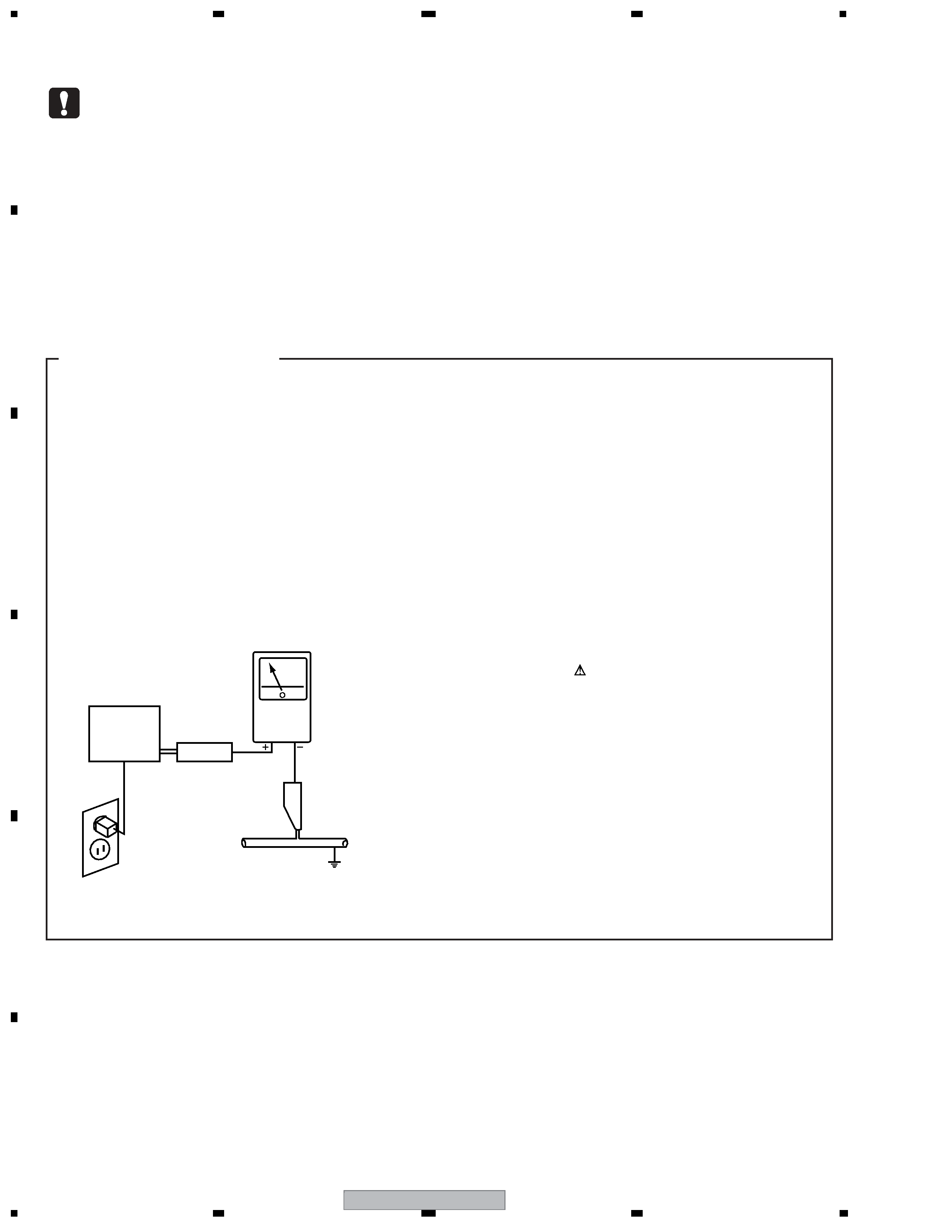
LEAKAGE CURRENT CHECK
Measure leakage current to a known earth ground (waterpipe
, conduit, etc.) by connecting a leakage current tester
such as Simpson Model 229-2 or equivalent between the
earth ground and all exposed metal parts of the appliance
(input/output terminals, screwheads, metal overlays, control
shaft, etc.). Plug the AC line cord of the appliance directly
into a 120V AC 60Hz outlet and turn the AC power switch
on. Any current measured must not exceed 0.5mA.
(FOR USA MODEL ONLY)
Leakage
current
tester
Reading should
not be above
0.5mA
Device
under
test
Test all
exposed metal
surfaces
Also test with
plug reversed
(Using AC adapter
plug as required)
Earth
ground
AC Leakage Test
DVD-V8000
3
5
678
56
7
8
C
D
F
A
B
E
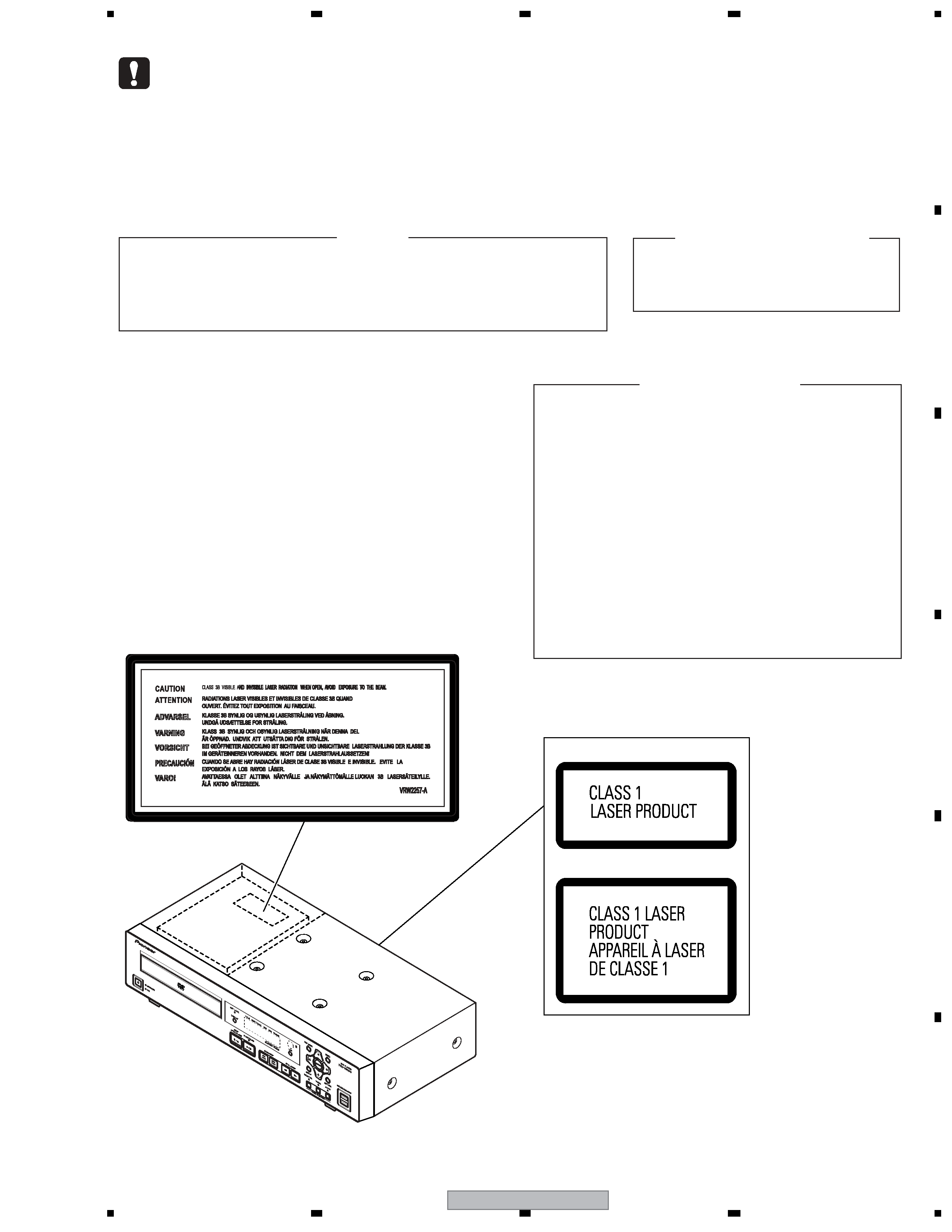
WARNING !
THE AEL (ACCESSIBLE EMISSION LEVEL) OF THE LASER POWER OUTPUT IS LESS THAN
CLASS 1 BUT THE LASER COMPONENT IS CAPABLE OF EMITTING RADIATION EXCEEDING
THE LIMIT FOR CLASS 1.
A SPECIALLY INSTRUCTED PERSON SHOULD DO SERVICING OPERATION OF THE
APPARATUS.
LASER DIODE CHARACTERISTICS
FOR DVD : MAXIMUM OUTPUT POWER : 5 mW
WAVELENGTH : 650 nm
FOR CD :
MAXIMUM OUTPUT POWER : 7 mW
WAVELENGTH : 780 nm
LABEL CHECK
(Printed on the Rear Panel)
Additional Laser Caution
: See page 87.
1. Loading-status detection switch (S101 on the LOAB assy) are detected
by the microprocessor (IC601 in the DVDM assy).
· To permit the laser diode to oscillate, it is required to set the loading-
status detection switch for the clamp position (the center terminal of
S101 is shorted to +3V).
When the voltage of IC101-pin 21 is +3V, IC601 (microprocessor)
-pin 83 is +3V and IC601-pin 84 is +3V, 650nm laser diode for DVD
oscillates in the DVDM Assy.
When the voltage of IC101-pin 21 is +3V, IC601 (microprocessor)
-pin 83 is 0V (GND) and IC601-pin 84 is +3V, 780nm laser diode for
CD oscillates in the DVDM Assy.
In the test mode * , the laser diode oscillates when microprocessor
detects a PLAY signal, or when the PLAY key is pressed (S9043 ON in
the KEYB assy), with the above requirements satisfied.
2. When the cover is open, close viewing through the objective lens with
the naked eye will cause exposure to the laser beam.
This service manual is intended for qualified service technicians ; it is not meant for the casual do-it-
yourselfer. Qualified technicians have the necessary test equipment and tools, and have been trained
to properly and safely repair complex products such as those covered by this manual.
Improperly performed repairs can adversely affect the safety and reliability of the product and may
void the warranty. If you are not qualified to perform the repair of this product properly and safely, you
should not risk trying to do so and refer the repair to a qualified service technician.
WYXJ5
KUCXJ
DVD-V8000
4
1234
123
4
C
D
F
A
B
E
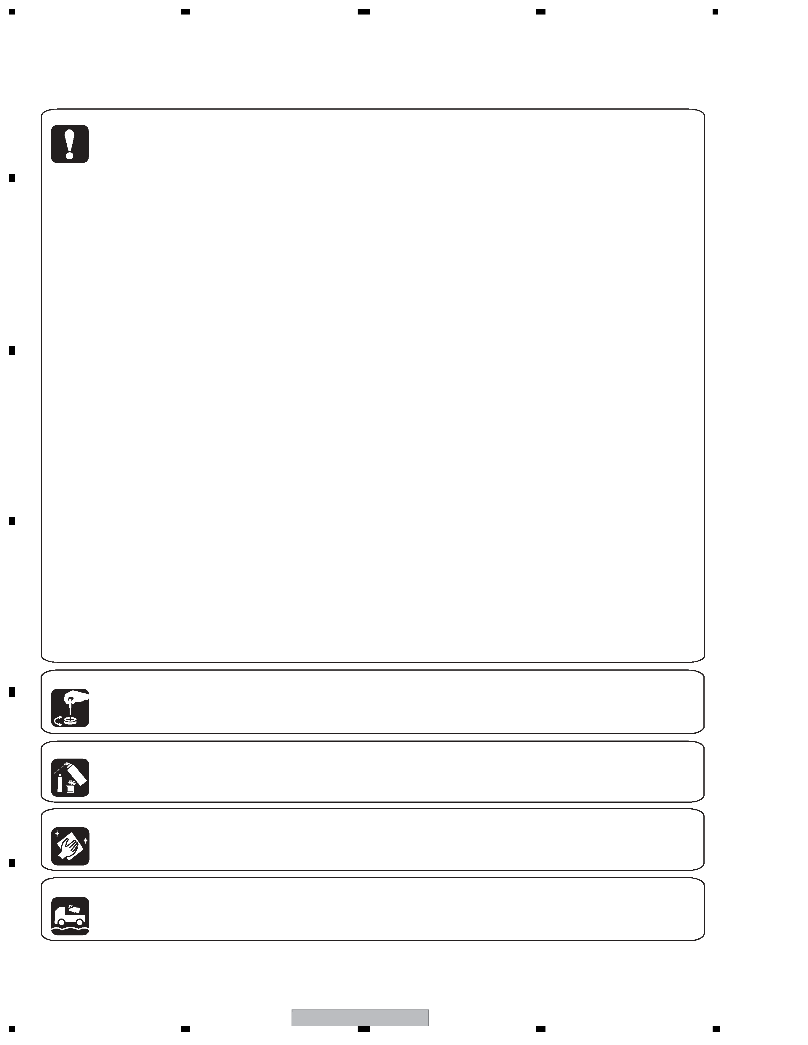
[Important Check Points for Good Servicing]
In this manual, procedures that must be performed during repairs are marked with the below symbol.
Please be sure to confirm and follow these procedures.
1. Product safety
Please conform to product regulations (such as safety and radiation regulations), and maintain a safe servicing environment by
following the safety instructions described in this manual.
1 Use specified parts for repair.
Use genuine parts. Be sure to use important parts for safety.
2 Do not perform modifications without proper instructions.
Please follow the specified safety methods when modification(addition/change of parts) is required due to interferences such as
radio/TV interference and foreign noise.
3 Make sure the soldering of repaired locations is properly performed.
When you solder while repairing, please be sure that there are no cold solder and other debris.
Soldering should be finished with the proper quantity. (Refer to the example)
4 Make sure the screws are tightly fastened.
Please be sure that all screws are fastened, and that there are no loose screws.
5 Make sure each connectors are correctly inserted.
Please be sure that all connectors are inserted, and that there are no imperfect insertion.
6 Make sure the wiring cables are set to their original state.
Please replace the wiring and cables to the original state after repairs.
In addition, be sure that there are no pinched wires, etc.
7 Make sure screws and soldering scraps do not remain inside the product.
Please check that neither solder debris nor screws remain inside the product.
8 There should be no semi-broken wires, scratches, melting, etc. on the coating of the power cord.
Damaged power cords may lead to fire accidents, so please be sure that there are no damages.
If you find a damaged power cord, please exchange it with a suitable one.
9 There should be no spark traces or similar marks on the power plug.
When spark traces or similar marks are found on the power supply plug, please check the connection and advise on secure
connections and suitable usage. Please exchange the power cord if necessary.
0 Safe environment should be secured during servicing.
When you perform repairs, please pay attention to static electricity, furniture, household articles, etc. in order to prevent injuries.
Please pay attention to your surroundings and repair safely.
2. Adjustments
To keep the original performance of the products, optimum adjustments and confirmation of characteristics within specification.
Adjustments should be performed in accordance with the procedures/instructions described in this manual.
4. Cleaning
For parts that require cleaning, such as optical pickups, tape deck heads, lenses and mirrors used in projection monitors, proper
cleaning should be performed to restore their performances.
3. Lubricants, Glues, and Replacement parts
Use grease and adhesives that are equal to the specified substance.
Make sure the proper amount is applied.
5. Shipping mode and Shipping screws
To protect products from damages or failures during transit, the shipping mode should be set or the shipping screws should be
installed before shipment. Please be sure to follow this method especially if it is specified in this manual.

DVD-V8000
5
5
678
56
7
8
C
D
F
A
B
E
¶ Steps to be taken during repair
The steps and care to be taken when Assys are replaced for repair or inspection are described here.
First, copy the user setting data to a USB memory device.
Before repair, inspection, or downloading of the firmware, the files indicated below must be copied to a USB memory device
just in case the user setting data are accidentally reset to default:
· SETUP menu and ADV. SETUP menu (***.set): SAVE SETUP
· Command stack (***.cmd): SAVE COMMAND STACK
The Error History must be also copied to a USB memory device. (Data on the serial number and accumulated playback
time will also be obtained.)
· Error History (***.err): SAVE ERROR LOG
For detailed operation, see the operating instructions.
When the pickup or the part that contains the pickup, such as the Traverse mechanism, is to be replaced
· For replacement, follow the procedures described in "7.6 DISASSEMBLY."
· For adjustment, follow the procedures described in "6. ADJUSTMENT."
· Perform only "How to reset playback time B" in "7.1.7."
When the POWER SUPPLY Unit is to be replaced
· Perform only "How to reset Power-on time B" in "7.1.7."
When the DVDM Assy is to be replaced
Replace the Assy, following the procedures described in "7.6 DISASSEMBLY."
· Before disconnecting the FFC cable between the Pickup Assy and the DVDM Assy (CN111), be sure to short-circuit the
short-circuiting land of the pickup with Sn-Ag-Cu alloy.
· If the AJKB Assy is to be replaced at the same time, resetting of the ID number and copying of ID data are required.
· See "7. GENERAL INFORMATION."
When the AJKB Assy is to be replaced
· Copying of ID data is required. Also, destination setting and input of the serial number are required.
· See "7. GENERAL INFORMATION."
· If the DVDM Assy is to be replaced at the same time, besides the settings mentioned above, resetting of the ID number is
also required.
· See "7. GENERAL INFORMATION."
When downloading the firmware
If you download the firmware via the RS-232C serial port after failing to upgrade it using the CD-R disc, settings, such as
SETUP, ADV.SETUP, and the command stack, are all reset to default.
· See "7. GENERAL INFORMATION."