ORDER NO.
PIONEER CORPORATION 4-1, Meguro 1-chome, Meguro-ku, Tokyo 153-8654, Japan
PIONEER ELECTRONICS SERVICE, INC. P.O. Box 1760, Long Beach, CA 90801-1760, U.S.A.
PIONEER EUROPE N.V. Haven 1087, Keetberglaan 1, 9120 Melsele, Belgium
PIONEER ELECTRONICS ASIACENTRE PTE. LTD. 253 Allexandra Road, #04-01, Singapore 159936
PIONEER CORPORATION 2000
c
RRV2269
DVD-D7362
1. SAFETY INFORMATION ....................................... 2
2. EXPLODED VIEWS AND PARTS LIST ................. 3
3. BLOCK DIAGRAM AND SCHEMATIC DIAGRAM
8
4. PCB CONNECTION DIAGRAM ........................... 20
5. PCB PARTS LIST ................................................ 24
6. ADJUSTMENT ..................................................... 26
CONTENTS
7. GENERAL INFORMATION .................................. 31
7.1 DIAGNOSIS ................................................... 31
7.1.1 DISASSEMBLY .................................... 31
7.2 PARTS ........................................................... 33
7.2.1 IC .......................................................... 33
8. PANEL FACILITIES AND SPECIFICATIONS ....... 34
T ZZY MAR. 2000 Printed in Japan
THIS MANUAL IS APPLICABLE TO THE FOLLOWING MODEL(S) AND TYPE(S).
DVD-ROM DRIVE UNIT
Remarks
Type
Model
DVD-D7362
Power Requirement
ZUCYV/WL
O
DC Power supply from other system

DVD-D7362
2
1. SAFETY INFORMATION
This service manual is intended for qualified service technicians; it is not meant for the casual
do-it-yourselfer. Qualified technicians have the necessary test equipment and tools, and have been
trained to properly and safely repair complex products such as those covered by this manual.
Improperly performed repairs can adversely affect the safety and reliability of the product and may
void the warranty. If you are not qualified to perform the repair of this product properly and safely, you
should not risk trying to do so and refer the repair to a qualified service technician.
WARNING
This product contains lead in solder and certain electrical parts contain chemicals which are known to the state of California to cause
cancer, birth defects or other reproductive harm.
Health & Safety Code Section 25249.6 Proposition 65
IMPORTANT
THIS PIONEER APPARATUS CONTAINS
LASER OF CLASS 1.
SERVICING OPERATION OF THE APPARATUS
SHOULD BE DONE BY A SPECIALLY
INSTRUCTED PERSON.
LASER DIODE CHARACTERISTICS
MAXIMUM OUTPUT POWER: 7 mw
WAVELENGTH: 640 nm (DVD) , 780 nm (CD-ROM)
1. The ON/OFF(ON:low level,OFF:high level) status of the
CLAMP signals for detcting the loading state are detected
by the drive CPUs, and the design prevents laser diode
oscillation when the CLAMP signal turns OFF.
In normal operation, if no disc is clamped, the laser diode
oscillation is disabled.
However, the interlock does not always operate in the test
mode.
*
2. When the cover is opened, close viewing of the objective
lens with the naked eye will cause exposure to a Class 1
laser beam.
Additional Laser Caution
* Refer to page 28.
DVD-D7362
3
2. EXPLODED VIEWS AND PARTS LIST
NOTES :
÷ Parts marked by " NSP " are generally unavailable because they are not in our Master Spare Parts List.
÷ The
mark found on some component parts indicates the importance of the safety factor of the part.
Therefore, when replacing, be sure to use parts of identical designation.
÷ Screw adjacent to
mark on the product are used for disassembly.
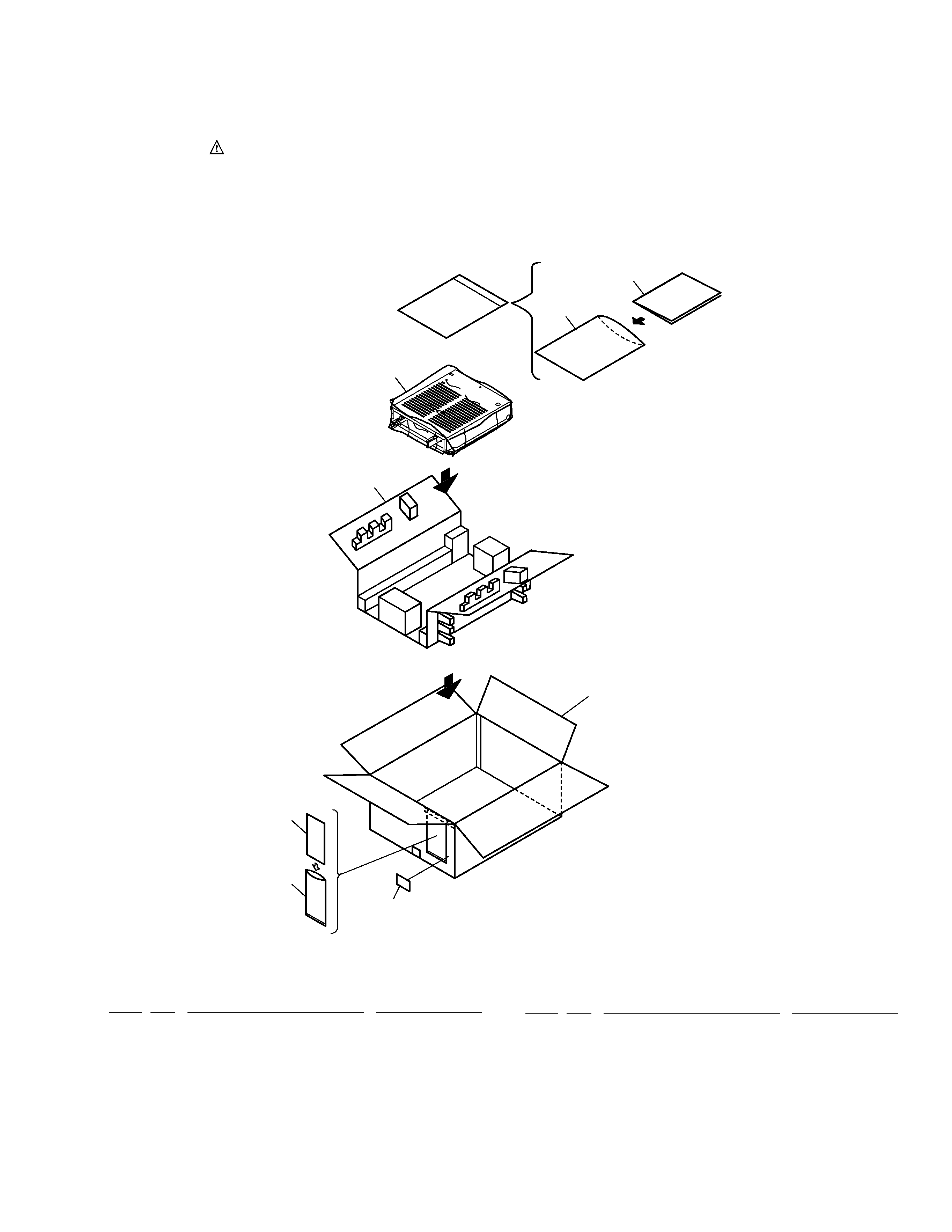
2.1 PACKING
NSP
1
Warranty Card
ARY1093
2
Operating Instructions
DRC1137
(English/ French/ German/ Japanese)
NSP
3
Polyethylene Bag
Z21-010
(100x230x0.018)
NSP
4
Polyethylene Bag
Z21-038
(230x340x0.03)
5
Pad
DHA1494
Mark No.
Description
Part No.
PARTS LIST
6
Packing Case
DHG2008
7
Bag
DHL1052
NSP
8
Label
VRW1629
Mark No.
Description
Part No.
4
2
1
3
8
6
7
5
DVD-D7362
4
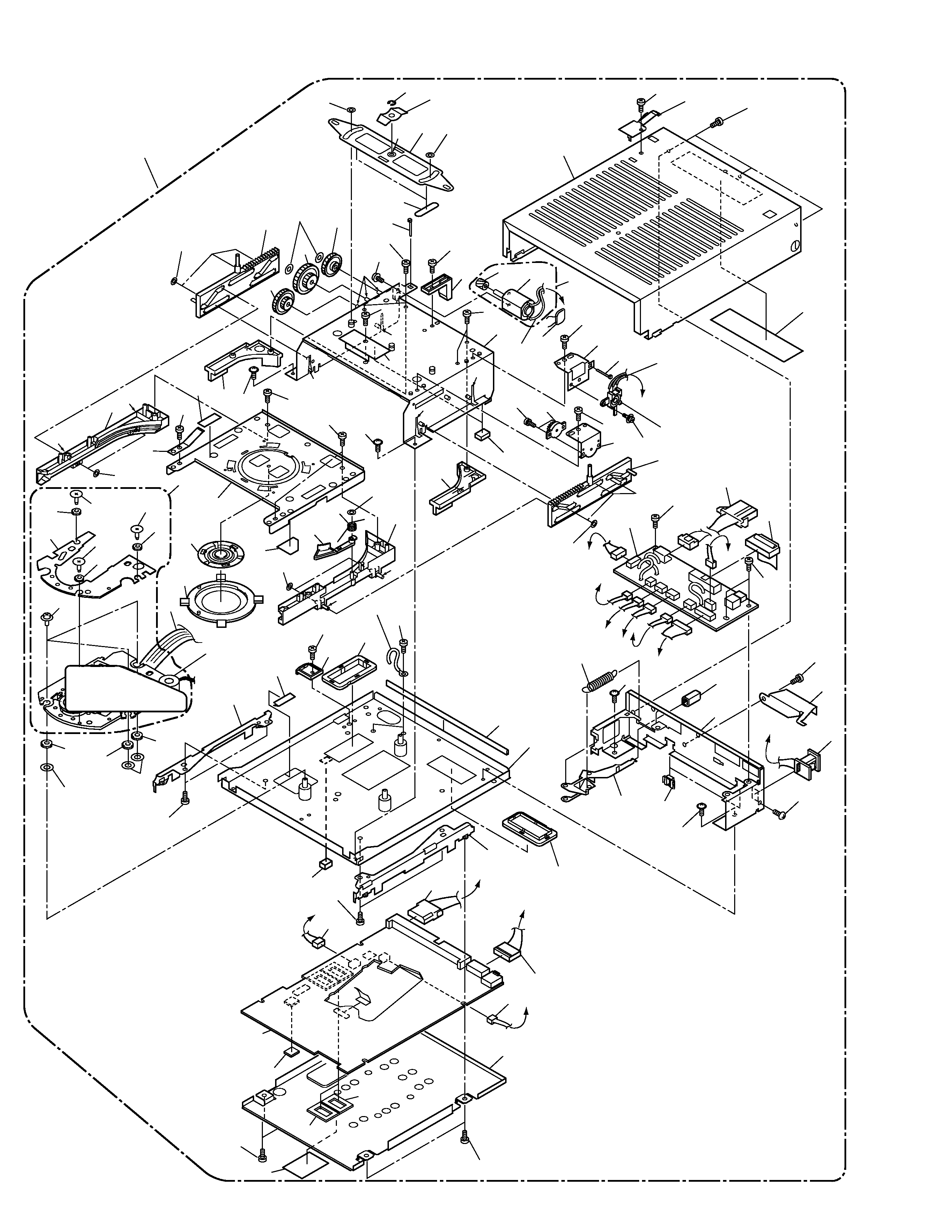
2.2 EXTERIOR
G
A
F
C
D
A
B
B
C
D
E
E
F
G
27
85
73
73
16
26
31
71
79
44
45
64
63
41
71
57
11
71
37
39
93
48
90
48
39
89
48
89
89
63
75
42
72
32
73
40
71
23
77
71
38
71
19
33
83
84
71
59
61
63
55
3
78
66
58
91
54
10
65
53
71
60
66
6
2
71
80
7
5
67
4
14
24
87
56
80
34
29
80
33
30 63
81
25
81
17
63
46
92
83
28
20
70
73
76
82
63
73
18
41
35
36
80
21
43
52
52
12
47
47
15
22
9
1
49
50
50
51
8
74
74
80
Refer to
2.3 TRAVERSE
MECHANISM ASSY
47
*
*
*
*
*
*
*
*
*
*
* :Froil (PN-397)

DVD-D7362
5
1
MAIN BOARD ASSY
DWX2038
2
RIFB BOARD ASSY
DWX1960
3
IDSB BOARD ASSY
DWS1297
4
Capacitor (C1)
CFTLA224J50
5
Connector Assy
DKP3281
6
Connector Assy
DKP3456
7
Connector Assy
DKP3471
8
Connector Assy
DKP3484
9
Connector Assy
DKP3486
10
Connector Assy
DKP3488
11
Connector Assy
DKP3487
NSP
12
P.U Flexible Wire 26P
DNP1917
13
· · · · ·
14
Connector Assy
PF02PY-B15
NSP
15
Traverse Mechanism Assy
DXB1725
16
Disc Holder Spring
DBH1342
17
Spring
DBK1134
18
EarTH Plate
DBK1139
19
Cushion
DEB1355
20
Slide Sheet
DEC2034
21
Disc Holder Sheet
DEC2203
22
Clamper Stay S
DND1206
23
Switch Bracket
DNF1539
24
Clamper Base
DNH2283
25
Joint Arm
DNH2284
26
CL Disc Holder
DNK3253
27
Motor Gear
DNK3254
28
CL Gear (B)
DNK3256
29
CL Gear (C)
DNK3257
30
Disc Holder (L)
DNK3289
31
Disc Holder (R)
DNK3290
32
Disc Stopper
DNK3291
33
Rack Plate
DNK3292
34
CL Gear (A)
DNK3363
35
Side Rack (L)
DNK3364
36
Side Rack (R)
DNK3365
37
Clamper Bracket D3
DNK3688
38
Lever Switch
DSK1003
39
Clamper 98 AssY
DXA1859
40
Motor
PXM1002
41
Tape (G)
REH1010
42
Damper Assy
VXA1153
43
Floating Screw
DBA1072
44
PL Lock Spring
DBH1447
45
PL Lock Arm
DBK1187
Mark No.
Description
Part No.
46
PL Earth Plate
DBK1174
47
Floating Rubber D3
DEB1404
NSP
48
DRA Screw
DBA1131
NSP
49
Silicon Rubber DS
DEB1446
NSP
50
Silicon Sheet
DEB1458
NSP
51
Silicon Sheet
DEB1460
52
Washer
DEC2213
NSP
53
Player Base D3
DNA1246
54
Bottom Plate
DNF1654
55
PL Rear Panel
DNC1507
56
PL Upper Cover
DNE1372
57
PL Angle DVD L
DNF1590
58
PL Angle DVD R
DNF1591
59
PL Grip
DNH2399
60
PL Rail
DNK3665
61
PL Lock Cap
DNK3667
62
· · · · ·
63
Screw
DBA1133
NSP
64
Edge Sadle
DEC1807
65
Tape
DED1141
66
Protector V2
DNK3393
67
65 Label
ARW7050
68
Screw
BBT30P060FZK
69
· · · · ·
70
Screw
BBZ30P040FNI
71
Screw
BBZ30P060FMC
72
Screw
BBZ30P080FZK
73
Screw
BPZ30P080FCU
74
Screw
DBA1136
75
Screw
PMA20P050FMC
76
Screw
PMH20P040FMC
77
Screw
PMH26P060FMC
78
Screw
TBZ40P060FMC
79
Cord Clamper
RNH-184
80
Washer
WT26D047D050
81
Washer
WT36D072D050
82
Ering
YE30FUC
83
Binder
ZCA-SKB90BK
84
Damper Braket
DNF1541
85
Clamp Motor Assy-S
DXX2336
86
· · · · ·
87
Sheet
DED1143
88
· · · · ·
NSP
89
DRA Rubber
DEB1429
NSP
90
DRA Weight
DNH2429
91
Spacer
REB1179
92
DVD-ROM DRIVE-S
DXX2476
93
G4 Servo Mechanism Assy
DXX2480
(for Service)
Mark No.
Description
Part No.
EXTERIOR PARTS LIST