ORDER NO.
PIONEER CORPORATION 4-1, Meguro 1-chome, Meguro-ku, Tokyo 153-8654, Japan
PIONEER ELECTRONICS SERVICE, INC. P.O. Box 1760, Long Beach, CA 90801-1760, U.S.A.
PIONEER EUROPE NV Haven 1087, Keetberglaan 1, 9120 Melsele, Belgium
PIONEER ELECTRONICS ASIACENTRE PTE. LTD. 253 Alexandra Road, #04-01, Singapore 159936
PIONEER CORPORATION 2000
c
DV-C503
RRV2297
T IZE JULY 2000 Printed in Japan
DVD PLAYER
1. SAFETY INFORMATION ....................................... 2
2. EXPLODED VIEWS AND PARTS LIST ................. 3
3. BLOCK DIAGRAM AND SCHEMATIC DIAGRAM ... 10
4. PCB CONNECTION DIAGRAM ........................... 31
5. PCB PARTS LIST ................................................ 44
6. ADJUSTMENT ..................................................... 48
CONTENTS
7. GENERAL INFORMATION ................................ 49
7.1 DIAGNOSIS .................................................. 49
7.1.1 SELF-DIAGNOSTIC FUNCTION OF
PICKUP DEFECTIVE ........................... 49
7.1.2 TEST POINTS LOCATION ................... 50
7.1.3 TEST MODE SCREEN DISPLAY ........ 51
7.1.4 ERROR CODE ..................................... 55
7.1.5 DISASSEMBLY .................................... 59
7.1.6 TROUBLE SHOOTING
FOR MECHANISM SECTION .............. 71
7.1.7 TROUBLE SHOOTING
FOR ELECTRICAL SECTION .............. 74
7.2 PARTS .......................................................... 75
7.2.1 IC .......................................................... 75
7.2.2 FL DISPLAY ......................................... 88
8. PANEL FACILITIES AND SPECIFICATIONS .... 89
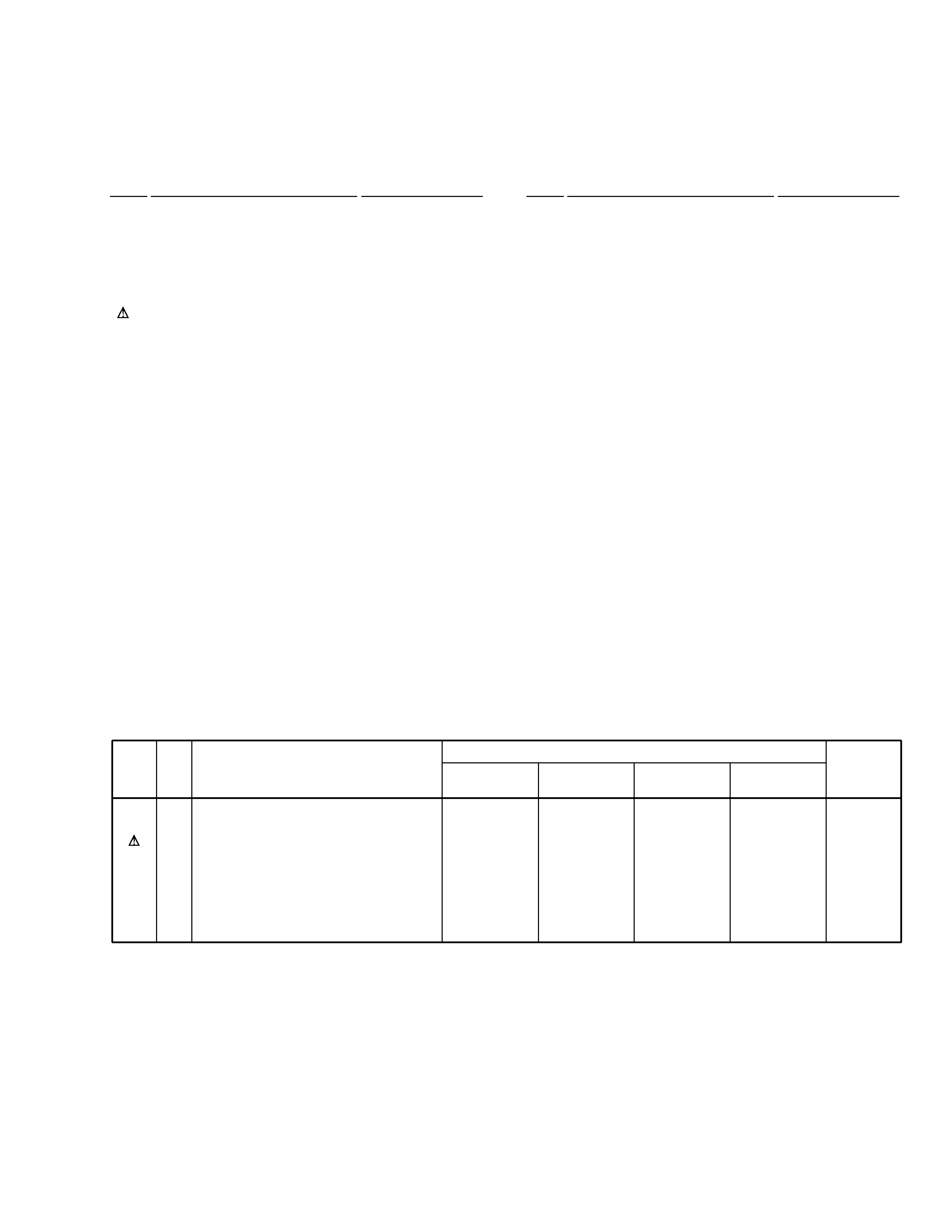
THIS MANUAL IS APPLICABLE TO THE FOLLOWING MODEL(S) AND TYPE(S).
Type
Model
Power Requirement
Region No.
Remarks
DV-C503
KUXQ
AC120V
1
KCXQ
AC120V
1
RDXQ1/RA
AC110-127 / 220-240V
1
RDXQ/RD
AC110-127 / 220-240V
4
DVD PLAYER
STANDBY/ON
CD MODE
RANDOM
73
8
DISC SKIP
0 OPEN/CLOSE
EXCHANGE
DISC
12
3
4
5
2
DV-C503
1. SAFETY INFORMATION
This service manual is intended for qualified service technicians ; it is not meant for the casual do-it-
yourselfer. Qualified technicians have the necessary test equipment and tools, and have been trained
to properly and safely repair complex products such as those covered by this manual.
Improperly performed repairs can adversely affect the safety and reliability of the product and may
void the warranty. If you are not qualified to perform the repair of this product properly and safely, you
should not risk trying to do so and refer the repair to a qualified service technician.
WARNING
This product contains lead in solder and certain electrical parts contain chemicals which are known to the state of California to cause
cancer, birth defects or other reproductive harm.
Health & Safety Code Section 25249.6 Proposition 65
NOTICE
(FOR CANADIAN MODEL ONLY)
Fuse symbols
(fast operating fuse) and/or
(slow operating fuse) on PCB indicate that replacement parts must
be of identical designation.
REMARQUE
(POUR MODÈLE CANADIEN SEULEMENT)
Les symboles de fusible
(fusible de type rapide) et/ou
(fusible de type lent) sur CCI indiquent que les pièces
de remplacement doivent avoir la même désignation.
ANY MEASUREMENTS NOT WITHIN THE LIMITS
OUTLINED ABOVE ARE INDICATIVE OF A POTENTIAL
SHOCK HAZARD AND MUST BE CORRECTED BEFORE
RETURNING THE APPLIANCE TO THE CUSTOMER.
2. PRODUCT SAFETY NOTICE
Many electrical and mechanical parts in the appliance
have special safety related characteristics. These are
often not evident from visual inspection nor the protection
afforded by them necessarily can be obtained by using
replacement components rated for voltage, wattage, etc.
Replacement parts which have these special safety
characteristics are identified in this Service Manual.
Electrical components having such features are identified
by marking with a
on the schematics and on the parts list
in this Service Manual.
The use of a substitute replacement component which does
not have the same safety characteristics as the PIONEER
recommended replacement one, shown in the parts list in
this Service Manual, may create shock, fire, or other hazards.
Product Safety is continuously under review and new
instructions are issued from time to time. For the latest
information, always consult the current PIONEER Service
Manual. A subscription to, or additional copies of, PIONEER
Service Manual may be obtained at a nominal charge from
PIONEER.
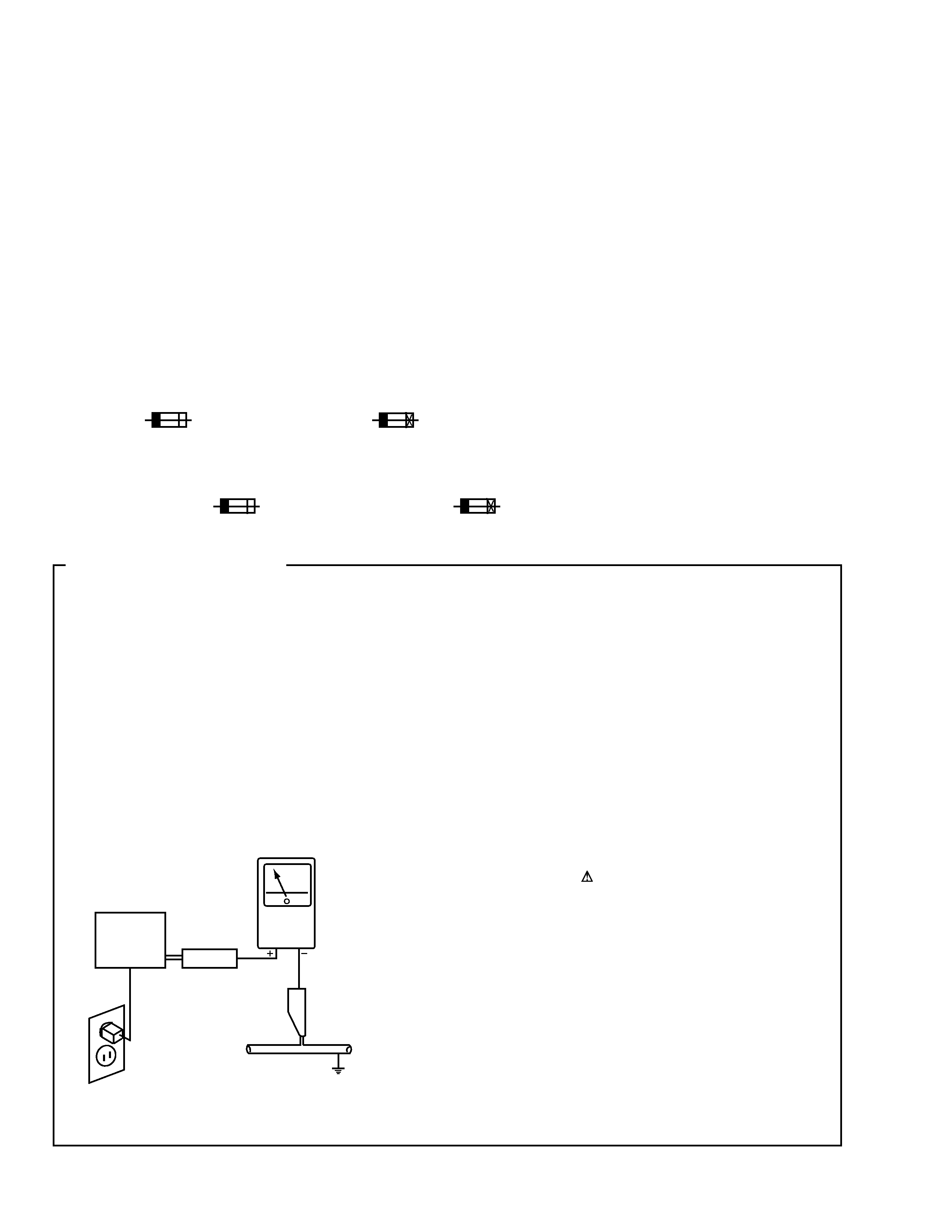
1. SAFETY PRECAUTIONS
The following check should be performed for the
continued protection of the customer and service
technician.
LEAKAGE CURRENT CHECK
Measure leakage current to a known earth ground (water
pipe, conduit, etc.) by connecting a leakage current tester
such as Simpson Model 229-2 or equivalent between the
earth ground and all exposed metal parts of the appliance
(input/output terminals, screwheads, metal overlays, control
shaft, etc.). Plug the AC line cord of the appliance directly
into a 120V AC 60Hz outlet and turn the AC power switch
on. Any current measured must not exceed 0.5mA.
(FOR USA MODEL ONLY)
Leakage
current
tester
Reading should
not be above
0.5mA
Device
under
test
Test all
exposed metal
surfaces
Also test with
plug reversed
(Using AC adapter
plug as required)
Earth
ground
AC Leakage Test
3
DV-C503
FRONT
12
5
13
KCXQ Type Only
Except
RDXQ/RD Type
14
RDXQ/RD Type
Only
15
4
6
11
11
3
2
1
8
9
7
10
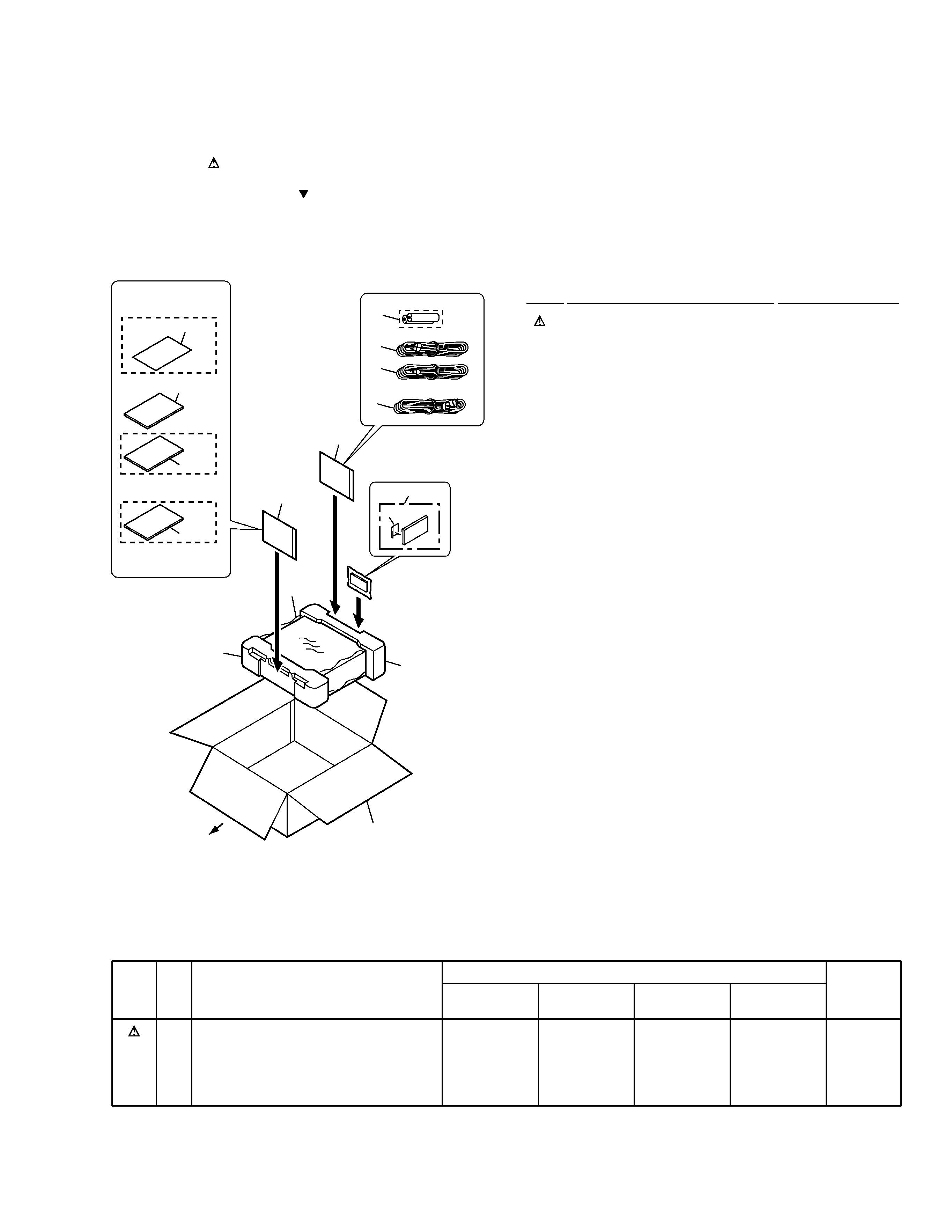
2.1 PACKING
(1) PACKING PARTS LIST
Mark No.
Description
Part No.
2. EXPLODED VIEWS AND PARTS LIST
NOTES:
· Parts marked by "NSP" are generally unavailable because they are not in our Master Spare Parts List.
· The mark found on some component parts indicates the importance of the safety factor of the part.
Therefore, when replacing, be sure to use parts of identical designation.
· Screws adjacent to mark on the product are used for disassembly.
(2) CONTRAST TABLE
DV-C503/KUXQ, KCXQ, RDXQ1/RA and RDXQ/RD are constructed the same except for the following :
Mark No.
Symbol and Description
Part No.
Remarks
KUXQ
Type
KCXQ
Type
RDXQ1/RA
Type
RDXQ/RD
Type
NSP
1
9
12
14
15
Power Cord
Packing Case
Warranty Card
Operating Instructions (French)
Operating Instructions (Spanish/Portuguese)
ADG7022
VHG1895
ARY7045
Not used
Not used
ADG7022
VHG1951
ARY7045
VRC1117
Not used
ADG1158
VHG1918
ARY7025
Not used
Not used
ADG1158
VHG1919
Not used
Not used
VRD1110
1
Power Cord
See Contrast table (2)
2
Audio Cord (L = 1.5m)
VDE1054
3
Video Cord (L = 1.5m)
VDE1055
4
Remote Control Unit
VXX2705
5
Battery Cover
AZA7204
NSP
6
Dry Cell Battery (R6P, AA)
VEM1010
7
Pad F
VHA1247
8
Pad R
VHA1248
9
Packing Case
See Contrast table (2)
10
Sheet
RHX1006
11
Polyethylene Bag
VHL1051
NSP
12
Warranty Card
See Contrast table (2)
13
Operating Instructions (English) VRB1243
14
Operating Instructions (French) See Contrast table (2)
15
Operating Instructions
See Contrast table (2)
(Spanish/Portuguese)
4
DV-C503
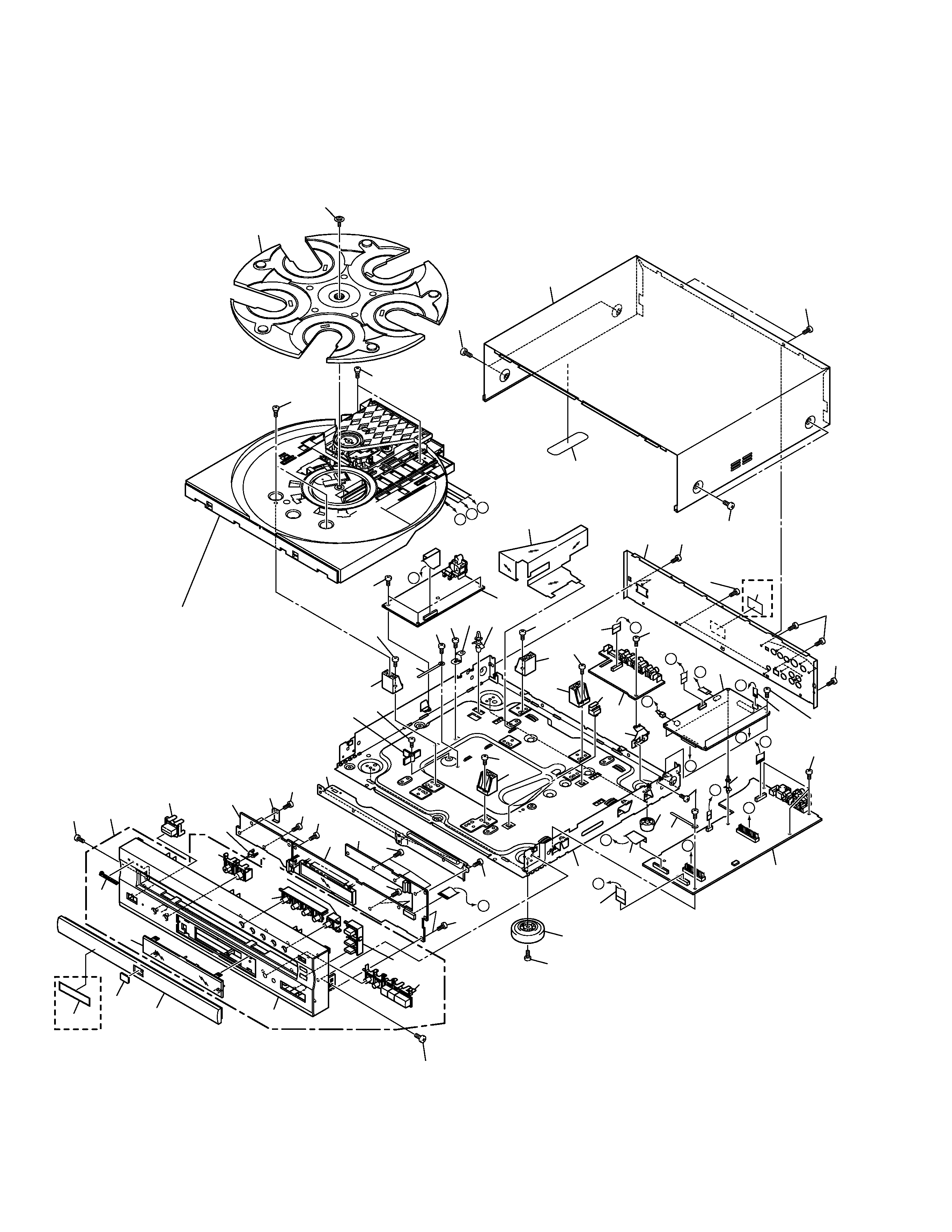
2.2 EXTERIOR
A
A
B
F
F
C
D
I
H
G
E
E
D
C
B
H
I
G
26
43
46
49
49
46
45
45
45
45
45
16
45
45
45
RDXQ1/RA,
RDXQ/RD
Types Only
23
1
9
20
24
18
18
5
4
6
19
30
31
32
42
33
44
44
13
17
21
51
45
50
50
50
50
50
50
50
10
22
14
45
8
15
27
27
27
28
27
3
7
2
11
39
45
Refer to
"2.3 TABLE MECHANISM SECTION".
40
Except
KCXQ Type
48
25
48
48
36
(1/3)
36
(3/3)
36
(2/3)
38
(1/2)
38
(2/2)
48
48
48
48
29
37
34
35
5
DV-C503
(1) EXTERIOR PARTS LIST
Mark No.
Description
Part No.
(2) CONTRAST TABLE
DV-C503/KUXQ, KCXQ, RDXQ1/RA and RDXQ/RD are constructed the same except for the following :
Mark No.
Symbol and Description
Part No.
Remarks
KUXQ
Type
KCXQ
Type
RDXQ1/RA
Type
RDXQ/RD
Type
NSP
2
4
7
23
33
35
40
42
JAC1 Assy
FLKY Assy
POWER SUPPLY Unit
Rear Panel
Front Panel Assy
Front Panel
Label
Getter
VWV1751
VWG2182
VWR1329
VNA2168
VXA2410
VNK4602
Not used
VRW1819
VWV1751
VWG2182
VWR1329
VNA2168
VXA2410
VNK4602
Not used
Not used
VWV1753
VWG2183
VWR1332
VNA2199
VXA2413
VNK4655
VRW1699
VRW1819
VWV1753
VWG2183
VWR1332
VNA2250
VXA2413
VNK4655
VRW1699
VRW1819
1
DVDM Assy
VWS1429
2
JAC1 Assy
See Contrast table (2)
3
JAC2 Assy
VWV1752
4
FLKY Assy
See Contrast table (2)
NSP
5
KYLB Assy
VWG2186
NSP
6
PWSB Assy
VWG2188
7
POWER SUPPLY Unit
See Contrast table (2)
8
Flexible Cable (26P)
VDA1825
9
Flexible Cable (16P)
VDA1826
10
Flexible Cabe (15P)
VDA1827
11
Flexible Cable (07P)
VDA1828
12
· · · · ·
NSP
13
PCB Holder
PNW2100
14
Insulator
PNW2766
15
Foot Assy
REC1263
NSP
16
PCB Support
REC1285
NSP
17
PCB Base
RNE1221
18
Cord Clamper
RNH-184
19
Earth Plate
VBK1121
20
PCB Hinge
VEC1174
21
Barrier
VEC2176
NSP
22
Base Chassis
VNA2167
23
Rear Panel
See Contrast table (2)
NSP
24
JB Stay
VNE2223
25
FP Angle
VNE2233
Mark No.
Description
Part No.
26
Rotary Tray
VNK4739
27
Mechanism Holder
VNL1869
28
Mechanism Support
VNL1906
29
DVD Badge
VAM1102
30
PW Button
VNK4101
31
LED Lens
VNK4503
32
Tray Panel
VNK4604
33
Front Panel Assy
See Contrast table (2)
34
Pioneer Badge
VAM1109
35
Front Panel
See Contrast table (2)
36
Main Key
VNK4603
37
FL Lens
VNK4617
38
5 Key
VNK4643
39
Bonnet S
VXX2728
40
Label
See Contrast table (2)
41
· · · · ·
NSP
42
Getter
See Contrast table (2)
NSP
43
TS Screw
DBA1006
44
Screw
IBZ30P080FMC
45
Screw
BBZ30P080FMC
46
Screw
BCZ40P060FZK
47
Screw
IBZ30P080FMC
48
Screw
BBZ30P100FZK
49
Screw
VBA1079
50
Screw
BBZ30P060FZK
NSP
51
Large Label
VRW1855