ORDER NO.
PIONEER CORPORATION 4-1, Meguro 1-chome, Meguro-ku, Tokyo 153-8654, Japan
PIONEER ELECTRONICS (USA) INC. P.O. Box 1760, Long Beach, CA 90801-1760, U.S.A.
PIONEER EUROPE NV Haven 1087, Keetberglaan 1, 9120 Melsele, Belgium
PIONEER ELECTRONICS ASIACENTRE PTE. LTD. 253 Alexandra Road, #04-01, Singapore 159936
PIONEER CORPORATION 2005
DV-989AVi-S
RRV3271
DVD PLAYER
DV-989AVi-S
DV-989AVi-G
THIS MANUAL IS APPLICABLE TO THE FOLLOWING MODEL(S) AND TYPE(S).
Model
Type
Power Requirement
Region No.
Remarks
DV-989AVi-S
WYXJ
AC220240V
2
DV-989AVi-S
YXJRE
AC220240V
5
DV-989AVi-G
HLXJ
AC220-240V
3
DV-989AVi-S
WPWXJ
AC220240V
4
For details, refer to "Important symbols for good services".
T-ZZR OCT. 2005 printed in Japan
DV-989AVi-S
2
1234
123
4
C
D
F
A
B
E
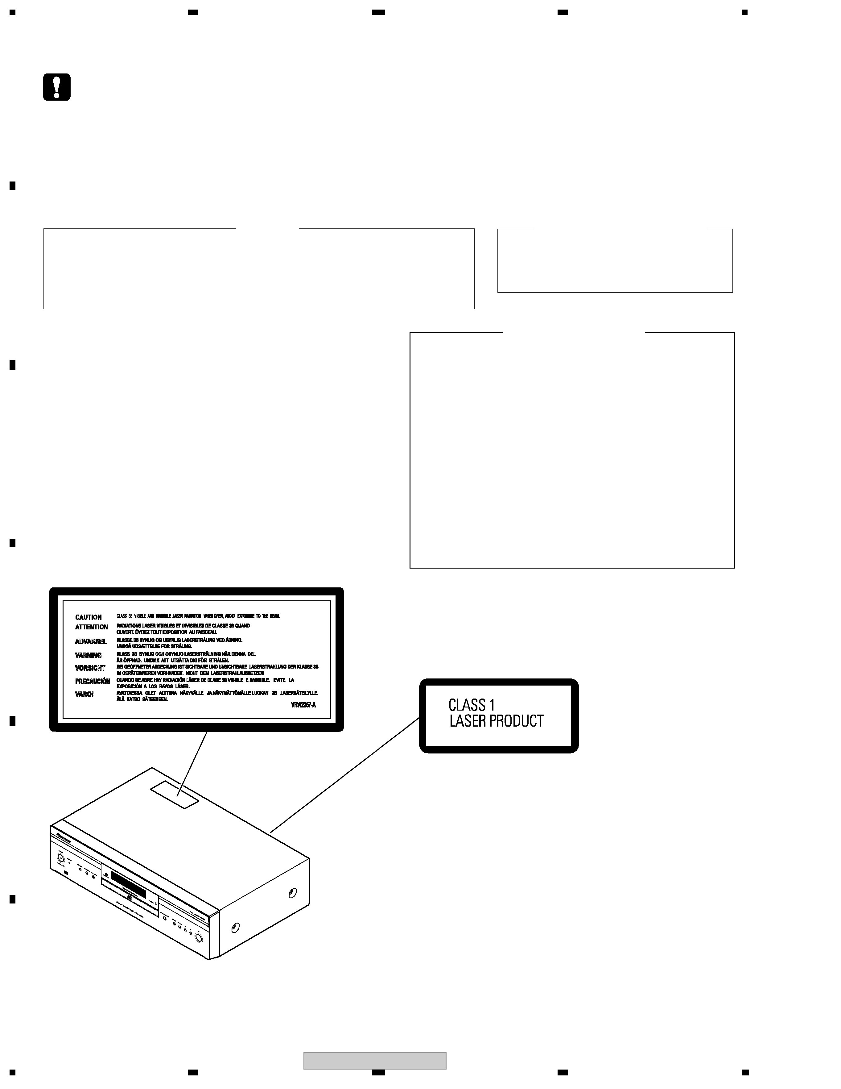
SAFETY INFORMATION
WARNING !
THE AEL (ACCESSIBLE EMISSION LEVEL) OF THE LASER POWER OUTPUT IS LESS THAN
CLASS 1 BUT THE LASER COMPONENT IS CAPABLE OF EMITTING RADIATION EXCEEDING
THE LIMIT FOR CLASS 1.
A SPECIALLY INSTRUCTED PERSON SHOULD DO SERVICING OPERATION OF THE
APPARATUS.
LASER DIODE CHARACTERISTICS
FOR DVD : MAXIMUM OUTPUT POWER : 5 mW
WAVELENGTH : 650 nm
FOR CD :
MAXIMUM OUTPUT POWER : 5 mW
WAVELENGTH : 780 nm
LABEL CHECK
(Printed on the Rear Panel)
Additional Laser Caution
: See page 87.
1. Loading-status detection switch (S101 on the LOAB assy) are detected
by the microprocessor (IC601 in the DVDM assy).
· To permit the laser diode to oscillate, it is required to set the loading-
status detection switch for the clamp position (the center terminal of
S101 is shorted to +3V).
When the voltage of IC101-pin 21 is +3V, IC601 (microprocessor)
-pin 83 is +3V and IC601-pin 84 is +3V, 650nm laser diode for DVD
oscillates in the DVDM Assy.
When the voltage of IC101-pin 21 is +3V, IC601 (microprocessor)
-pin 83 is 0V (GND) and IC601-pin 84 is +3V, 780nm laser diode for
CD oscillates in the DVDM Assy.
In the test mode * , the laser diode oscillates when microprocessor
detects a PLAY signal, or when the PLAY key is pressed (S104 ON in
the FLKY assy), with the above requirements satisfied.
2. When the cover is open, close viewing through the objective lens with
the naked eye will cause exposure to the laser beam.
This service manual is intended for qualified service technicians ; it is not meant for the casual do-it-
yourselfer. Qualified technicians have the necessary test equipment and tools, and have been trained
to properly and safely repair complex products such as those covered by this manual.
Improperly performed repairs can adversely affect the safety and reliability of the product and may
void the warranty. If you are not qualified to perform the repair of this product properly and safely, you
should not risk trying to do so and refer the repair to a qualified service technician.
DV-989AVi-S
3
5
678
56
7
8
C
D
F
A
B
E
[Important Check Points for Good Servicing]
In this manual, procedures that must be performed during repairs are marked with the below symbol.
Please be sure to confirm and follow these procedures.
1. Product safety
Please conform to product regulations (such as safety and radiation regulations), and maintain a safe servicing environment by
following the safety instructions described in this manual.
1 Use specified parts for repair.
Use genuine parts. Be sure to use important parts for safety.
2 Do not perform modifications without proper instructions.
Please follow the specified safety methods when modification(addition/change of parts) is required due to interferences such as
radio/TV interference and foreign noise.
3 Make sure the soldering of repaired locations is properly performed.
When you solder while repairing, please be sure that there are no cold solder and other debris.
Soldering should be finished with the proper quantity. (Refer to the example)
4 Make sure the screws are tightly fastened.
Please be sure that all screws are fastened, and that there are no loose screws.
5 Make sure each connectors are correctly inserted.
Please be sure that all connectors are inserted, and that there are no imperfect insertion.
6 Make sure the wiring cables are set to their original state.
Please replace the wiring and cables to the original state after repairs.
In addition, be sure that there are no pinched wires, etc.
7 Make sure screws and soldering scraps do not remain inside the product.
Please check that neither solder debris nor screws remain inside the product.
8 There should be no semi-broken wires, scratches, melting, etc. on the coating of the power cord.
Damaged power cords may lead to fire accidents, so please be sure that there are no damages.
If you find a damaged power cord, please exchange it with a suitable one.
9 There should be no spark traces or similar marks on the power plug.
When spark traces or similar marks are found on the power supply plug, please check the connection and advise on secure
connections and suitable usage. Please exchange the power cord if necessary.
0 Safe environment should be secured during servicing.
When you perform repairs, please pay attention to static electricity, furniture, household articles, etc. in order to prevent injuries.
Please pay attention to your surroundings and repair safely.
2. Adjustments
To keep the original performance of the products, optimum adjustments and confirmation of characteristics within specification.
Adjustments should be performed in accordance with the procedures/instructions described in this manual.
4. Cleaning
For parts that require cleaning, such as optical pickups, tape deck heads, lenses and mirrors used in projection monitors, proper
cleaning should be performed to restore their performances.
3. Lubricants, Glues, and Replacement parts
Use grease and adhesives that are equal to the specified substance.
Make sure the proper amount is applied.
5. Shipping mode and Shipping screws
To protect products from damages or failures during transit, the shipping mode should be set or the shipping screws should be
installed before shipment. Please be sure to follow this method especially if it is specified in this manual.

DV-989AVi-S
4
1234
123
4
C
D
F
A
B
E
CONTENTS
SAFETY INFORMATION ..................................................................................................................................... 2
1. SPECIFICATIONS ............................................................................................................................................ 5
2. EXPLODED VIEWS AND PARTS LIST ............................................................................................................ 6
2.1 PACKING ................................................................................................................................................... 6
2.2 EXTERIOR SECTION................................................................................................................................ 8
2.3 FRONT PANEL SECTION ....................................................................................................................... 10
2.4 LOAD
MECHA. ASSY.......................................................................................................................... 12
2.5 TRAVERSE MECHA. ASSY-S ................................................................................................................. 14
3. BLOCK DIAGRAM AND SCHEMATIC DIAGRAM ..........................................................................................16
3.1 OVERAL BLOCK DIAGRAM.................................................................................................................... 16
3.2 LOAB ASSY and OVERALL WIRING DIAGRAM..................................................................................... 18
3.3 DVDM ASSY 1/6 [FTS BLOCK] ............................................................................................................... 20
3.4 DVDM ASSY 2/6 [FR BLOCK] ................................................................................................................. 22
3.5 DVDM ASSY 3/6 [EBY/AV1 BLOCK] ....................................................................................................... 24
3.6 DVDM ASSY 4/6 [i.LINK BLOCK] ............................................................................................................ 26
3.7 DVDM ASSY 5/6 [VIDEO BLOCK]........................................................................................................... 28
3.8 DVDM ASSY 6/6 [A-DSP/AQE/SACD BLOCK]........................................................................................30
3.9 AJKB ASSY ............................................................................................................................................. 32
3.10 VJKB ASSY............................................................................................................................................ 34
3.11 FLKY, KEYB and MSWB ASSYS........................................................................................................... 36
3.12 SCRB ASSY (WYXJ5, YXJRE5 Only) ................................................................................................... 38
3.13 POWER SUPPLY UNIT.......................................................................................................................... 40
3.14 WAVEFORMS ........................................................................................................................................ 42
4. PCB CONNECTION DIAGRAM ..................................................................................................................... 45
4.1 LOAB ASSY ............................................................................................................................................. 45
4.2 DVDM ASSY ............................................................................................................................................ 46
4.3 AJKB ASSY ............................................................................................................................................. 50
4.4 VJKB ASSY.............................................................................................................................................. 52
4.5 FLKY and KEYB ASSYS ......................................................................................................................... 54
4.6 SCRB ASSY ............................................................................................................................................ 58
4.7 PS ASSY.................................................................................................................................................. 60
4.8 POWER SUPPLY UNIT............................................................................................................................ 61
5. PCB PARTS LIST ........................................................................................................................................... 62
6. ADJUSTMENT ............................................................................................................................................... 86
6.1 ADJUSTMENT ITEMS AND LOCATION ................................................................................................. 86
6.2 JIGS AND MEASURING INSTRUMENTS ............................................................................................... 86
6.3 NECESSARY ADJUSTMENT POINTS ................................................................................................... 87
6.4 TEST MODE ............................................................................................................................................ 88
6.5 MECHANISM ADJUSTMENT .................................................................................................................. 89
7. GENERAL INFORMATION ............................................................................................................................. 91
7.1 DIAGNOSIS ............................................................................................................................................. 91
7.1.1 ID NUMBER AND ID DATA SETTING ............................................................................................... 91
7.1.2 SELF-DIAGNOSIS FUNCTION OF PICKUP DEFECTIVE ............................................................... 93
7.1.3 TEST MODE SCREEN DISPLAY ...................................................................................................... 94
7.1.4 SELF-DIAGNOSIS FUNCTION ......................................................................................................... 96
7.1.5 FUNCTIONAL SPECIFICATION OF THE SERVICE MODE ............................................................. 97
7.1.6 ERROR DISPLAY .............................................................................................................................. 98
7.1.7 TROUBLE SHOOTING .................................................................................................................... 101
7.1.8 FAILURE-TEST METHOD FOR THE HDMI TRANSMITTER IC ..................................................... 103
7.1.9 SERIAL-DOWNLOAD...................................................................................................................... 104
7.1.10 DISASSEMBLY.............................................................................................................................. 105
8. PANEL FACILITIES ...................................................................................................................................... 115
DV-989AVi-S
5
5
678
56
7
8
C
D
F
A
B
E
1. SPECIFICATIONS
Specifications
General
System. . . . . . . . . . . . . . . . . . . . . . . . .DVD Player
Power requirements. . . . AC 220-240 V, 50/60 Hz
Power consumption. . . . . . . . . . . . . . . . . . . 25 W
Power consumption (standby) . . . . . . . . . . 0.3 W
Weight. . . . . . . . . . . . . . . . . . . . . . . . . . . . . 9.0 kg
Weight. . . . . . . . . . . . . . . . . (HLXJ model) 10.0 kg
Dimensions. . . . 420 (W) x 117 (H) x 340 (D) mm
Operating temperature. . . . . . . .
+5
°C to +35°C
Operating humidity . . . . . . . . . . . . . . . 5% to 85%
(no condensation)
HDMI output
HDMI output
i.LINK output
i.LINK output . . . . . . . . . . . . . . . . . . . 4 pin (S400)
Component Video output (Y, PB, PR)
Output level . . . . . . . . . . . . . . . .Y: 1.0 Vp-p (75
)
PB, PR: 0.7 Vp-p (75
)
Jacks . . . . . . . . . . . . . . . . . . . . . . . . . . .RCA jacks
S-Video output
Y (luminance) - Output level . . . . . 1 Vp-p (75
)
C (color) - Output level. . . . . . . 286 mVp-p (75
)
Jack . . . . . . . . . . . . . . . . . . . . . . . . . . S-Video jack
Video output
Output level . . . . . . . . . . . . . . . . . . 1 Vp-p (75
)
Jack. . . . . . . . . . . . . . . . . . . . . . . . . . . . .RCA jack
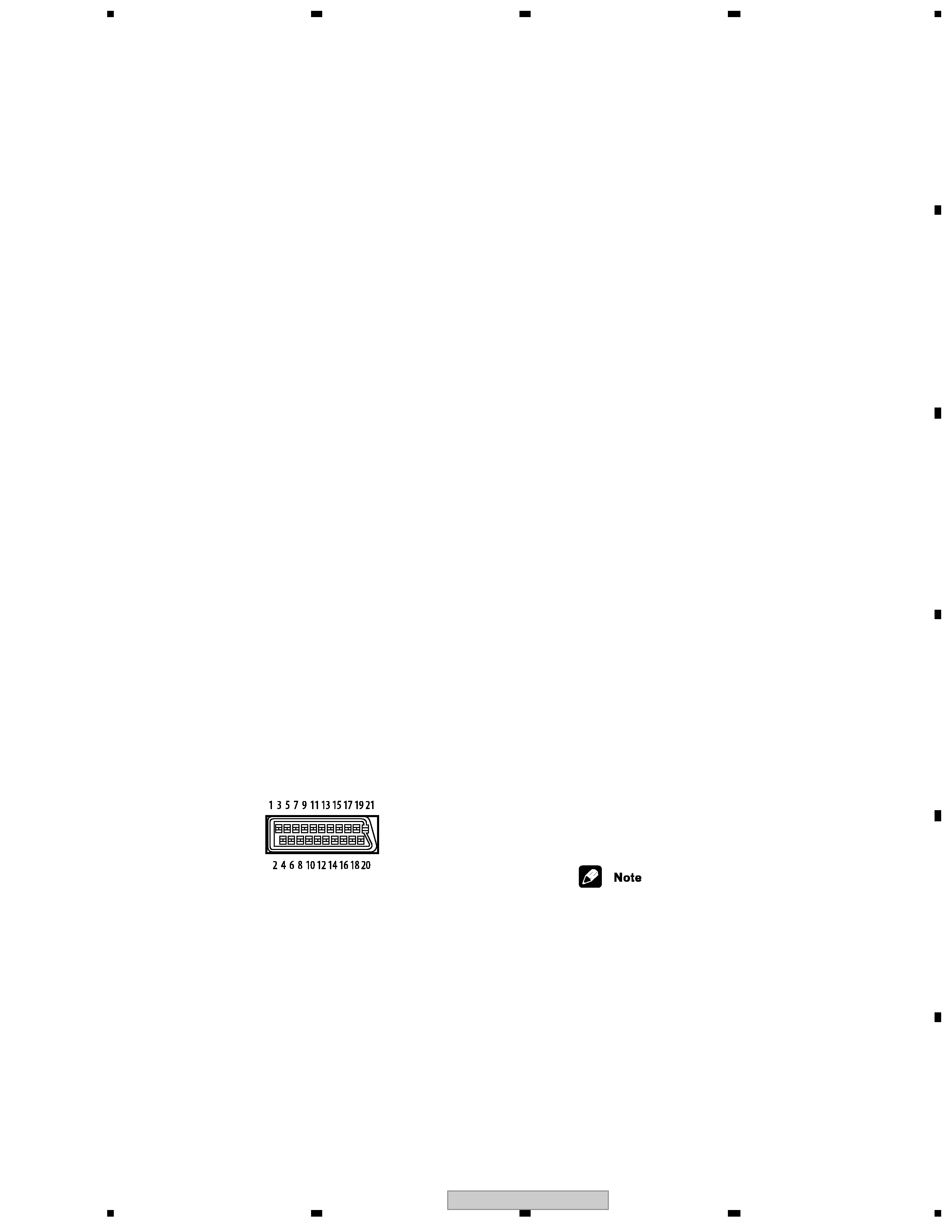
AV connector output
AV Connector
(21-pin connector assignment)
AV connector output. . . . . . . . .21-pin connector
This connector provides the video and audio
signals for connection to a compatible color TV
or monitor.
PIN no.
1 . . . . . . . . . . . . . . . . . . . . . . . . . . . Audio 2/R out
3 . . . . . . . . . . . . . . . . . . . . . . . . . . . .Audio 1/L out
4 . . . . . . . . . . . . . . . . . . . . . . . . . . . . . . . . . . .GND
7 . . . . . . . . . . . . . . . . . . . . . . . . . . . . . . . . . B* out
8 . . . . . . . . . . . . . . . . . . . . . . . . . . . . . . . . . Status
11 . . . . . . . . . . . . . . . . . . . . . . . . . . . . . . . . G* out
15 . . . . . . . . . . . . . . . . . . . . . . . . . . . R* or C* out
17. . . . . . . . . . . . . . . . . . . . . . . . . . . . . . . . . .GND
19 . . . . . . . . . . . . . . . . . . . . . .Video out or Y* out
21 . . . . . . . . . . . . . . . . . . . . . . . . . . . . . . . . . .GND
*AV CONNECTOR 1 (RGB)-TV/AV Receiver is
output
Audio output (1 stereo pair)
Output level . . . . . . . . . . . . .During audio output
200 mVrms (1 kHz, 20 dB)
Number of channels. . . . . . . . . . . . . . . . . . . . . .2
Jacks. . . . . . . . . . . . . . . . . . . . . . . . . . . RCA jack
Audio output (multi-channel / L, R, C,
SW, LS, RS)
Output level . . . . . . . . . . . . . During audio output
200 mVrms (1 kHz, 20 dB)
Number of channels. . . . . . . . . . . . . . . . . . . . . .6
Jacks . . . . . . . . . . . . . . . . . . . . . . . . . . . RCA jack
Audio characteristics
Frequency response
. . . . . . . . . . . . . .4 Hz to 44 kHz(DVD fs: 96 kHz)
. . . . . . . 4 Hz to 88 kHz (DVD-Audio fs: 192 kHz)
S/N ratio. . . . . . . . . . . . . . . . . . . . . . . . . . . .118dB
Dynamic range . . . . . . . . . . . . . . . . . . . . 108.8dB
Total harmonic distortion . . . . . . . . . . . 0.0008 %
Wow and flutter . . . . . . . . Limit of measurement
(0.001% W. PEAK) or lower
Digital output
Optical digital output . . . . . . Optical digital jack
Coaxial digital output . . . . . . . . . . . . . . RCA jack
Other terminals
Control in . . . . . . . . . . . . . . . . . . .Minijack (3.5ø)
Control out . . . . . . . . . . . . . . . . . .Minijack (3.5 ø)
Accessories
Stereo audio cable . . . . . . . . . . . . . . . . . . . . . . . .1
Video cable. . . . . . . . . . . . . . . . . . . . . . . . . . . . . .1
4-pin S400 i.LINK cable . . . . . . . . . . . . . . . . . . . .1
Power cable . . . . . . . . . . . . . . . . . . . . . . . . . . . . .1
Remote control . . . . . . . . . . . . . . . . . . . . . . . . . .1
AA/R6P dry cell batteries . . . . . . . . . . . . . . . . . . 2
Warranty card . . . . . . . . . . . . . . . . . . . . . . . . . . .1
These operating instructions
The specifications and design of this
product are subject to change without
notice, due to improvement.
. . . . . . . . . . . . . . . . . . . . . . . . 19 pin