ORDER NO.
PIONEER CORPORATION 4-1, Meguro 1-chome, Meguro-ku, Tokyo 153-8654, Japan
PIONEER ELECTRONICS (USA) INC. P.O. Box 1760, Long Beach, CA 90801-1760, U.S.A.
PIONEER EUROPE NV Haven 1087, Keetberglaan 1, 9120 Melsele, Belgium
PIONEER ELECTRONICS ASIACENTRE PTE. LTD. 253 Alexandra Road, #04-01, Singapore 159936
PIONEER CORPORATION 2005
STANDBY/ON
OPEN/CLOSE
TOP MENU
MENU
RETURN
HOME
MENU
DVD PLAYER
DV-686A-S
DV-686A-S
RRV3200
DVD PLAYER
DV-686A-S
DV-6800A-G
THIS MANUAL IS APPLICABLE TO THE FOLLOWING MODEL(S) AND TYPE(S).
Model
Type
Power Requirement
Region No.
The voltage can be converted
by the following method.
DV-686A-S
RDXTL/RA
AC110-127V/220-240V
1
Automatic select
DV-686A-S
RTXTL
AC110-127V/220-240V
3
Automatic select
DV-6800A-G
RAXTL
AC110-127V/220-240V
6
Automatic select
For details, refer to "
Important Check Points for Good Servicing" .
T-ZZR JUNE 2005 printed in Japan
DV-686A-S
2
12
34
12
3
4
C
D
F
A
B
E
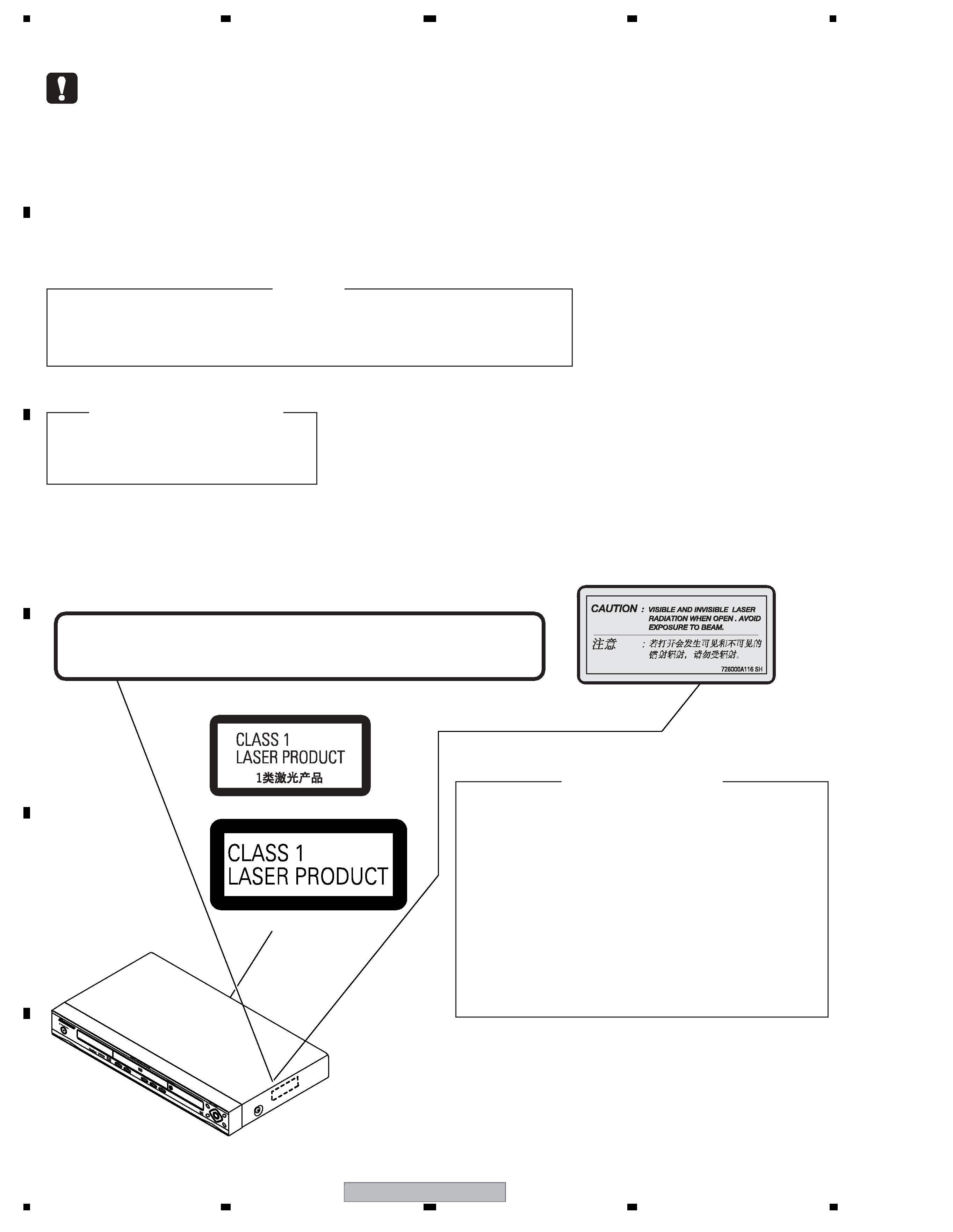
SAFETY INFORMATION
This service manual is intended for qualified service technicians ; it is not meant for the casual do-
it-yourselfer. Qualified technicians have the necessary test equipment and tools, and have been
trainedto properly and safely repair complex products such as those covered by this manual.
Improperly performed repairs can adversely affect the safety and reliability of the product and
may void the warranty. If you are not qualified to perform the repair of this product properly and
safely, you should not risk trying to do so and refer the repair to a qualified service technician.
WARNING !
THE AEL (ACCESSIBLE EMISSION LEVEL) OF THE LASER POWER OUTPUT IS LESS THAN CLASS 1
BUT THE LASER COMPONENT IS CAPABLE OF EMITTING RADIATION EXCEEDING THE LIMIT FOR
CLASS 1.
A SPECIALLY INSTRUCTED PERSON SHOULD DO SERVICING OPERATION OF THE APPARATUS.
LASER DIODE CHARACTERISTICS
FOR DVD : MAXIMUM OUTPUT POWER : 5 mW
WAVELENGTH : 650 nm
FOR CD :
MAXIMUM OUTPUT POWER : 5 mW
WAVELENGTH : 780 nm
Additional Laser Caution
: See page 51.
1.
· Laser diode is driving with Q2303,Q2305(650nm LD) and Q2302,
Q2304(780nm LD)on the DVD MT PCB Assy.
Therefore, when short-circuit between the emitter and collector of these
transistors or the base voltage is supplied for transistors turn on, the
laser oscillates. (failure mode)
· In the test mode
, there is the mode that the laser oscillates except
for the disc judgment and playback. LD ON mode in the test mode
oscillates with the laser forcibly.
2. When the cover is open, close viewing through the objective lens with
the naked eye will cause exposure to the laser beam.
LABEL CHECK
(Printed on the Rear Panel)
Location: inside of the unit
726000A116
VORSICHT : SICHTBARE UND UNSICHTBARE LASERSTRAHLUNG,WENNABDECKUNG GEÖFFNET NICHT DEM STRAHL AUSSETZEN !
CAUTION
: VISIBLE AND INVISIBLE LASER RADIATION WHEN OPEN. AVOID EXPOSURE TO BEAM.
ADVARSEL : SYNLIG OG USYNLIG LASERSTRÅLING VED ÅBNING UNDGÅ UDSÆTTELSE FOR STRÀLING.
VARO!
: AVATTAESSA ALTISTUT NÄKYVÄ JA NÄKYMÄTTÖMÄLLE LASERSATEIL YLLE. ÄLÄ KATSO SÄTEESEN.
VARNING
: SYNLIG OCH OSYNLIG LASERSTRÅLNING NÄR DENNA DEL ÄR ÖPPNAD BETRAKTA EJ STRÅLEN.
7260000356 SH
CUIDADO
: RADIACIÓN LÁSER VISIBLE E INVISIBLE AL ESTAR ABIERTO. EVITAR EXPOSICIÓN AL RAYO.
for /RDXTL and /RTXTL model
for /RDXTL and /RTXTL model
for /RAXTL model
for /RAXTL model
DV-686A-S
3
56
78
56
7
8
C
D
F
A
B
E
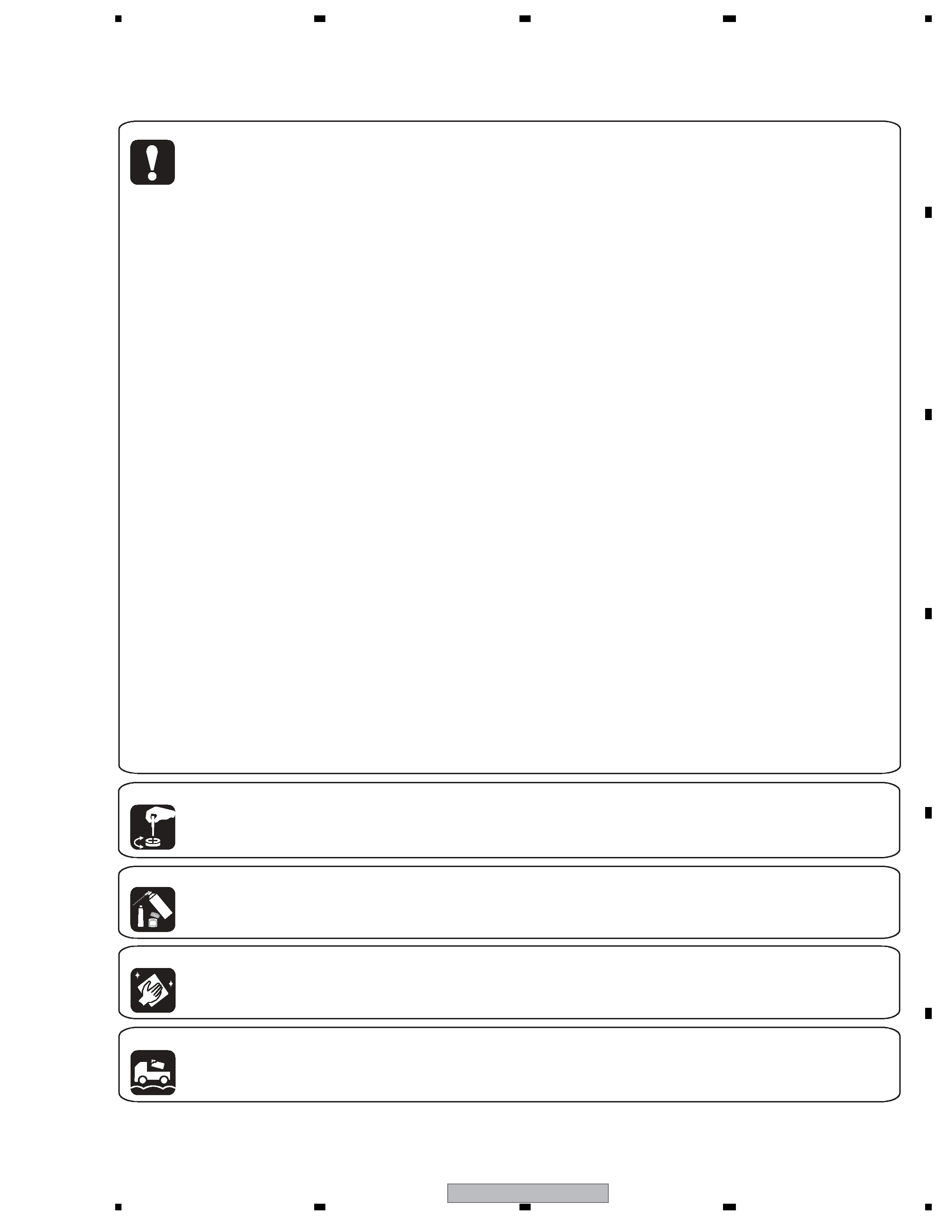
[Important Check Points for Good Servicing]
In this manual, procedures that must be performed during repairs are marked with the below symbol.
Please be sure to confirm and follow these procedures.
1. Product safety
Please conform to product regulations (such as safety and radiation regulations), and maintain a safe servicing environment by
following the safety instructions described in this manual.
1 Use specified parts for repair.
Use genuine parts. Be sure to use important parts for safety.
2 Do not perform modifications without proper instructions.
Please follow the specified safety methods when modification(addition/change of parts) is required due to interferences such as
radio/TV interference and foreign noise.
3 Make sure the soldering of repaired locations is properly performed.
When you solder while repairing, please be sure that there are no cold solder and other debris.
Soldering should be finished with the proper quantity. (Refer to the example)
4 Make sure the screws are tightly fastened.
Please be sure that all screws are fastened, and that there are no loose screws.
5 Make sure each connectors are correctly inserted.
Please be sure that all connectors are inserted, and that there are no imperfect insertion.
6 Make sure the wiring cables are set to their original state.
Please replace the wiring and cables to the original state after repairs.
In addition, be sure that there are no pinched wires, etc.
7 Make sure screws and soldering scraps do not remain inside the product.
Please check that neither solder debris nor screws remain inside the product.
8 There should be no semi-broken wires, scratches, melting, etc. on the coating of the power cord.
Damaged power cords may lead to fire accidents, so please be sure that there are no damages.
If you find a damaged power cord, please exchange it with a suitable one.
9 There should be no spark traces or similar marks on the power plug.
When spark traces or similar marks are found on the power supply plug, please check the connection and advise on secure
connections and suitable usage. Please exchange the power cord if necessary.
0 Safe environment should be secured during servicing.
When you perform repairs, please pay attention to static electricity, furniture, household articles, etc. in order to prevent injuries.
Please pay attention to your surroundings and repair safely.
2. Adjustments
To keep the original performance of the products, optimum adjustments and confirmation of characteristics within specification.
Adjustments should be performed in accordance with the procedures/instructions described in this manual.
4. Cleaning
For parts that require cleaning, such as optical pickups, tape deck heads, lenses and mirrors used in projection monitors, proper
cleaning should be performed to restore their performances.
3. Lubricants, Glues, and Replacement parts
Use grease and adhesives that are equal to the specified substance.
Make sure the proper amount is applied.
5. Shipping mode and Shipping screws
To protect products from damages or failures during transit, the shipping mode should be set or the shipping screws should be
installed before shipment. Please be sure to follow this method especially if it is specified in this manual.

DV-686A-S
4
12
34
12
3
4
C
D
F
A
B
E
CONTENTS
SAFETY INFORMATION ..................................................................................................................................... 2
1. SPECIFICATIONS ............................................................................................................................................ 5
2. EXPLODED VIEWS AND PARTS LIST ............................................................................................................ 6
2.1 PACKING SECTION .................................................................................................................................. 6
2.2 EXTERIOR SECTION............................................................................................................................... 8
2.3 05 DVD MECHA SECTION...................................................................................................................... 10
3. BLOCK DIAGRAM AND SCHEMATIC DIAGRAM ..........................................................................................12
3.1 BLOCK DIAGRAM ................................................................................................................................... 12
3.2 OVERALL WIRING CONNECTION DIAGRAM........................................................................................ 14
3.3 DVD MT PCB (1/6) ASSY ........................................................................................................................ 16
3.4 DVD MT PCB (2/6) ASSY ........................................................................................................................ 18
3.5 DVD MT PCB (3/6) ASSY ........................................................................................................................ 20
3.6 DVD MT PCB (4/6) ASSY ........................................................................................................................ 22
3.7 DVD MT PCB (5/6) ASSY ........................................................................................................................ 24
3.9 OPERATION, OPERATION 2 and OPERATION 3 PCB ASSYS ............................................................. 28
3.10 POWER PCB (1/2) ASSY ...................................................................................................................... 30
3.11 POWER PCB (2/2) ASSY ...................................................................................................................... 32
3.12 WAVEFORMS ........................................................................................................................................ 34
4. PCB CONNECTION DIAGRAM ..................................................................................................................... 37
4.1 LOADING and SW PCB ASSYS.............................................................................................................. 37
4.2 DVD MT PCB ASSY................................................................................................................................. 38
4.3 OPERATION, OPERATION 2 and OPERATION 3 PCB ASSYS ............................................................. 42
4.4 POWER PCB ASSY................................................................................................................................. 46
5. PCB PARTS LIST ........................................................................................................................................... 48
6. ADJUSTMENT ............................................................................................................................................... 50
6.1 WHEN REPLACING DVD DECK ............................................................................................................. 50
6.2 TEST MODE ............................................................................................................................................ 51
6.3 TEST MODE IN........................................................................................................................................ 52
6.4 DISC REMOVAL METHOD...................................................................................................................... 53
7. GENERAL INFORMATION ............................................................................................................................. 54
7.1 DIAGNOSIS ............................................................................................................................................. 54
7.1.1 DISPLAY SPECIFICATION OF THE TEST MODE ............................................................................ 54
7.1.2 FUNCTIONAL SPECIFICATION OF THE SHORTCUT KEY ............................................................ 55
7.1.3 SPECIFICATION OF MODEL INFORMATION DISPLAY .................................................................. 56
7.1.4 FUNCTIONAL SPECIFICATION OF THE SERVICE MODE ............................................................. 57
7.1.5 METHOD FOR DIAGNOSING DEGRADATION OF THE LDS ON THE PICKUP ASSY .................. 58
7.1.6 TROUBLE SHOOTING ...................................................................................................................... 59
7.2 DISASSEMBLY ........................................................................................................................................ 61
7.3 DVD DECK SECTION.............................................................................................................................. 62
7.4 IC INFORMATION.................................................................................................................................... 66
8. PANEL FACILITIES ........................................................................................................................................ 78
8.1 FRONT PANEL SECTION ....................................................................................................................... 78
8.2 DISPLAY .................................................................................................................................................. 79
8.3 REMOTE CONTROL ............................................................................................................................... 80

DV-686A-S
5
56
78
56
7
8
C
D
F
A
B
E
1. SPECIFICATIONS
Specifications
General
System
. . . . . . . . . . . . . . . . . . . . . . DVD player
Power consumption . . . . . . . . . . . . . . . . . 8 W
Power consumption (standby) . . . . . .
0.85 W
Weight . . . . . . . . . . . . . . . . . . . . . . . .
1.7kg
Dimensions:
. . .
420 (W) x 49.5 (H) x 225.5 (D) mm
Operating temperature . . . . . . . +5
°C to +35°C
Operating humidity . . . . . . . . . . . . . 5% to 85%
(no condensation)
Component video output
Y (luminance) - Output level . . . 1 Vp-p (75
)
PB (color) - Output level
PR (color) - Output level . . . . . 0.7 Vp-p (75 )
Jack
Digital audio characteristics
Frequency response . . . . . . . . 4 Hz to 44 kHz
(DVD fs: 96 kHz)
S/N ratio . . . . . . . . . . . . . . . . . . . . . . . . . 115 dB
Dynamic range . . . . . . . . . . . . . . . . . . . . 101 dB
Total harmonic distortion . . . . . . . . . .
0.0023 %
Wow and flutter . . . . . . Limit of measurement
(
±0.001% W. PEAK) or lower
Digital output
Coaxial digital output . . . . . . . . . . . . . RCA jack
Accessories
Audio/video cable. . . . . . . . . . . . . . . . . . . . . . . . 1
Remote control . . . . . . . . . . . . . . . . . . . . . . . . . . 1
AA/R6P dry cell batteries . . . . . . . . . . . . . . . . . . . 2
Operating Instructions
The specifications and design of this product are subject to
change without notice, due to improvement.
Published by Pioneer Corporation.
Copyright © 2005 Pioneer Corporation.
All rights reserved
. . . . 0.7 Vp-p (75
)
. . . . . . . . . . . . . . . . . . . . . . . . . . . . . . RCA
S-video output
Y (luminance) - Output level . . . . . 1 Vp-p (75
)
C (color) - Output level . . . . . . 286 mVp-p (75
)
Jack . . . . . . . . . . . . . . . . . . . . . . . . . . . . S-video
Video output
Output level. . . . . . . . . . . . . . . . . . 1 Vp-p (75
)
Jack. . . . . . . . . . . . . . . . . . . . . . . . . . . . . . . RCA
Audio output (1 stereo pair)
Output level . . . . . . . . . . . . During audio output
200 mVrms (1 kHz, 20 dB)
Number of channels . . . . . . . . . . . . . . . . . . . . . 2
Jacks . . . . . . . . . . . . . . . . . . . . . . . . . . . . RCA
(+41
°F to +95°F)
Audio output (multi-channel / L, R, C, SW,
SL, SR)
Output level . . . . . . . . . . . . . During audio output
200 mVrms (1 kHz, 20 dB)
Number of channels . . . . . . . . . . . . . . . . . . . . . 6
Jacks . . . . . . . . . . . . . . . . . . . . . . . . . . . . RCA jack
4 Hz to 88 kHz (DVD-Audio fs: 192 kHz)
Optical digital output . . . . . . . Optical digital jack
Power requirements
Other models . . AC 110127/220240 V, 50/60 Hz
Power cable
Others . . . . . . . . . . . . . . . . . . . . . . . . . . . . . . . . . 1