ORDER NO.
PIONEER CORPORATION 4-1, Meguro 1-chome, Meguro-ku, Tokyo 153-8654, Japan
PIONEER ELECTRONICS SERVICE, INC. P.O. Box 1760, Long Beach, CA 90801-1760, U.S.A.
PIONEER EUROPE NV Haven 1087, Keetberglaan 1, 9120 Melsele, Belgium
PIONEER ELECTRONICS ASIACENTRE PTE. LTD. 253 Alexandra Road, #04-01, Singapore 159936
PIONEER CORPORATION 2001
c
DV-545
RRV2465
T IZE JUNE 2001 Printed in Japan
DV-444-S
THIS MANUAL IS APPLICABLE TO THE FOLLOWING MODEL(S) AND TYPE(S).
DVD PLAYER
1. SAFETY INFORMATION ....................................... 2
2. EXPLODED VIEWS AND PARTS LIST ................. 3
3. BLOCK DIAGRAM AND SCHEMATIC DIAGRAM ... 10
4. PCB CONNECTION DIAGRAM ........................... 35
5. PCB PARTS LIST ................................................ 46
6. ADJUSTMENT ..................................................... 51
CONTENTS
7. GENERAL INFORMATION ................................ 57
7.1 DIAGNOSIS .................................................. 57
7.1.1 SELF-DIAGNOSTIC FUNCTION OF
PICKUP DEFECTIVE ........................... 57
7.1.2 TEST POINTS LOCATION ................... 58
7.1.3 TEST MODE SCREEN DISPLAY ........ 59
7.1.4 TROUBLE SHOOTING ........................ 63
7.1.5 ERROR CODE ..................................... 64
7.1.6 DISASSEMBLY .................................... 68
7.2 PARTS .......................................................... 74
7.2.1 IC .......................................................... 74
7.2.2 FL DISPLAY ......................................... 93
8. PANEL FACILITIES AND SPECIFICATIONS .... 94
DV-444-K
Type
Model
Power Requirement
Region No.
Remarks
DV-545
DV-444-S
DV-444-K
WYXJ
?
--
AC220-240V
2
WVXJ
?
--
AC220-240V
2
WYXQ
-
??
AC220-240V
2
WYXQ/FRGR
-
??
AC220-240V
2
WVXQ
-
??
AC220-240V
2
Î
8
7
¡¢
41
STANDBY/ON
0
3
DVDPLAYER
LEGATO
PRO
DV-545
2
DV-545, DV-444-S, DV-444-K
This service manual is intended for qualified service technicians ; it is not meant for the casual do-it-
yourselfer. Qualified technicians have the necessary test equipment and tools, and have been trained
to properly and safely repair complex products such as those covered by this manual.
Improperly performed repairs can adversely affect the safety and reliability of the product and may
void the warranty. If you are not qualified to perform the repair of this product properly and safely, you
should not risk trying to do so and refer the repair to a qualified service technician.
WARNING !
THE AEL (ACCESSIBLE EMISSION LEVEL) OF THE LASER POWER OUTPUT IS LESS THAN CLASS 1
BUT THE LASER COMPONENT IS CAPABLE OF EMITTING RADIATION EXCEEDING THE LIMIT FOR
CLASS 1.
A SPECIALLY INSTRUCTED PERSON SHOULD DO SERVICING OPERATION OF THE APPARATUS.
LASER DIODE CHARACTERISTICS
FOR DVD : MAXIMUM OUTPUT POWER : 5 mW
WAVELENGTH : 650 nm
FOR CD :
MAXIMUM OUTPUT POWER : 5 mW
WAVELENGTH : 780 nm
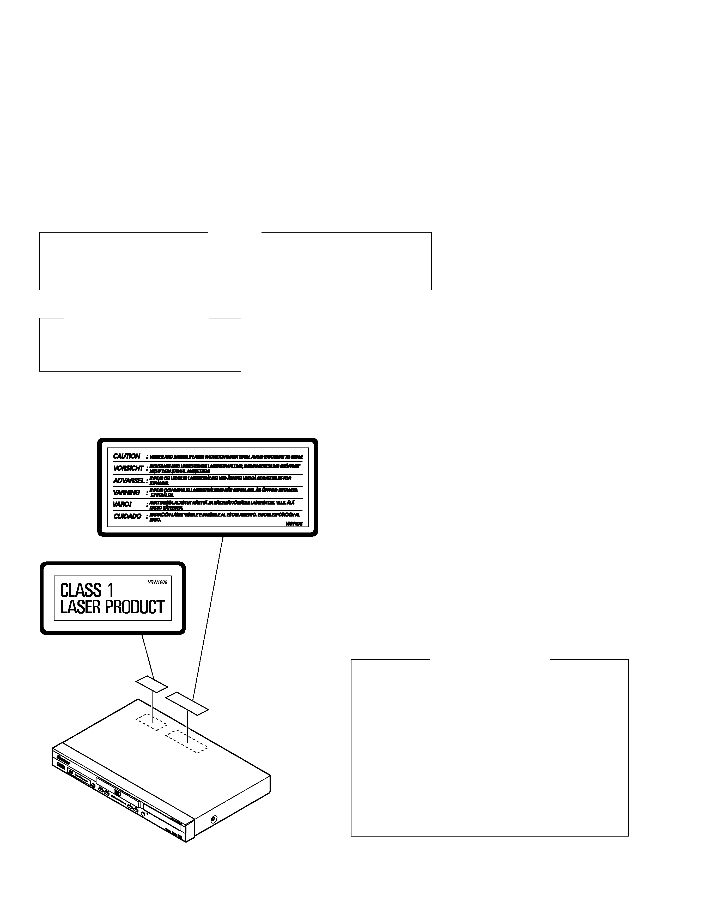
LABEL CHECK
DV-545/WYXJ
Only
1. SAFETY INFORMATION
Additional Laser Caution
1. Loading-status detection switch (S101 on the LOAB assy) are detected
by the microprocessor (IC601 in the DVDM assy).
· To permit the laser diode to oscillate, it is required to set the loading-
status detection switch for the clamp position (the center terminal of S101
is shorted to +3V).
When the voltage of IC101-pin 20 is +3V and IC601 (microprocessor) -
pin 83 is +3V, 650nm laser diode for DVD oscillates in the DVDM Assy.
When the voltage of IC101-pin 20 is +3V and IC601 (microprocessor) -
pin 83 is 0V (GND), 780nm laser diode for CD oscillates in the DVDM
Assy.
In the test mode
, the laser diode oscillates when microprocessor detects
a PLAY signal, or when the PLAY key is pressed (S203 ON in the FLKB
assy), with the above requirements satisfied.
2. When the cover is open, close viewing through the objective lens with
the naked eye will cause exposure to the laser beam.
: See page 53.
DV-545, DV-444-S, DV-444-K
3
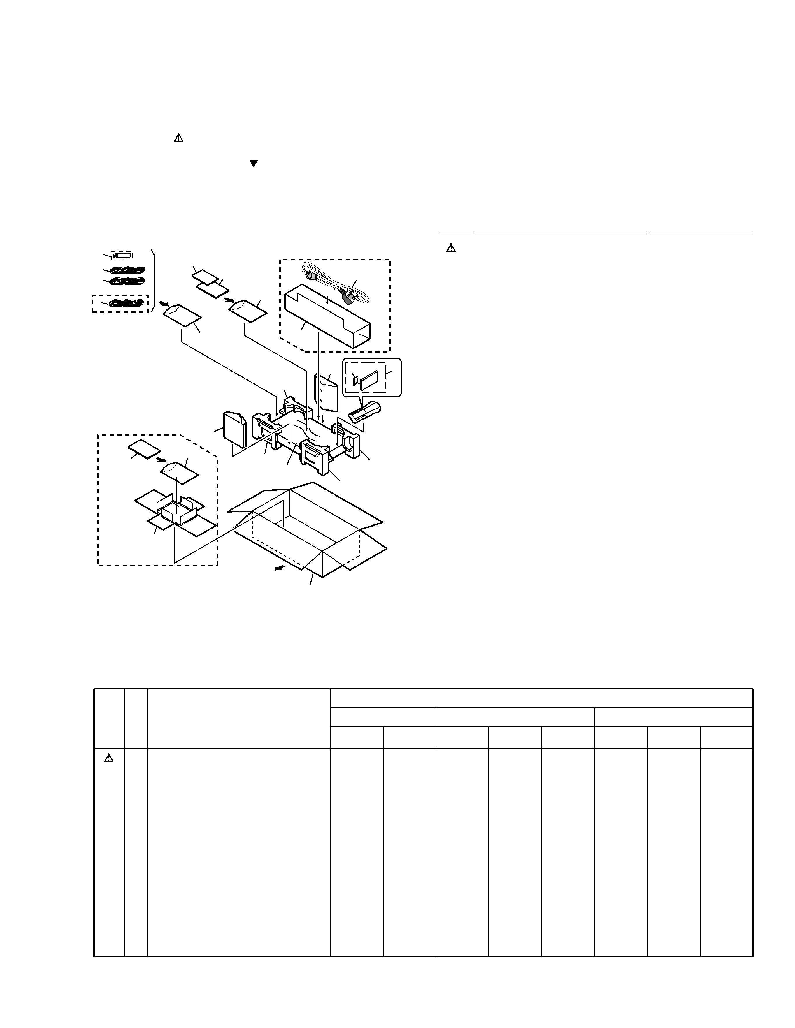
2.1 PACKING
1
Power Cord
See Contrast table (2)
2
Audio Cord (L = 1.5m)
See Contrast table (2)
3
Video Cord (L = 1.5m)
See Contrast table (2)
4
Remote Control Unit
See Contrast table (2)
5
Battery Cover
See Contrast table (2)
NSP
6
Dry Cell Battery (R6P, AA)
See Contrast table (2)
7
Pad
VHA1277
NSP
8
Warranty Card
ARY7022
9
Packing Case
See Contrast table (2)
10
Mirror Mat (0.5
× 750 × 600)
Z23-007
NSP
11
Reinforcement Board
VHC1083
12
Polyethylene Bag
VHL1051
(0.03
× 200 × 300)
NSP
13
Polyethylene Bag
Z21-038
(0.03
× 230 × 340)
14
IM Holder
See Contrast table (2)
15
Accessory Box
See Contrast table (2)
16
Operating Instructions
See Contrast table (2)
17
Operating Instructions
See Contrast table (2)
18
Operating Instructions
See Contrast table (2)
19
Operating Instructions
See Contrast table (2)
(1) PACKING PARTS LIST
Mark No.
Description
Part No.
2. EXPLODED VIEWS AND PARTS LIST
NOTES:
· Parts marked by "NSP" are generally unavailable because they are not in our Master Spare Parts List.
· The mark found on some component parts indicates the importance of the safety factor of the part.
Therefore, when replacing, be sure to use parts of identical designation.
· Screws adjacent to mark on the product are used for disassembly.
(2) CONTRAST TABLE
DV-545/WYXJ, WVXJ, DV-444-S/WYXQ, WYXQ/FRGR, WVXQ, DV-444-K/WYXQ, WYXQ/FRGR and WVXQ are constructed
the same except for the following :
Mark No.
Symbol and Description
Part No.
DV-545
DV-444-S
DV-444-K
WYXJ
WVXJ
WYXQ
WYXQ
/FRGR
WVXQ
WYXQ
WYXQ
/FRGR
WVXQ
NSP
1
2
3
4
5
6
9
14
15
16
17
18
19
Power Cord
Audio Cord (L = 1.5m)
Video Cord (L = 1.5m)
Remote Control Unit
Battery Cover
Dry Cell Battery (R6P, AA)
Packing Case
IM Holder
Accessory Box
Operating Instructions (English/Italian)
Operating Instructions (French/German)
Operating Instructions (Dutch/Swedish)
Operating Instructions
(Spanish/Portuguese)
ADG1154
VDE1052
VDE1053
VXX2627
VNK4423
VEM-013
VHG2121
VHC1082
Not used
VRD1132
VRD1133
VRD1134
VRD1135
ADG1156
VDE1052
VDE1053
VXX2627
VNK4423
VEM-013
VHG2096
Not used
VHC1080
VRD1132
Not used
Not used
Not used
ADG1154
VDE1054
VDE1055
VXX2702
VNK4631
VEM1010
VHG2083
VHC1082
Not used
VRD1137
VRD1138
VRD1139
VRD1140
ADG1154
VDE1054
VDE1055
VXX2702
VNK4631
VEM1010
VHG2102
Not used
Not used
Not used
VRD1138
Not used
Not used
ADG1156
VDE1054
VDE1055
VXX2702
VNK4631
VEM1010
VHG2103
Not used
VHC1080
VRD1137
Not used
Not used
Not used
ADG1154
VDE1054
VDE1055
VXX2702
VNK4631
VEM1010
VHG2080
VHC1082
Not used
VRD1137
VRD1138
VRD1139
VRD1140
ADG1154
VDE1054
VDE1055
VXX2702
VNK4631
VEM1010
VHG2100
Not used
Not used
Not used
VRD1138
Not used
Not used
ADG1156
VDE1054
VDE1055
VXX2702
VNK4631
VEM1010
VHG2101
Not used
VHC1080
VRD1137
Not used
Not used
Not used
FRONT
16, 17
"Operating
Instructions"
18, 19
"Operating
Instructions"
13
15
1
12
8
11
12
11
10
9
5
4
6
3
2
1
7 (1/2)
7 (2/2)
7 (1/2)
7 (2/2)
14
WYXJ and WYXQ
Types Only
Except
WVXJ and WVXQ
Types
WVXJ and WVXQ
Types Only
DV-545, DV-444-S, DV-444-K
4
A
A
B
D
E
F
B
C
C
D
F
E
20
23
21
21
24
24
26
25
30
30
30
30
31
30
30
30
30
30
30
22
5
9
6
30
30
27
27
14
15
27
27
27
7
16
19
28
28
2
Refer to
"2.3 LOADING MECHANISM ASSY".
28
29
12
11
11
13
4
10
1
17
8
3
28
28
28 28
28
29
18
32
33 DV-545 Only
B
D
H
C
F
G
E
DV-545
Only
DV-545
Only
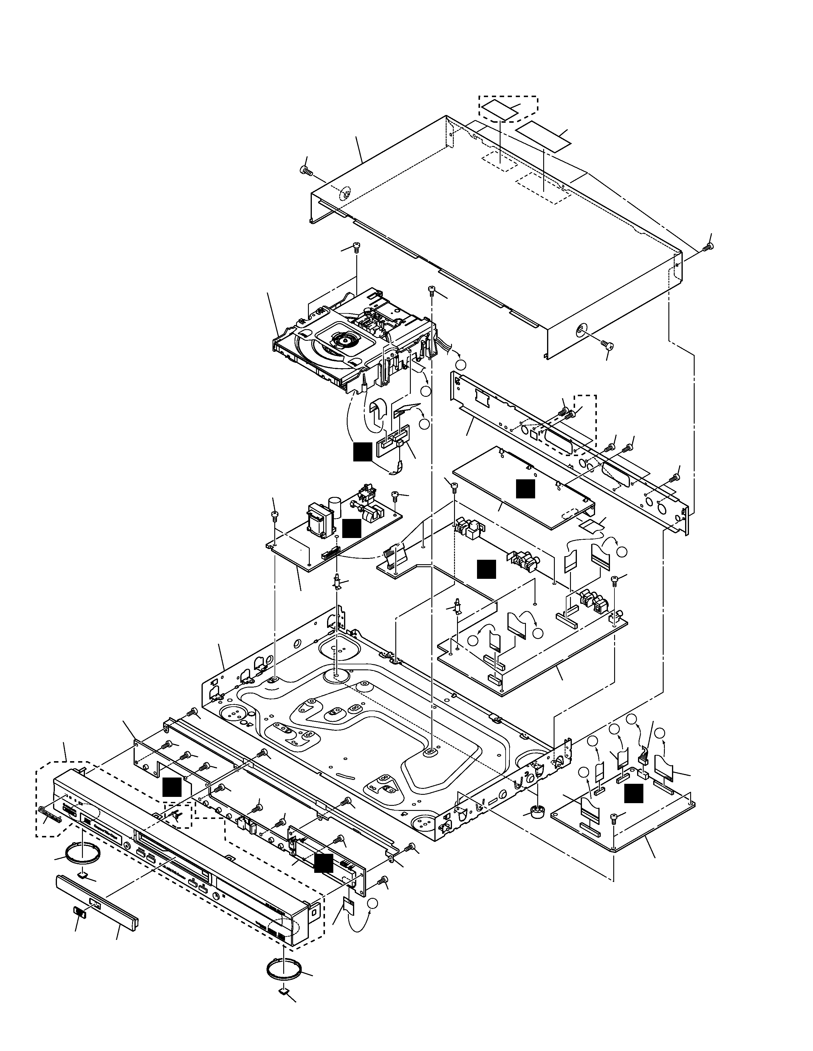
2.2 EXTERIOR SECTION
DV-545, DV-444-S, DV-444-K
5
1
DVDM Assy
See Contrast table (2)
NSP
2
Loading Mechanism Assy
VWT1188
NSP
3
SSIB Assy
VWG2292
4
JACB Assy
See Contrast table (2)
NSP
5
FLKB Assy
See Contrast table (2)
NSP
6
KEYB Assy
See Contrast table (2)
7
SRCB Assy
See Contrast table (2)
8
POWER SUPPLY Unit
VWR1340
9
Flexible Cable (16P)
See Contrast table (2)
10
Flexible Cable (17P)
See Contrast table (2)
11
Flexible Cable (30P)
See Contrast table (2)
12
Leg Assy SX
AEC7113
13
Connector Assy
PG05KK-E30
NSP
14
PCB Support
REC1285
15
PCB Support
VEC2184
16
Rear Panel
See Contrast table (2)
NSP
17
Base Chassis
VNA2300
18
Bonnet
See Contrast table (2)
19
Flexible Cable (19P)
See Contrast table (2)
20
DVD-V Plate
See Contrast table (2)
(1) EXTERIOR SECTION PARTS LIST
Mark No.
Description
Part No.
Mark No.
Symbol and Description
Part No.
Remarks
DV-545
DV-444-S
DV-444-K
WYXJ,
WVXJ
WYXQ,
WYXQ/FRGR,
WVXQ
WYXQ,
WYXQ/FRGR,
WVXQ
NSP
NSP
NSP
1
4
5
6
7
9
10
11
16
18
18
19
20
23
25
26
29
31
33
DVDM Assy
JACB Assy
FLKB Assy
KEYB Assy
SRCB Assy
Flexible Cable (16P)
Flexible Cable (17P)
Flexible Cable (30P)
Rear Panel
Bonnet S
Bonnet
Flexible Cable (19P)
DVD-V Plate
Tray Panel
Front Panel Assy
Pioneer Name Plate
Screw
LED Lens
CLASS 1 Caution Label
VWS1488
VWV1843
VWG2283
VWG2291
VWV1848
VDA1860
VDA1862
VDA1871
VNA2294
VXX2773
Not used
VDA1866
VAM1120
VNK4837
VXA2477
VAM1129
BCZ40P060FNI
VNK4841
VRW1889
VWS1487
VWV1842
VWG2282
VWG2290
VWV1847
VDA1861
VDA1863
VDA1872
VNA2344
Not used
VNA2333
VDA1867
VAM1121
VNK4837
VXA2469
VAM1129
BCZ40P060FNI
Not used
Not used
VWS1487
VWV1842
VWG2282
VWG2290
VWV1847
VDA1861
VDA1863
VDA1872
VNA2342
Not used
VNA2331
VDA1867
VAM1121
VNK4835
VXA2466
VAM1109
BCZ40P060FZK
Not used
Not used
(2) CONTRAST TABLE
DV-545/WYXJ, WVXJ, DV-444-S/WYXQ, WYXQ/FRGR, WVXQ, DV-444-K/WYXQ, WYXQ/FRGR and WVXQ are constructed
the same except for the following :
Mark No.
Description
Part No.
21
Rubber Foot
VEB1325
22
FP Angle
VNE2250
23
Tray Panel
See Contrast table (2)
24
Ring
VNK4840
25
Front Panel Assy
See Contrast table (2)
26
Pioneer Name Plate
See Contrast table (2)
27
Screw
BBZ30P060FMC
28
Screw
BBZ30P080FZK
29
Screw
See Contrast table (2)
30
Screw
BBZ30P100FZK
31
LED Lens
See Contrast table (2)
32
Label
VRW1872
33
CLASS 1 Caution Label
See Contrast table (2)